1993 CHEVROLET PLYMOUTH ACCLAIM wiring diagram
[x] Cancel search: wiring diagramPage 669 of 2438
CONCEALED HEADLAMPS INDEX
page page
Concealed Headlamp MotorÐAC-Body ........ 29
Diagnostic Procedures ..................... 27
General Information ....................... 27 Headlamp DoorÐAC-Body
................. 29
Headlamp DoorÐAY Body ................. 29
Headlamp Drive MotorÐAY Body ............ 30
GENERAL INFORMATION
For proper operation of the Concealed Headlamp
System, refer to the Owner's Manual provided with
the vehicle.
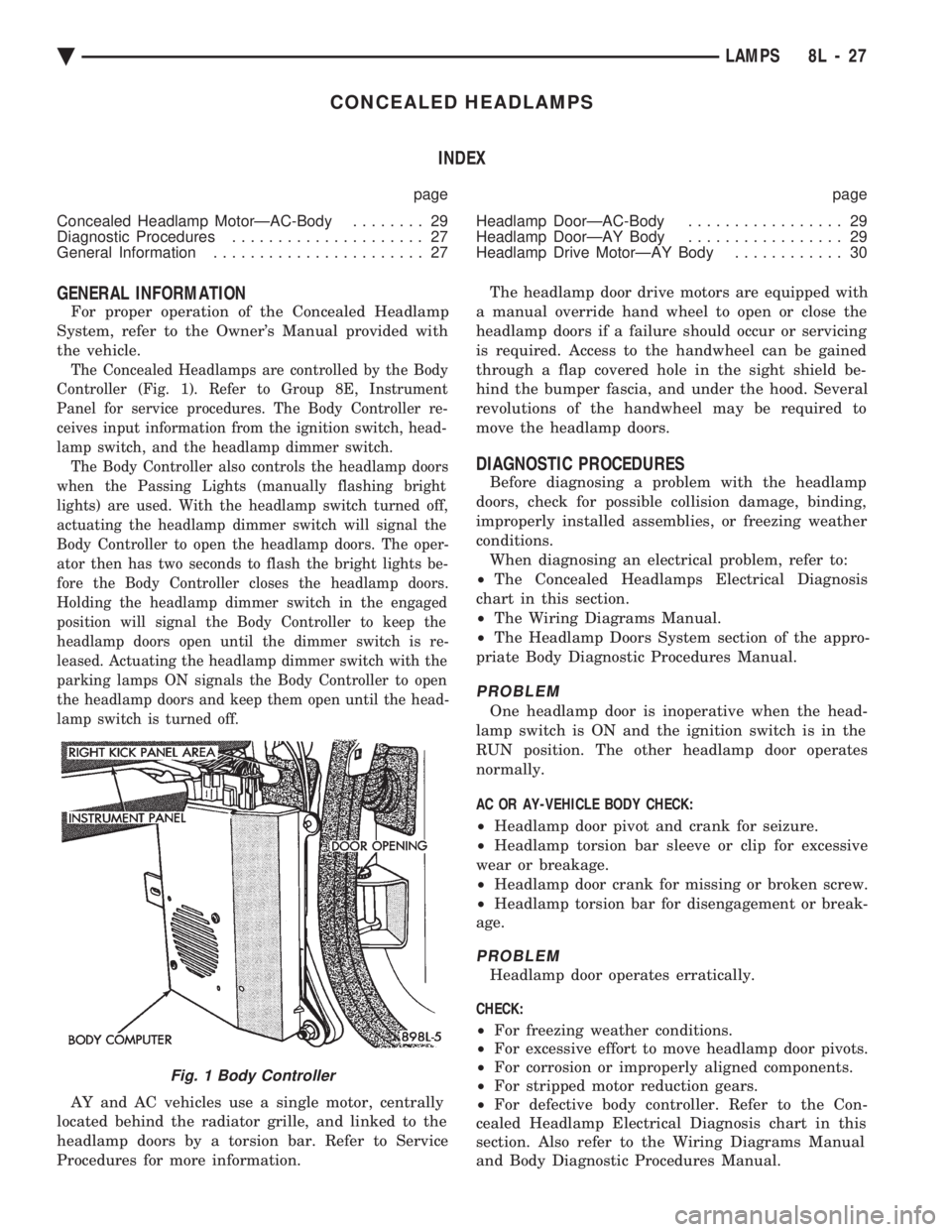
The Concealed Headlamps are controlled by the Body
Controller (Fig. 1). Refer to Group 8E, Instrument
Panel for service procedures. The Body Controller re-
ceives input information from the ignition switch, head-
lamp switch, and the headlamp dimmer switch. The Body Controller also controls the headlamp doors
when the Passing Lights (manually flashing bright
lights) are used. With the headlamp switch turned off,
actuating the headlamp dimmer switch will signal the
Body Controller to open the headlamp doors. The oper-
ator then has two seconds to flash the bright lights be-
fore the Body Controller closes the headlamp doors.
Holding the headlamp dimmer switch in the engaged
position will signal the Body Controller to keep the
headlamp doors open until the dimmer switch is re-
leased. Actuating the headlamp dimmer switch with the
parking lamps ON signals the Body Controller to open
the headlamp doors and keep them open until the head-
lamp switch is turned off.
AY and AC vehicles use a single motor, centrally
located behind the radiator grille, and linked to the
headlamp doors by a torsion bar. Refer to Service
Procedures for more information. The headlamp door drive motors are equipped with
a manual override hand wheel to open or close the
headlamp doors if a failure should occur or servicing
is required. Access to the handwheel can be gained
through a flap covered hole in the sight shield be-
hind the bumper fascia, and under the hood. Several
revolutions of the handwheel may be required to
move the headlamp doors.
DIAGNOSTIC PROCEDURES
Before diagnosing a problem with the headlamp
doors, check for possible collision damage, binding,
improperly installed assemblies, or freezing weather
conditions. When diagnosing an electrical problem, refer to:
² The Concealed Headlamps Electrical Diagnosis
chart in this section.
² The Wiring Diagrams Manual.
² The Headlamp Doors System section of the appro-
priate Body Diagnostic Procedures Manual.
PROBLEM
One headlamp door is inoperative when the head-
lamp switch is ON and the ignition switch is in the
RUN position. The other headlamp door operates
normally.
AC OR AY-VEHICLE BODY CHECK:
² Headlamp door pivot and crank for seizure.
² Headlamp torsion bar sleeve or clip for excessive
wear or breakage.
² Headlamp door crank for missing or broken screw.
² Headlamp torsion bar for disengagement or break-
age.
PROBLEM
Headlamp door operates erratically.
CHECK:
² For freezing weather conditions.
² For excessive effort to move headlamp door pivots.
² For corrosion or improperly aligned components.
² For stripped motor reduction gears.
² For defective body controller. Refer to the Con-
cealed Headlamp Electrical Diagnosis chart in this
section. Also refer to the Wiring Diagrams Manual
and Body Diagnostic Procedures Manual.
Fig. 1 Body Controller
Ä LAMPS 8L - 27
Page 675 of 2438
ILLUMINATED ENTRY SYSTEM INDEX
page page
Body Controller ComputerÐAC, AG, AJ and AY-Body ............................. 34
Diagnostic ProceduresÐAA-Body ............ 33 Diagnostic ProceduresÐAC, AG, AJ and AY-Body . 33
General Information ....................... 33
Illuminated Entry ModuleÐAA-Body ........... 34
GENERAL INFORMATION
AA-BODY
The Illuminated Entry System (on AA Body) actu-
ates the interior courtesy and/or dome lamps (except
for the illuminated ignition switch) by lifting either
front door exterior handle. Lamp illumination is terminated 35 seconds ( 68
seconds later when battery voltage is normal), or by
turning the ignition switch to the run position,
whichever occurs first. When testing the system, all
vehicle doors must be closed to prevent the door jam
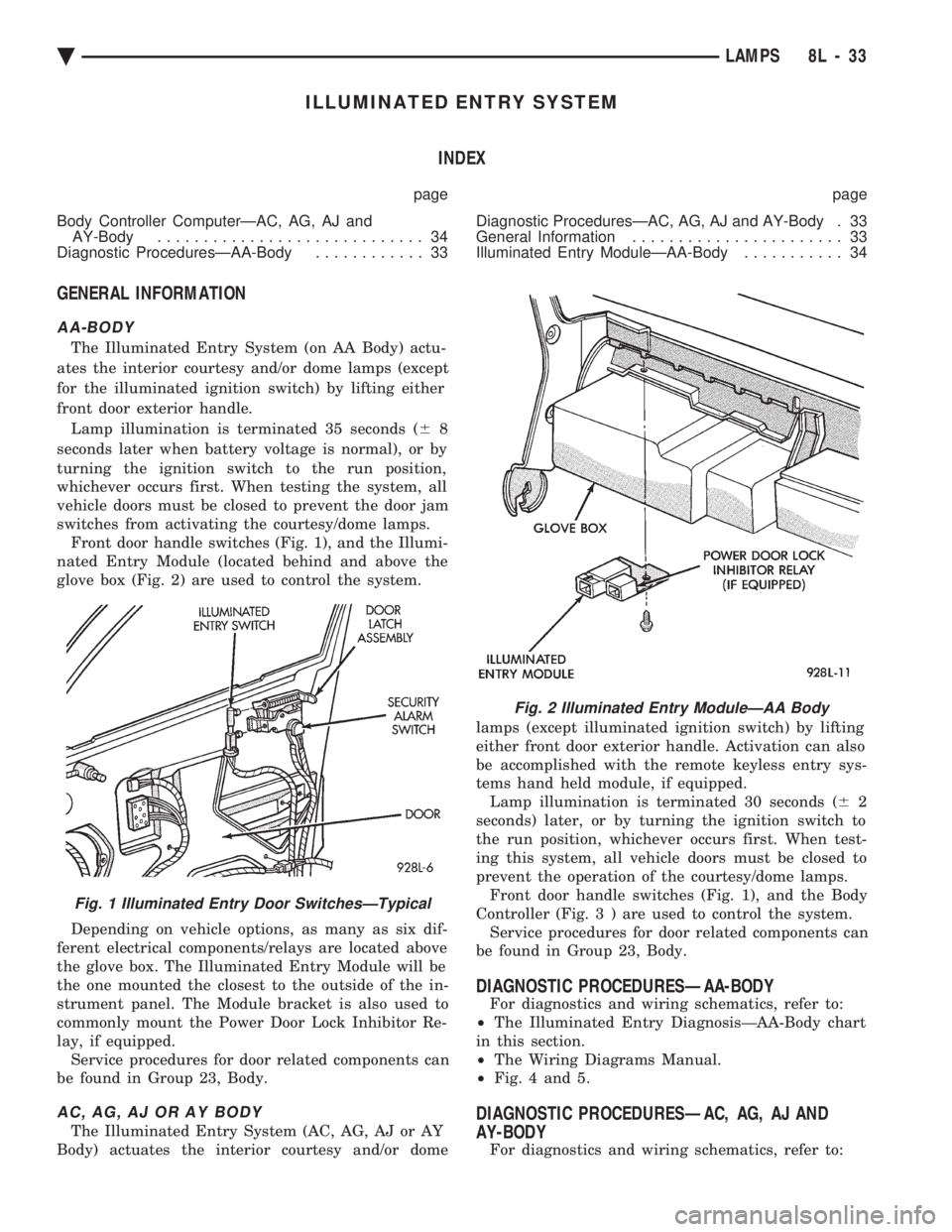
switches from activating the courtesy/dome lamps. Front door handle switches (Fig. 1), and the Illumi-
nated Entry Module (located behind and above the
glove box (Fig. 2) are used to control the system.
Depending on vehicle options, as many as six dif-
ferent electrical components/relays are located above
the glove box. The Illuminated Entry Module will be
the one mounted the closest to the outside of the in-
strument panel. The Module bracket is also used to
commonly mount the Power Door Lock Inhibitor Re-
lay, if equipped. Service procedures for door related components can
be found in Group 23, Body.
AC, AG, AJ OR AY BODY
The Illuminated Entry System (AC, AG, AJ or AY
Body) actuates the interior courtesy and/or dome lamps (except illuminated ignition switch) by lifting
either front door exterior handle. Activation can also
be accomplished with the remote keyless entry sys-
tems hand held module, if equipped. Lamp illumination is terminated 30 seconds ( 62
seconds) later, or by turning the ignition switch to
the run position, whichever occurs first. When test-
ing this system, all vehicle doors must be closed to
prevent the operation of the courtesy/dome lamps. Front door handle switches (Fig. 1), and the Body
Controller (Fig . 3 ) are used to control the system.
Service procedures for door related components can
be found in Group 23, Body.
DIAGNOSTIC PROCEDURESÐAA-BODY
For diagnostics and wiring schematics, refer to:
² The Illuminated Entry DiagnosisÐAA-Body chart
in this section.
² The Wiring Diagrams Manual.
² Fig. 4 and 5.
DIAGNOSTIC PROCEDURESÐAC, AG, AJ AND
AY-BODY
For diagnostics and wiring schematics, refer to:
Fig. 1 Illuminated Entry Door SwitchesÐTypical
Fig. 2 Illuminated Entry ModuleÐAA Body
Ä LAMPS 8L - 33
Page 676 of 2438
² The Illuminated Entry DiagnosisÐAC, AG, AJ
and AY-BODY chart in this section.
² The Illuminated Entry System section of the ap-
propriate Body Diagnostic Procedures Manual.
² The Wiring Diagrams Manual.
ILLUMINATED ENTRY MODULEÐAA-BODY
REMOVAL
(1) Disconnect the battery negative cable.
(2) Remove the glove box to gain access to the
module (Fig. 2). Refer to Group 8E, Instrument Panel
and Gauges. (3) Working through the glove box opening, discon-
nect the wiring connector at the module. (4) Remove the module bracket mounting screw.
(5) Remove the module bracket from the vehicle.
INSTALLATION
Reverse the preceding operation.
BODY CONTROLLER COMPUTERÐAC, AG, AJ and
AY-BODY
REMOVAL
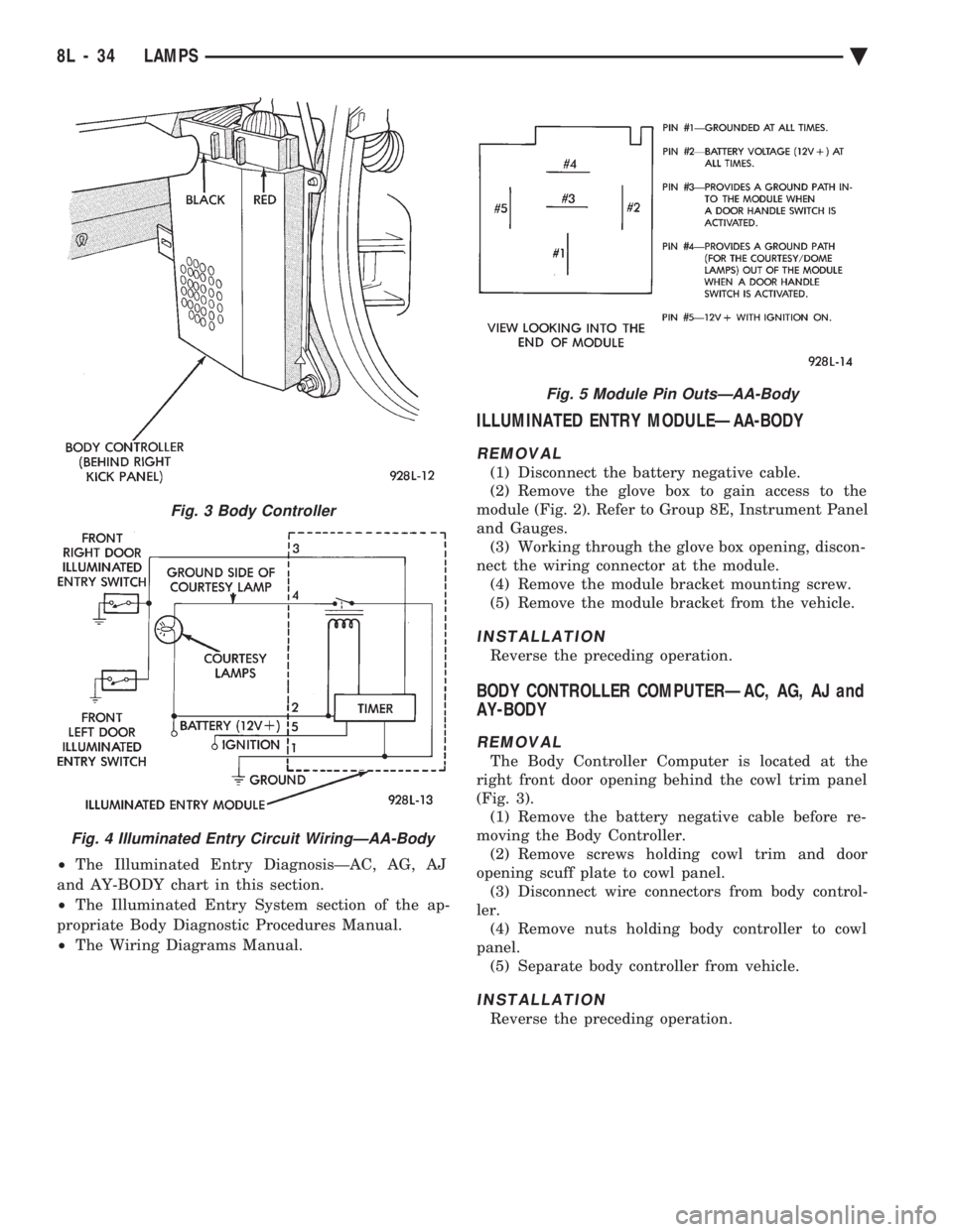
The Body Controller Computer is located at the
right front door opening behind the cowl trim panel
(Fig. 3). (1) Remove the battery negative cable before re-
moving the Body Controller. (2) Remove screws holding cowl trim and door
opening scuff plate to cowl panel. (3) Disconnect wire connectors from body control-
ler. (4) Remove nuts holding body controller to cowl
panel. (5) Separate body controller from vehicle.
INSTALLATION
Reverse the preceding operation.
Fig. 3 Body Controller
Fig. 4 Illuminated Entry Circuit WiringÐAA-Body
Fig. 5 Module Pin OutsÐAA-Body
8L - 34 LAMPS Ä
Page 692 of 2438

(6) Steps (3, 4 or 5) above will confirm system op-
eration. Indicator light illumination means that
there is power available at the output of the relay
only, and does not necessarily verify system opera-
tion. (7) If turning the switch ON produced no distinct
current draw on the ammeter the problem should be
isolated in the following manner: (a) Confirm the ignition switch is ON.
(b) Ensure that the heated rear glass feed wire is
connected to the terminal or pigtail and that the
ground wire is in fact grounded. (c) Ensure that the fusible link and control cir-
cuit fuse is operational and all electrical connec-
tions are secure.
(8) When the above steps have been completed and
the system is still inoperative, one or more of the fol-
lowing is defective: (a) Control switch/timer relay module.
(b) All rear window grid lines would have to be
broken or one of the feed wires are not connected
for the system to be inoperative.
(9) If turning the switch ON produces severe volt-
meter deflection, the circuit should be closely
checked for a shorting condition. (10) If the system operation has been verified but
indicator lamp does not light, replace the switch. (11) For detailed wiring information, refer to group
8W, Wiring Diagrams.
GRID TEST
The horizontal grid lines and vertical bus bar lines
printed and fired on inside surface of rear window
glass (Fig. 2) comprise an electrical parallel circuit.
The electrically conductive lines are composed of a
silver-ceramic material which when fired on glass be-
comes bonded to the glass and is highly resistant to
abrasion. It is possible, however, that a break may
occur in an individual grid line resulting in no cur-
rent flow through the line. To detect breaks in grid
lines the following procedure is required: (1) Turn ignition ON and turn control switch to
ON. The indicator light should come on. (2) Using a DC voltmeter with 0-15 volt range,
contact terminal B with negative lead of voltmeter.
With positive lead of voltmeter, contact terminal A
(Fig. 2). The voltmeter should read 10-14 volts. A
lower voltage reading indicates a poor ground con-
nection. (3) With negative lead of voltmeter, contact a good
body ground point. The voltage reading should not
change. (4) Connect negative lead of voltmeter to terminal
B and touch each grid line at Mid-Point with Posi-
tive lead. A reading of approximately 6 volts indi-
cates a line is good. A reading of 0 volts indicates a
break in line between Mid-Point C and terminal A.
A reading of 10-14 volts indicates a break between Mid-Point C and terminal B. Move toward break and
voltage will change as soon as break is crossed (Figs.
2 and 3).
CONTROL SWITCH/TIMER RELAY MODULE TEST
Control switch/timer relay module may be tested
in-vehicle or bench tested. In vehicle testing is ac-
complished in the following manner: (1) Remove the switch, relay assembly from the in-
strument panel or console, see Group 8E, Instrument
Panel and leave the switch connector plugged in. (2) Turn ignition ON.
(3) Using a DC voltmeter, with 0-15 range, check
voltage at terminals B, I and L. (Figs. 3 and 4). Ter-
minals B and I should confirm a voltage of 10 to 14
volts to ground when the ON switch is pressed. Ter-
minal L should confirm voltage to ground. When ter-
minals B and I show no voltage, trace circuit
upstream of switch/relay module for problem (wiring
cut, fusible link or circuit breaker inoperative, bulk-
head connector not operative, etc.) If terminal L in-
dicates voltage, place switch in Off position. If
voltage at L is still indicated or indicator lamp re-
mains on, the switch/relay module should be re-
placed. (4) If the relay checks out to this point, momen-
tarily operate switch to ON position. The indicator
lamp should come on and remain on for approxi-
mately 10 minutes. Terminal L should confirm volt-
age. If the indicator lamp fails to light or voltage at
terminal L is not confirmed the switch/relay module
should be replaced.
Fig. 3 Systems Electrical Circuit
8N - 2 REAR WINDOW DEFOGGER Ä
Page 699 of 2438
to the deck lid open position. If the pull down limit
switch is depressed at this time, the motor should
stop.(c) If these results are not obtained, replace the
pull down motor assembly.
REMOTE KEYLESS ENTRY
OPERATION
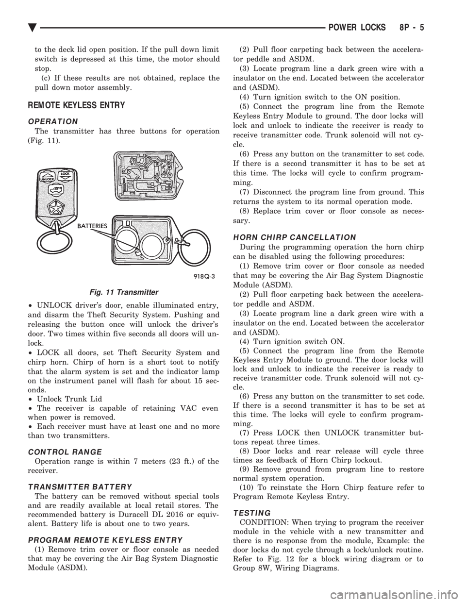
The transmitter has three buttons for operation
(Fig. 11).
² UNLOCK driver's door, enable illuminated entry,
and disarm the Theft Security System. Pushing and
releasing the button once will unlock the driver's
door. Two times within five seconds all doors will un-
lock.
² LOCK all doors, set Theft Security System and
chirp horn. Chirp of horn is a short toot to notify
that the alarm system is set and the indicator lamp
on the instrument panel will flash for about 15 sec-
onds.
² Unlock Trunk Lid
² The receiver is capable of retaining VAC even
when power is removed.
² Each receiver must have at least one and no more
than two transmitters.
CONTROL RANGE
Operation range is within 7 meters (23 ft.) of the
receiver.
TRANSMITTER BATTERY
The battery can be removed without special tools
and are readily available at local retail stores. The
recommended battery is Duracell DL 2016 or equiv-
alent. Battery life is about one to two years.
PROGRAM REMOTE KEYLESS ENTRY
(1) Remove trim cover or floor console as needed
that may be covering the Air Bag System Diagnostic
Module (ASDM). (2) Pull floor carpeting back between the accelera-
tor peddle and ASDM. (3) Locate program line a dark green wire with a
insulator on the end. Located between the accelerator
and (ASDM). (4) Turn ignition switch to the ON position.
(5) Connect the program line from the Remote
Keyless Entry Module to ground. The door locks will
lock and unlock to indicate the receiver is ready to
receive transmitter code. Trunk solenoid will not cy-
cle. (6) Press any button on the transmitter to set code.
If there is a second transmitter it has to be set at
this time. The locks will cycle to confirm program-
ming. (7) Disconnect the program line from ground. This
returns the system to its normal operation mode. (8) Replace trim cover or floor console as neces-
sary.
HORN CHIRP CANCELLATION
During the programming operation the horn chirp
can be disabled using the following procedures: (1) Remove trim cover or floor console as needed
that may be covering the Air Bag System Diagnostic
Module (ASDM). (2) Pull floor carpeting back between the accelera-
tor peddle and ASDM. (3) Locate program line a dark green wire with a
insulator on the end. Located between the accelerator
and (ASDM). (4) Turn ignition switch ON.
(5) Connect the program line from the Remote
Keyless Entry Module to ground. The door locks will
lock and unlock to indicate the receiver is ready to
receive transmitter code. Trunk solenoid will not cy-
cle. (6) Press any button on the transmitter to set code.
If there is a second transmitter it has to be set at
this time. The locks will cycle to confirm program-
ming. (7) Press LOCK then UNLOCK transmitter but-
tons repeat three times. (8) Door locks and rear release will cycle three
times as feedback of Horn Chirp lockout. (9) Remove ground from program line to restore
normal system operation. (10) To reinstate the Horn Chirp feature refer to
Program Remote Keyless Entry.
TESTING
CONDITION: When trying to program the receiver
module in the vehicle with a new transmitter and
there is no response from the module, Example: the
door locks do not cycle through a lock/unlock routine.
Refer to Fig. 12 for a block wiring diagram or to
Group 8W, Wiring Diagrams.
Fig. 11 Transmitter
Ä POWER LOCKS 8P - 5
Page 701 of 2438
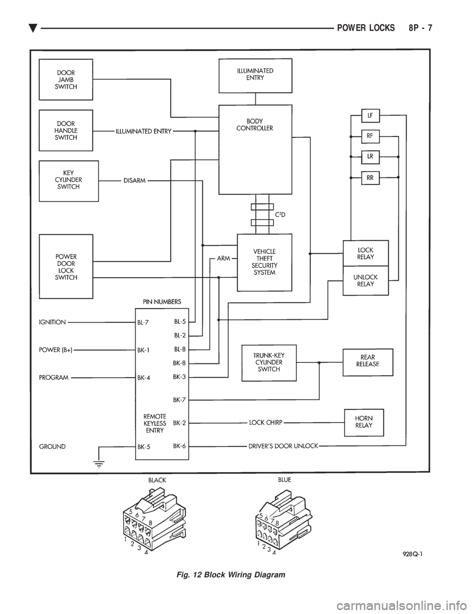
Fig. 12 Block Wiring Diagram
Ä POWER LOCKS 8P - 7
Page 727 of 2438
POWER WINDOWS
CONTENTS
page page
BENCH REPAIR OF REGULATOR AND MOTOR CONVENTIONAL REGULATORS .......... 5
GEAR AND PINION REPLACEMENT AND LUBRICATION ....................... 3
GENERAL INFORMATION .................. 1
MOTOR REPLACEMENT ................... 7
MOTOR REPLACEMENT CONVENTIONAL REGULATORS ....................... 3
MOTOR REPLACEMENTÐFLEX DRIVE REGULATORS ......................... 5 POWER WINDOW CABLE HOUSING/MOTOR RE-
PLACEMENTÐAC and AY BODIES ........ 7
QUARTER WINDOW MOTOR REPLACEMENTÐ AJ BODY ............................. 9
QUARTER WINDOW REPLACEMENTÐ AJ BODY ............................. 8
WINDOW LIFT MOTOR TEST .............. 1
WINDOW LIFT SWITCH TEST .............. 1
WIRING VOLTAGE TEST .................. 1
GENERAL INFORMATION
Front and rear door window lift motors are of the
permanent magnet type. A positive and negative bat-
tery connection to either of the two motor terminals
will cause the motor to rotate in one direction. Re-
versing current through these same two connections
will cause the motor to rotate in the opposite direc-
tion. Each individual motor is grounded through the
master switch by a black wire attached to the left
cowl panel. It is necessary that the window be free to slide up
and down in the glass channels or tubes and tracks.
If the window is not free to move up and down, the
window lift motor will not be able to move the glass. To determine if the glass is free is to disconnect the
regulator from the glass lift plate, and slide the win-
dow up and down by hand. For conventional arm-sec-
tor regulators, after the lift plate is detached from
the glass, it will slide off the regulator drive arm.
Flex-drive regulators may be detached the same way
or by removing one screw holding the flex rack to the
lift plate drive arm.
WIRING VOLTAGE TEST
The following wiring test determines whether or
not voltage is continuous through the body harness
to switch. After removing switch for testing purposes, care-
fully separate multiple terminal block on wiring har-
ness from switch body. With ignition switch ON
connect one lead of test light to black (or gray) wire
terminal and touch other test light lead to tan wire
terminal. If the test light comes on, the wiring cir-
cuit between the battery and switch is functional. If
light does not come on, check 30 amp main fuse (cir- cuit breaker) or for a broken wire. For wiring, spe-
cific connector type and location, refer to Group 8W,
Wiring Diagrams.
WINDOW LIFT SWITCH TEST
For switch testing, remove the switch from its
mounting. Using an ohmmeter, refer to Window
Switch Continuity Charts to determine if continuity
is correct. If the results are not obtained, replace the
switch. AC and AY Bodies are equipped with an Auto-
Down feature. This feature allows the operator to
lower the driver's window without having to hold the
switch in the down position. The Auto-Down feature
can be activated by pressing the down switch past
the first detent (Stop). To test the auto-down feature, operate the window
in the normal up and down mode. If the window
works correctly in the normal mode, but not in the
auto-down mode, replace the switch. To test the window switch (other than Auto-Down
mode), install a known good switch.
WINDOW LIFT MOTOR TEST
(1) Connect positive (+) lead from a test battery to
either of the two motor terminals. (2) Connect negative (-) lead from test battery to
remaining motor terminal. (3) The motor should now rotate in one direction to
either move window up or down. (a) If window happens to already be in full UP
position and motor is connected so as to rotate in
UP direction no movement will be observed. (b) Likewise, motor connected to DOWN direc-
tion rotation, no movement will be observed if win-
dow is already in full DOWN position.
Ä POWER WINDOWS 8S - 1
Page 743 of 2438
AUTOMATIC DAY/NIGHT INSIDE MIRROR
Operational test:
² Turn ignition switch to the ON position with the
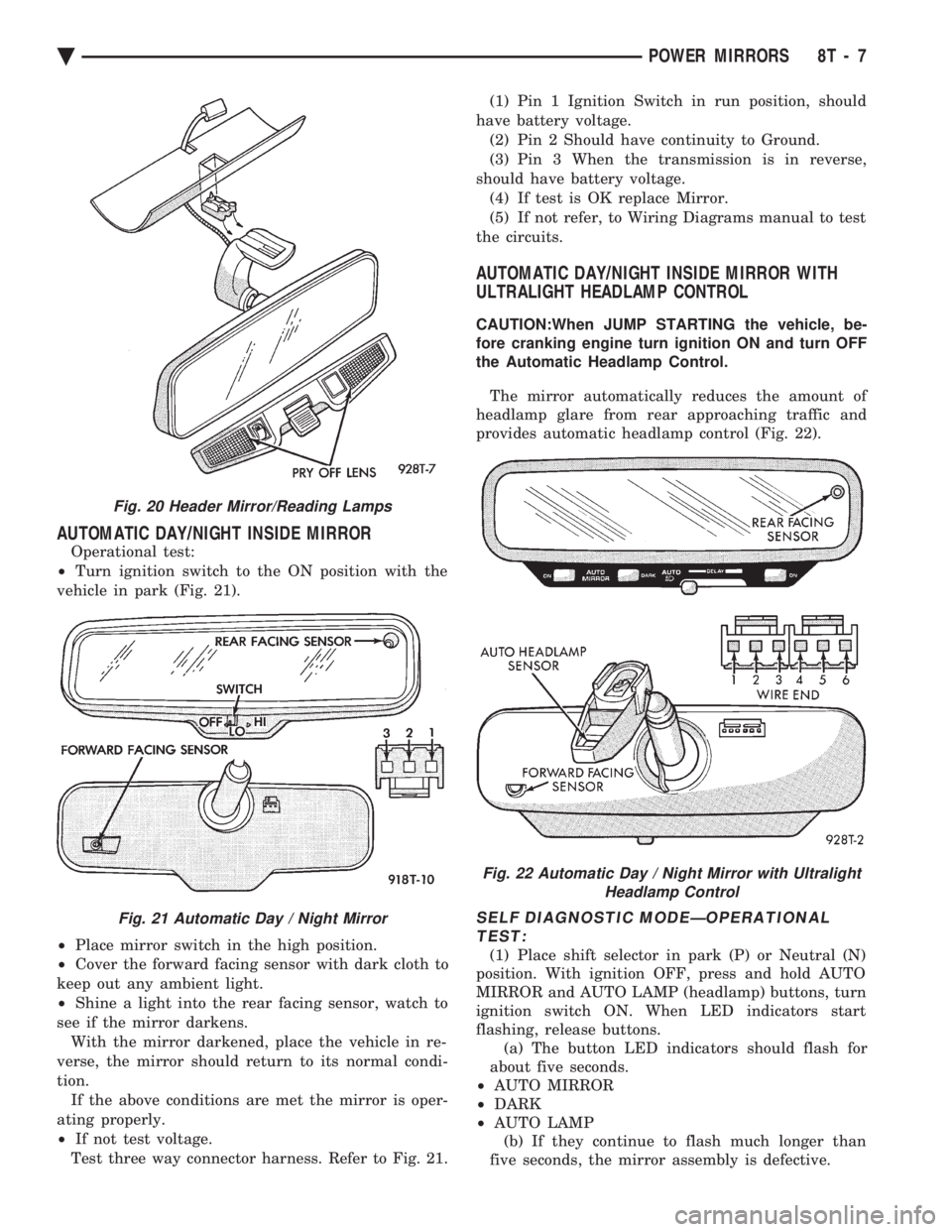
vehicle in park (Fig. 21).
² Place mirror switch in the high position.
² Cover the forward facing sensor with dark cloth to
keep out any ambient light.
² Shine a light into the rear facing sensor, watch to
see if the mirror darkens. With the mirror darkened, place the vehicle in re-
verse, the mirror should return to its normal condi-
tion. If the above conditions are met the mirror is oper-
ating properly.
² If not test voltage.
Test three way connector harness. Refer to Fig. 21. (1) Pin 1 Ignition Switch in run position, should
have battery voltage. (2) Pin 2 Should have continuity to Ground.
(3) Pin 3 When the transmission is in reverse,
should have battery voltage. (4) If test is OK replace Mirror.
(5) If not refer, to Wiring Diagrams manual to test
the circuits.
AUTOMATIC DAY/NIGHT INSIDE MIRROR WITH
ULTRALIGHT HEADLAMP CONTROL
CAUTION:When JUMP STARTING the vehicle, be-
fore cranking engine turn ignition ON and turn OFF
the Automatic Headlamp Control.
The mirror automatically reduces the amount of
headlamp glare from rear approaching traffic and
provides automatic headlamp control (Fig. 22).
SELF DIAGNOSTIC MODEÐOPERATIONAL TEST:
(1) Place shift selector in park (P) or Neutral (N)
position. With ignition OFF, press and hold AUTO
MIRROR and AUTO LAMP (headlamp) buttons, turn
ignition switch ON. When LED indicators start
flashing, release buttons. (a) The button LED indicators should flash for
about five seconds.
² AUTO MIRROR
² DARK
² AUTO LAMP
(b) If they continue to flash much longer than
five seconds, the mirror assembly is defective.
Fig. 20 Header Mirror/Reading Lamps
Fig. 21 Automatic Day / Night Mirror
Fig. 22 Automatic Day / Night Mirror with Ultralight Headlamp Control
Ä POWER MIRRORS 8T - 7