1993 CHEVROLET PLYMOUTH ACCLAIM tow
[x] Cancel search: towPage 95 of 2438

the plastic retaining collar. Carefully insert each of the
tripod rollers into the retaining collar, one at a time
while holding the interconnecting shaft on an angle.
Carefully push down on the shaft until the rollers are
locked into retaining collar in the housing.(4) Position the boot over the boot retaining groove
in the housing and clamp in place. See Boots Install.
S.S.G.
(1) Distribute 1/2 the amount of the grease provided
into the housing and the remaining amount into the
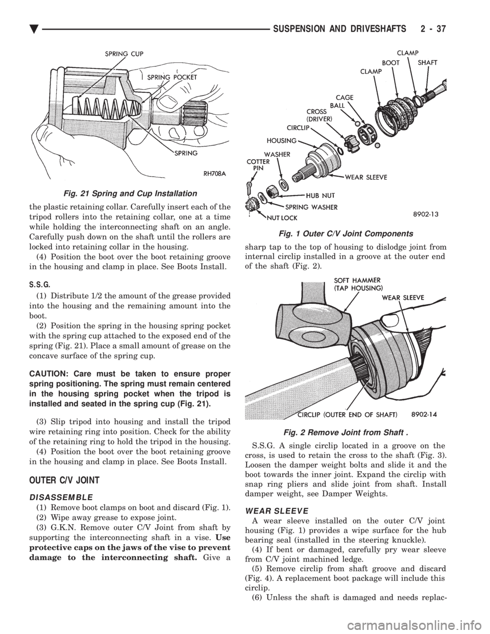
boot. (2) Position the spring in the housing spring pocket
with the spring cup attached to the exposed end of the
spring (Fig. 21). Place a small amount of grease on the
concave surface of the spring cup.
CAUTION: Care must be taken to ensure proper
spring positioning. The spring must remain centered
in the housing spring pocket when the tripod is
installed and seated in the spring cup (Fig. 21).
(3) Slip tripod into housing and install the tripod
wire retaining ring into position. Check for the ability
of the retaining ring to hold the tripod in the housing. (4) Position the boot over the boot retaining groove
in the housing and clamp in place. See Boots Install.
OUTER C/V JOINT
DISASSEMBLE
(1) Remove boot clamps on boot and discard (Fig. 1).
(2) Wipe away grease to expose joint.
(3) G.K.N. Remove outer C/V Joint from shaft by
supporting the interconnecting shaft in a vise. Use
protective caps on the jaws of the vise to prevent
damage to the interconnecting shaft. Give a sharp tap to the top of housing to dislodge joint from
internal circlip installed in a groove at the outer end
of the shaft (Fig. 2).
S.S.G. A single circlip located in a groove on the
cross, is used to retain the cross to the shaft (Fig. 3).
Loosen the damper weight bolts and slide it and the
boot towards the inner joint. Expand the circlip with
snap ring pliers and slide joint from shaft. Install
damper weight, see Damper Weights.WEAR SLEEVE
A wear sleeve installed on the outer C/V joint
housing (Fig. 1) provides a wipe surface for the hub
bearing seal (installed in the steering knuckle). (4) If bent or damaged, carefully pry wear sleeve
from C/V joint machined ledge. (5) Remove circlip from shaft groove and discard
(Fig. 4). A replacement boot package will include this
circlip. (6) Unless the shaft is damaged and needs replac-
Fig. 1 Outer C/V Joint Components
Fig. 2 Remove Joint from Shaft .
Fig. 21 Spring and Cup Installation
Ä SUSPENSION AND DRIVESHAFTS 2 - 37
Page 103 of 2438

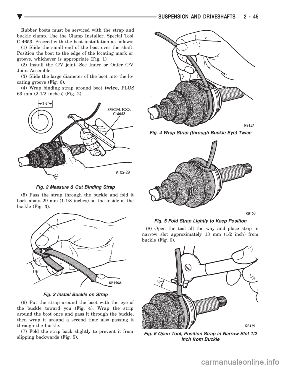
Rubber boots must be serviced with the strap and
buckle clamp. Use the Clamp Installer, Special Tool
C-4653. Proceed with the boot installation as follows: (1) Slide the small end of the boot over the shaft.
Position the boot to the edge of the locating mark or
groove, whichever is appropriate (Fig. 1). (2) Install the C/V joint. See Inner or Outer C/V
Joint Assemble. (3) Slide the large diameter of the boot into the lo-
cating groove (Fig. 6). (4) Wrap binding strap around boot twice, PLUS
63 mm (2-1/2 inches) (Fig. 2).
(5) Pass the strap through the buckle and fold it
back about 29 mm (1-1/8 inches) on the inside of the
buckle (Fig. 3).
(6) Put the strap around the boot with the eye of
the buckle toward you (Fig. 4). Wrap the strip
around the boot once and pass it through the buckle,
then wrap it around a second time also passing it
through the buckle. (7) Fold the strip back slightly to prevent it from
slipping backwards (Fig. 5). (8) Open the tool all the way and place strip in
narrow slot approximately 13 mm (1/2 inch) from
buckle (Fig. 6).
Fig. 2 Measure & Cut Binding Strap
Fig. 3 Install Buckle on Strap
Fig. 4 Wrap Strap (through Buckle Eye) Twice
Fig. 5 Fold Strap Lightly to Keep Position
Fig. 6 Open Tool, Position Strap in Narrow Slot 1/2 Inch from Buckle
Ä SUSPENSION AND DRIVESHAFTS 2 - 45
Page 105 of 2438

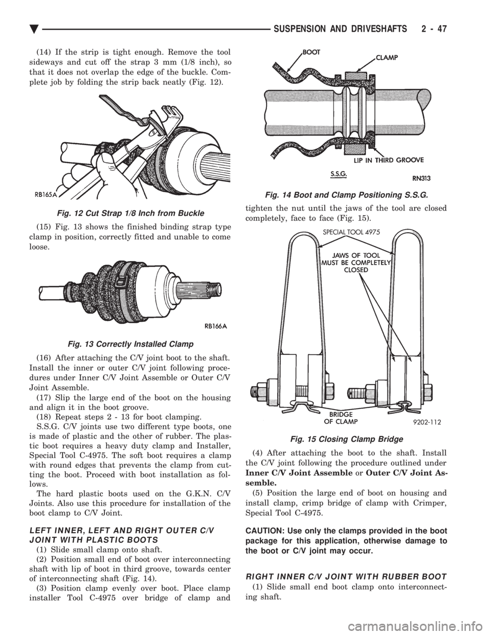
(14) If the strip is tight enough. Remove the tool
sideways and cut off the strap 3 mm (1/8 inch), so
that it does not overlap the edge of the buckle. Com-
plete job by folding the strip back neatly (Fig. 12).
(15) Fig. 13 shows the finished binding strap type
clamp in position, correctly fitted and unable to come
loose.
(16) After attaching the C/V joint boot to the shaft.
Install the inner or outer C/V joint following proce-
dures under Inner C/V Joint Assemble or Outer C/V
Joint Assemble. (17) Slip the large end of the boot on the housing
and align it in the boot groove. (18) Repeat step s2-13forboot clamping.
S.S.G. C/V joints use two different type boots, one
is made of plastic and the other of rubber. The plas-
tic boot requires a heavy duty clamp and Installer,
Special Tool C-4975. The soft boot requires a clamp
with round edges that prevents the clamp from cut-
ting the boot. Proceed with boot installation as fol-
lows. The hard plastic boots used on the G.K.N. C/V
Joints. Also use this procedure for installation of the
boot clamp to C/V Joint.
LEFT INNER, LEFT AND RIGHT OUTER C/V JOINT WITH PLASTIC BOOTS
(1) Slide small clamp onto shaft.
(2) Position small end of boot over interconnecting
shaft with lip of boot in third groove, towards center
of interconnecting shaft (Fig. 14). (3) Position clamp evenly over boot. Place clamp
installer Tool C-4975 over bridge of clamp and tighten the nut until the jaws of the tool are closed
completely, face to face (Fig. 15).
(4) After attaching the boot to the shaft. Install
the C/V joint following the procedure outlined under
Inner C/V Joint Assemble orOuter C/V Joint As-
semble. (5) Position the large end of boot on housing and
install clamp, crimp bridge of clamp with Crimper,
Special Tool C-4975.
CAUTION: Use only the clamps provided in the boot
package for this application, otherwise damage to
the boot or C/V joint may occur.
RIGHT INNER C/V JOINT WITH RUBBER BOOT
(1) Slide small end boot clamp onto interconnect-
ing shaft.
Fig. 12 Cut Strap 1/8 Inch from Buckle
Fig. 13 Correctly Installed Clamp
Fig. 14 Boot and Clamp Positioning S.S.G.
Fig. 15 Closing Clamp Bridge
Ä SUSPENSION AND DRIVESHAFTS 2 - 47
Page 118 of 2438

In addition, there is an air regeneration cycle that
is controlled by the Control Module (CM). If the
height sensor signal is in the neutral or high posi-
tion. When the ignition switch is turned to the ON
position, after a 22 to 28 second delay, the compres-
sor will run from 2 to 6 seconds. To prevent excessive cycling between the compres-
sor and the exhaust solenoid circuits during normal
ride conditions. A 12 to 18 second delay is incorpo-
rated in the microprocessor.
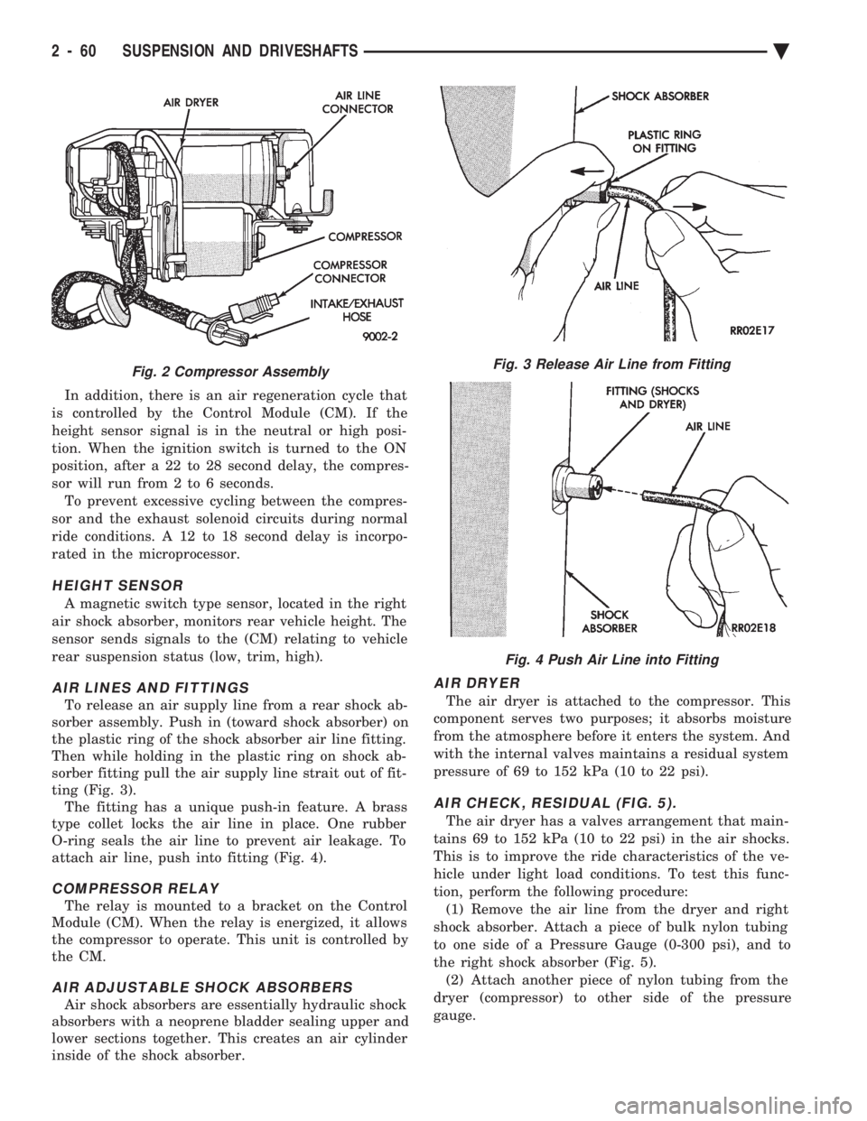
HEIGHT SENSOR
A magnetic switch type sensor, located in the right
air shock absorber, monitors rear vehicle height. The
sensor sends signals to the (CM) relating to vehicle
rear suspension status (low, trim, high).
AIR LINES AND FITTINGS
To release an air supply line from a rear shock ab-
sorber assembly. Push in (toward shock absorber) on
the plastic ring of the shock absorber air line fitting.
Then while holding in the plastic ring on shock ab-
sorber fitting pull the air supply line strait out of fit-
ting (Fig. 3). The fitting has a unique push-in feature. A brass
type collet locks the air line in place. One rubber
O-ring seals the air line to prevent air leakage. To
attach air line, push into fitting (Fig. 4).
COMPRESSOR RELAY
The relay is mounted to a bracket on the Control
Module (CM). When the relay is energized, it allows
the compressor to operate. This unit is controlled by
the CM.
AIR ADJUSTABLE SHOCK ABSORBERS
Air shock absorbers are essentially hydraulic shock
absorbers with a neoprene bladder sealing upper and
lower sections together. This creates an air cylinder
inside of the shock absorber.
AIR DRYER
The air dryer is attached to the compressor. This
component serves two purposes; it absorbs moisture
from the atmosphere before it enters the system. And
with the internal valves maintains a residual system
pressure of 69 to 152 kPa (10 to 22 psi).
AIR CHECK, RESIDUAL (FIG. 5).
The air dryer has a valves arrangement that main-
tains 69 to 152 kPa (10 to 22 psi) in the air shocks.
This is to improve the ride characteristics of the ve-
hicle under light load conditions. To test this func-
tion, perform the following procedure: (1) Remove the air line from the dryer and right
shock absorber. Attach a piece of bulk nylon tubing
to one side of a Pressure Gauge (0-300 psi), and to
the right shock absorber (Fig. 5). (2) Attach another piece of nylon tubing from the
dryer (compressor) to other side of the pressure
gauge.
Fig. 2 Compressor AssemblyFig. 3 Release Air Line from Fitting
Fig. 4 Push Air Line into Fitting
2 - 60 SUSPENSION AND DRIVESHAFTS Ä
Page 135 of 2438

AIR LINE FITTINGS
To remove an air supply line from an air compres-
sor assembly air line fitting. Push in (toward re-
ceiver dryer) on the plastic ring of the receiver dryer
air supply air line fitting. While holding in the air
line fitting on the receiver dryer pull the air supply
line strait out of the fitting (Fig. 6).
The fitting has a unique push-in feature. A brass
type collet locks the air line in place. One rubber
O-Ring seals the air line to prevent air leakage. To
attach air line, just push into fitting (Fig. 7).
AIR CHECK, RESIDUAL
The air dryer has a valving arrangement that
maintains 172 to 276 kPa (25 to 40 psi). To test this function, perform the following proce-
dure: (1) Remove the air line from the dryer and strut or
spring. Attach a piece of bulk nylon tubing to one
side of a Pressure Gauge (0-300 psi), and to the strut/
spring solenoid (Fig. 8). (2) Attach another piece of nylon tubing from the
dryer (compressor) to other side of the pressure
gauge. A compression ball sleeve nut and sleeve for 3/16
inch tubing with ball sleeve connector and an inter-
nal pipe T-fitting. Can be used to attach the tubing
to the pressure gauge. (3) Activate compressor by grounding pin 508 to
pin x 20 (See Control Module Connector), cycle unit
and read actual air pressure. Pressure of 172 to 276
kPa (25 to 40 psi) indicates that the system and com-
pressor is acceptable.
COMPRESSOR PERFORMANCE TEST
This test can be performed on the vehicle to evalu-
ate compressor current draw, pressure output, and
leak down. (1) Disconnect the compressor motor wiring har-
ness connector. (2) Disconnect air line between dryer and strut or
spring solenoid. (3) Connect an air pressure gauge into the system
(Fig. 8). (4) Connect an ammeter in series between the red
wire terminal on compressor connector and a 12 volt
power source. Also, connect a ground wire from the
black wire terminal on the compressor connector to a
good ground on the frame (Fig. 9) (5) If the current draw to the compressor motor ex-
ceeds 30 amperes, replace the compressor assembly.
AIR LEAK CHECK
(1) Check all air line to connector joints.
² Air line to compressor connectors.
² Air line to solenoid.
(2) Check the rubber membranes.
² Front struts.
² Rear springs.
Fig. 6 Release Air Line from Fitting
Fig. 7 Push Air Line into Fitting
Fig. 8 Pressure Gauge Installed in System
Ä SUSPENSION AND DRIVESHAFTS 2 - 77
Page 163 of 2438

(3) Position the tubing in the jaws of the Flaring
Tool so that it is flush with the top surface of the
flaring tool bar assembly. (See Fig. 17). (4) Install the correct size adaptor for the brake
tubing being flared, on the feed screw of the yoke as-
sembly. Center the yoke and adapter over the end of
the tubing. Apply lubricant to the adapter area that
contacts brake tubing. Making sure the adapter pilot
is fully inserted in the end of the brake tubing.
Screw in the feed screw of the yoke assembly until
the adaptor has seated squarely on the surface of the
bar assembly (Fig. 17). This process has created the
(metric) ISO tubing flare.STOP LAMP SWITCH ADJUSTMENT (ALL
VEHICLES)
The stop lamp switch incorporates a self adjusting
feature. If adjustment or replacement is required,
proceed as follows: Install the switch in the retaining
bracket and push the switch forward as far as it will
go. The brake pedal will move forward slightly (Fig.
18). Gently pull back on the brake pedal bringing the
striker back toward the switch until the brake pedal
will go back no further. This will cause the switch to
ratchet backward to the correct position. Very little
movement is required, and no further adjustment is
necessary.
Fig. 17 ISO Tubing Flare ProcessFig. 18 Stop Lamp Switch
BASIC DIAGNOSIS GUIDE
Ä BRAKES 5 - 13
Page 171 of 2438

If old springs have overheated or are damaged, re-
place. Overheating indications are paint discoloration
or distorted end coils. Varga brake springs are not
painted but overheating of the brake springs will be
noted by any Blueing of the springs.
BRAKE SHOE INSTALLATION
Lubricate the eight shoe contact areas on the sup-
port plate and anchor using Mopar Multi-Purpose
Lubricant or equivalent (Fig. 11).
KELSEY HAYES REASSEMBLE
Assemble the park brake lever and wave washer to
the new replacement shoe (Fig. 9). Attach upper return spring between the two new
shoe assemblies. Apply a small amount of Mopar Multi-Purpose Lu-
bricant or equivalent to the automatic adjuster screw
assembly. Install adjuster with the two stepped forks
facing toward the outboard side of the shoes (Fig.
10). The longer fork will be pointing to the rear. Connect the lower shoe to shoe spring. Expand the automatic adjuster so that the end of the
shoes will clear the wheel cylinder boots. Position the
brake shoe assemblies on support plate and install
holddown springs (Fig. 7). Install self adjuster lever and spring.
Connect park brake cable.
Adjust brake shoes so that they will not interfere
with the drum installation.
CAUTION: Make sure the adjuster screw nut contacts
the adjuster tubular strut.
Install the drums and pump the brake pedal
several times to partially complete the shoe ad-
justment. After adjusting the Parking brake cable (see Adjust-
ing Parking Brake), road test vehicle. The automatic
adjuster will continue the brake adjustment during the
test.
VARGA REASSEMBLE
(1) Install park brake cable in park brake lever of
trailing shoe. (2) Attach trailing shoe, then leading shoe lower
springs to shoes and anchor plate. (3) Position shoes on support plate and install hold-
down springs. (4) Install automatic adjusters. Left side adjuster
has left hand threads and right side adjuster has
right-hand threads. Do not interchange sides.
Make sure adjuster is installed correctly. (Adjuster
ends must be above extruded pins in web of shoe as
shown in Fig. 3). (5) Install upper shoe to shoe spring. Ensure that
the spring terminal ends are fully engaged in the shoe
webs. (6) Rotate serrated adjuster nut to remove free play
from the adjuster assembly. (7) Install the adjuster lever on the leading shoe
pivot pin. Then attach the short end of the adjuster
spring into the hole on the lever. Then install the long
end of the spring in the leading shoe hole. (8) Connect park brake cable and adjust brake shoes
so as not to interfere with drum installation.
BRAKE DRUM REFACING
Measure drum runout and diameter. If not to speci-
fication, reface drum. (Runout should not exceed
0.1524 mm or 0.006 inch). The diameter variation (oval
shape) of the drum braking surface must not exceed
either 0.0635 mm (0.0025 inch) in 30É or 0.0889 mm
(0.0035 inch) in 360É. All drums will show markings of maximum allowable
diameter (Fig. 12).
Fig. 10 Adjuster Screw and Lever (Typical)
Fig. 11 Shoe Contact Areas on Support Plate
Ä BRAKES 5 - 21
Page 220 of 2438

(7) Unfasten brackets on steel heater water line at
dash panel and left frame rail. On Manual Transmis-
sion vehicles, unfasten clutch cable bracket at shock
tower and move aside. (8) Slide the power brake unit up and to the left
(mounting holes are slotted) on the dash panel, then
tilt inboard and up to remove.
CAUTION: Do not attempt to disassemble power
brake unit as this booster is serviced ONLY as a
complete assembly.
INSTALL (1) Position power brake booster onto dash panel.
(2) Install and tighten the 4 power brake booster to
dash panel mounting nuts (Fig. 5) to 29 N Im (250 in.
lbs.) torque. (3) Install steel heater water line and clutch cable
bracket, if so equipped. (4) Carefully position master cylinder on power
brake unit. (5) Install and tighten the 2 master cylinder to
power booster mounting nuts (Fig. 4) to 29 N Im (250
in. lbs.) torque. (6) Connect vacuum hose onto the check valve, lo-
cated on the power brake unit. (7) Using lubriplate, or equivalent, coat the bearing
surface of pedal pin (Fig. 5). (8) Connect power brake booster input rod to brake
pedal pin and install a NEW retainer clip. Use only a
new retainer clip DO NOT USE the old clip. (9) Check stop light operation.
WHEEL BEARINGS
FRONT WHEEL BEARINGS
Front wheel drive vehicles are equipped with per-
manently sealed front wheel bearings. There is no
periodic lubrication or maintenance recommended for
these units. However if during servicing of the brake
system, service to the front wheel bearing is required
refer to Group 2, Suspension in this service manual.
REAR WHEEL BEARINGS
NORMAL SERVICE
The lubricant in the rear wheel bearings should be
inspected whenever the hubs are removed to inspect
or service the brake system. Or at least every 30,000
miles (48,000 km). The bearings should be cleaned
and repacked with a High Temperature Multipurpose
E.P. Grease whenever the disc brake rotors are re-
surfaced.
INSPECTION
Check lubricant to see that it is adequate in quan-
tity and quality. If the grease is low in quantity, con-
tains dirt, appears dry or has been contaminated
with water, it will appear milky. The bearings then must be cleaned and repacked.
Do not add grease to
a wheel bearing that already has grease packed
in it. Relubricate completely. Mixing of different
types of greases in wheel bearings should be
avoided since it may result in excessive thinning
and leakage of the grease.
REMOVAL AND INSTALLATION
For the servicing, removal and installation of the
rear wheel bearings follow the procedure listed below. (1) Remove the rear tire and wheel assembly.
(2) On rear disc brake equipped vehicles remove the
caliper and rotor. Support the caliper out of the way.
Do not allow the caliper to hang by the hydraulic
hose. See disc brake section in this group for caliper
removal procedure. (3) Remove grease cap, cotter pin, nut lock, nut,
thrust washer and outer wheel bearing. (4) Carefully slide hub or drum from spindle. Do not
drag inner bearing or grease seal over stub axle
(thread, bearing, and oil seal may be damaged.) Using
an appropriate tool remove the grease seal and inner
bearing from the drum or hub. Discard grease
Fig. 5 Power Brake Booster Mounting
5 - 70 BRAKES Ä