1993 CHEVROLET PLYMOUTH ACCLAIM tow
[x] Cancel search: towPage 270 of 2438
DIAGNOSTIC CONNECTOR
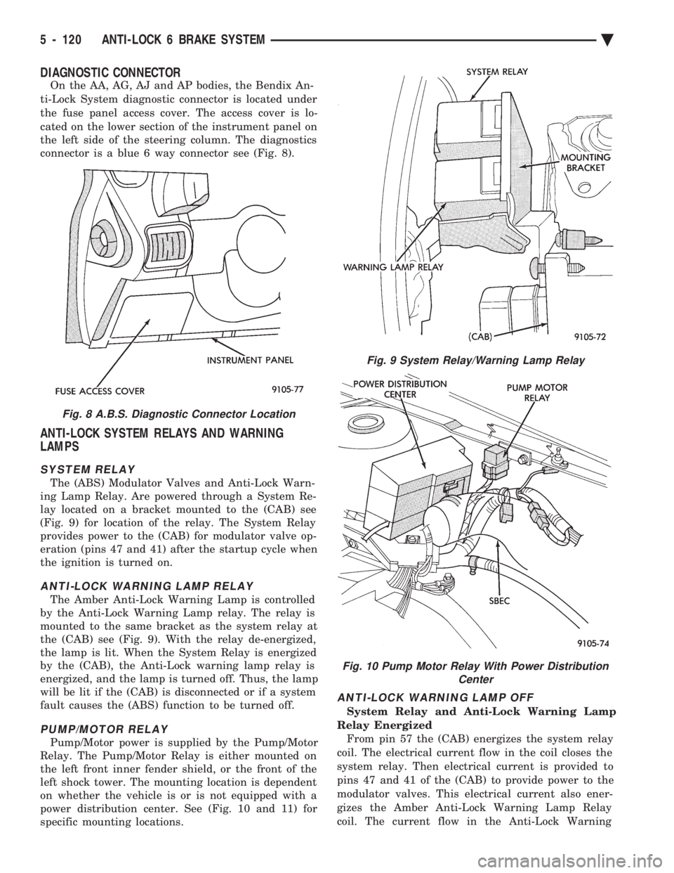
On the AA, AG, AJ and AP bodies, the Bendix An-
ti-Lock System diagnostic connector is located under
the fuse panel access cover. The access cover is lo-
cated on the lower section of the instrument panel on
the left side of the steering column. The diagnostics
connector is a blue 6 way connector see (Fig. 8).
ANTI-LOCK SYSTEM RELAYS AND WARNING
LAMPS
SYSTEM RELAY
The (ABS) Modulator Valves and Anti-Lock Warn-
ing Lamp Relay. Are powered through a System Re-
lay located on a bracket mounted to the (CAB) see
(Fig. 9) for location of the relay. The System Relay
provides power to the (CAB) for modulator valve op-
eration (pins 47 and 41) after the startup cycle when
the ignition is turned on.
ANTI-LOCK WARNING LAMP RELAY
The Amber Anti-Lock Warning Lamp is controlled
by the Anti-Lock Warning Lamp relay. The relay is
mounted to the same bracket as the system relay at
the (CAB) see (Fig. 9). With the relay de-energized,
the lamp is lit. When the System Relay is energized
by the (CAB), the Anti-Lock warning lamp relay is
energized, and the lamp is turned off. Thus, the lamp
will be lit if the (CAB) is disconnected or if a system
fault causes the (ABS) function to be turned off.
PUMP/MOTOR RELAY
Pump/Motor power is supplied by the Pump/Motor
Relay. The Pump/Motor Relay is either mounted on
the left front inner fender shield, or the front of the
left shock tower. The mounting location is dependent
on whether the vehicle is or is not equipped with a
power distribution center. See (Fig. 10 and 11) for
specific mounting locations.
ANTI-LOCK WARNING LAMP OFF
System Relay and Anti-Lock Warning Lamp
Relay Energized From pin 57 the (CAB) energizes the system relay
coil. The electrical current flow in the coil closes the
system relay. Then electrical current is provided to
pins 47 and 41 of the (CAB) to provide power to the
modulator valves. This electrical current also ener-
gizes the Amber Anti-Lock Warning Lamp Relay
coil. The current flow in the Anti-Lock Warning
Fig. 8 A.B.S. Diagnostic Connector Location
Fig. 9 System Relay/Warning Lamp Relay
Fig. 10 Pump Motor Relay With Power Distribution Center
5 - 120 ANTI-LOCK 6 BRAKE SYSTEM Ä
Page 287 of 2438
BRAKES
CONTENTS
page page
BENDIX ANTILOCK 4 BRAKE SYSTEM ...... 12
GENERAL INFORMATION .................. 1 HYDRAULIC SYSTEM CONTROL VALVES . . . 10
SERVICE ADJUSTMENTS
.................. 3
GENERAL INFORMATION
Throughout this group, references may be made to
a particular vehicle by letter or number designation.
A chart showing the break down of these designa-
tions is included in the Introduction Section at the
front of this service manual. Standard brake equipment consists of:
² Double pin floating caliper disc front brakes.
² Rear automatic adjusting drum brakes.
² Differential valve with a brake warning switch.
² Master cylinder.
² Vacuum power booster.
² Double pin floating caliper rear disc brakes are
available on some models. The Bendix Antilock 4 Brake System, uses the fol-
lowing standard brake system components. Master
cylinder, power booster, caliper assemblies, braking
discs, pedal assembly, brake lines and hoses. The
unique parts of the Bendix Antilock 4 Brake System
consists of the following components, modulator as-
sembly, unique proportioning valves, unique junction
block, wheel speed sensors, tone wheels, and elec-
tronic control unit. These components will be de-
scribed in detail in the Bendix Antilock 4 Brake
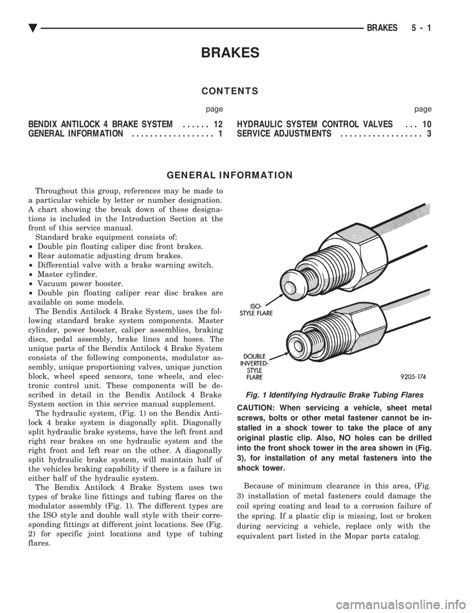
System section in this service manual supplement. The hydraulic system, (Fig. 1) on the Bendix Anti-
lock 4 brake system is diagonally split. Diagonally
split hydraulic brake systems, have the left front and
right rear brakes on one hydraulic system and the
right front and left rear on the other. A diagonally
split hydraulic brake system, will maintain half of
the vehicles braking capability if there is a failure in
either half of the hydraulic system. The Bendix Antilock 4 Brake System uses two
types of brake line fittings and tubing flares on the
modulator assembly (Fig. 1). The different types are
the ISO style and double wall style with their corre-
sponding fittings at different joint locations. See (Fig.
2) for specific joint locations and type of tubing
flares. CAUTION: When servicing a vehicle, sheet metal
screws, bolts or other metal fastener cannot be in-
stalled in a shock tower to take the place of any
original plastic clip. Also, NO holes can be drilled
into the front shock tower in the area shown in (Fig.
3), for installation of any metal fasteners into the
shock tower.
Because of minimum clearance in this area, (Fig.
3) installation of metal fasteners could damage the
coil spring coating and lead to a corrosion failure of
the spring. If a plastic clip is missing, lost or broken
during servicing a vehicle, replace only with the
equivalent part listed in the Mopar parts catalog.
Fig. 1 Identifying Hydraulic Brake Tubing Flares
Ä BRAKES 5 - 1
Page 288 of 2438
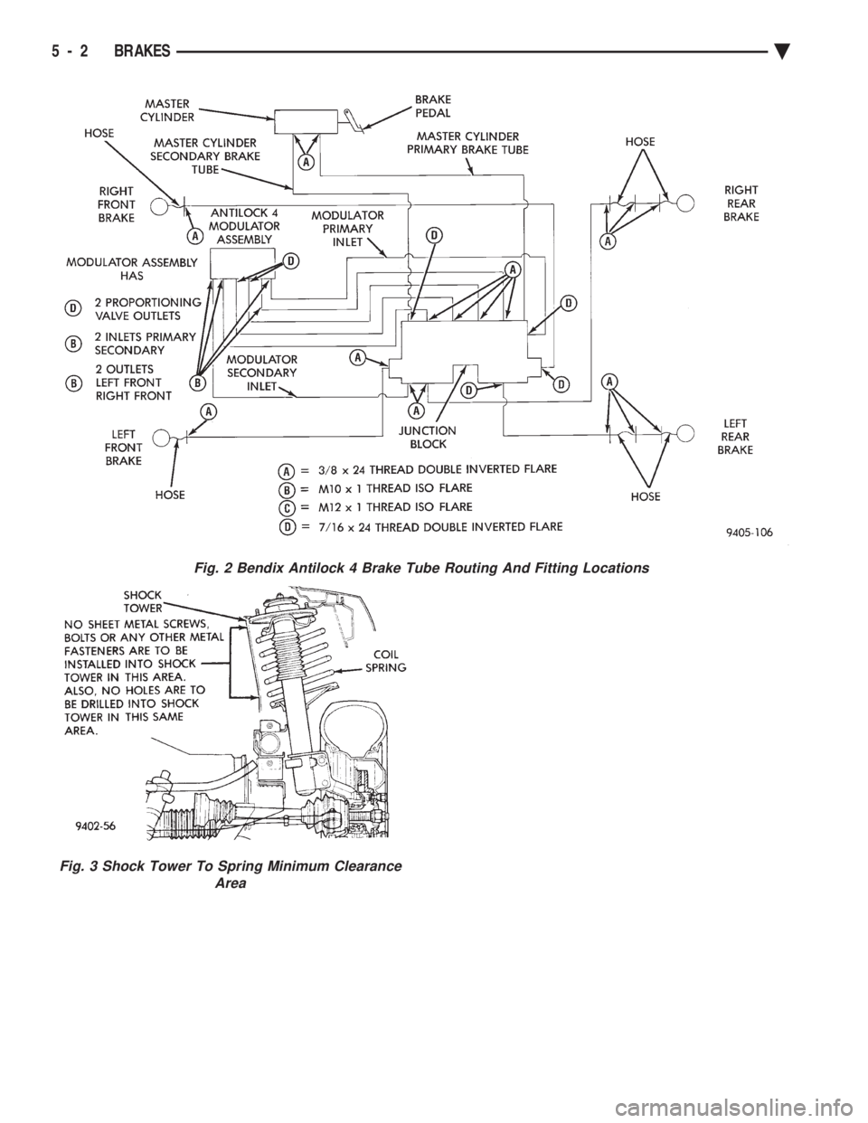
Fig. 2 Bendix Antilock 4 Brake Tube Routing And Fitting Locations
Fig. 3 Shock Tower To Spring Minimum Clearance Area
5 - 2 BRAKES Ä
Page 306 of 2438
ANTILOCK WARNING LAMP DIODE
The Warning Lamp Relay on the Bendix Antilock
4 Brake System has been replaced with a diode. The
diode is used to control the function of the warning
lamp and is located inside the CAB module wiring
harness. The diode is a replaceable component of the
wiring harness, and will not require replacement of
the entire wiring harness if only the diode is diag-
nosed to have failed. When the system relay is de-energized, the Anti-
lock warning lamp will be lit. This will occur because
a ground path exists for the Antilock warning lamp
through the Antilock warning lamp diode and the
system relay armature. When the system relay is en-
ergized by the CAB, the system relay armature will
no longer provide a ground and the lamp will turn
off. Thus, the lamp will be lit if either the CAB is
disconnected or a system fault causes the Antilock to
be turned off.
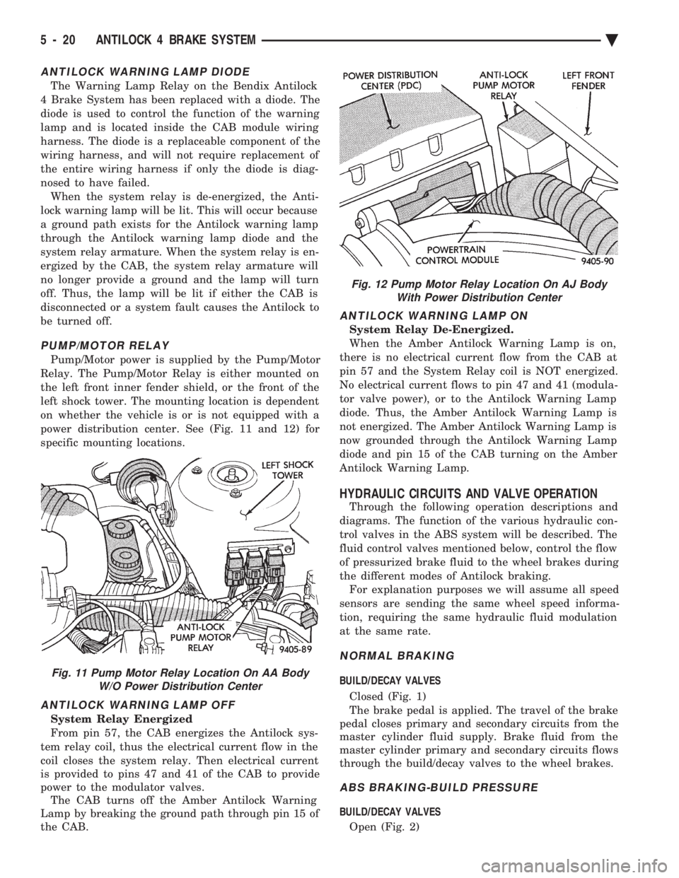
PUMP/MOTOR RELAY
Pump/Motor power is supplied by the Pump/Motor
Relay. The Pump/Motor Relay is either mounted on
the left front inner fender shield, or the front of the
left shock tower. The mounting location is dependent
on whether the vehicle is or is not equipped with a
power distribution center. See (Fig. 11 and 12) for
specific mounting locations.
ANTILOCK WARNING LAMP OFF
System Relay Energized
From pin 57, the CAB energizes the Antilock sys-
tem relay coil, thus the electrical current flow in the
coil closes the system relay. Then electrical current
is provided to pins 47 and 41 of the CAB to provide
power to the modulator valves. The CAB turns off the Amber Antilock Warning
Lamp by breaking the ground path through pin 15 of
the CAB.
ANTILOCK WARNING LAMP ON
System Relay De-Energized.
When the Amber Antilock Warning Lamp is on,
there is no electrical current flow from the CAB at
pin 57 and the System Relay coil is NOT energized.
No electrical current flows to pin 47 and 41 (modula-
tor valve power), or to the Antilock Warning Lamp
diode. Thus, the Amber Antilock Warning Lamp is
not energized. The Amber Antilock Warning Lamp is
now grounded through the Antilock Warning Lamp
diode and pin 15 of the CAB turning on the Amber
Antilock Warning Lamp.
HYDRAULIC CIRCUITS AND VALVE OPERATION
Through the following operation descriptions and
diagrams. The function of the various hydraulic con-
trol valves in the ABS system will be described. The
fluid control valves mentioned below, control the flow
of pressurized brake fluid to the wheel brakes during
the different modes of Antilock braking. For explanation purposes we will assume all speed
sensors are sending the same wheel speed informa-
tion, requiring the same hydraulic fluid modulation
at the same rate.
NORMAL BRAKING
BUILD/DECAY VALVES
Closed (Fig. 1)
The brake pedal is applied. The travel of the brake
pedal closes primary and secondary circuits from the
master cylinder fluid supply. Brake fluid from the
master cylinder primary and secondary circuits flows
through the build/decay valves to the wheel brakes.
ABS BRAKING-BUILD PRESSURE
BUILD/DECAY VALVES
Open (Fig. 2)
Fig. 11 Pump Motor Relay Location On AA Body W/O Power Distribution Center
Fig. 12 Pump Motor Relay Location On AJ BodyWith Power Distribution Center
5 - 20 ANTILOCK 4 BRAKE SYSTEM Ä
Page 334 of 2438

CLUTCH PEDAL NOISE/POP
The mechanism which automatically adjusts the
clutch cable to compensate for clutch wear may emit
a loud clicking or pop noise under certain circum-
stances. The cause of this noise in most cases is the clutch
cable auto-adjust spring being below design load
specifications. The condition can be corrected by ei-
ther bending the auto-adjust spring to bring it back
to specifications or replacing the spring (Fig. 1). The auto-adjust spring is located on the back of the
clutch pedal.
CLUTCH CABLE REPLACEMENT
(1) Remove retainer from clutch release lever at
transaxle by pulling on the tail of the ball stud (Fig.
2). (2) Pry out ball end of cable from positioner ad-
juster and remove cable, passing it through the hoop
in the shock tower mounting bracket. (3) Inspect cable for wear and contamination. The
inner cable strand should move smoothly inside the
cable housing. If cable is worn or damaged, replace
the cable. Do not lubricate.
(4) Inspect the clutch pedal and adjuster mecha- nism for wear. Apply a multipurpose lubricant on
parts indicated (Fig. 2). (5) To install, reverse procedure of steps (3)
through (1). (6) After installation, push and lift the clutch
pedal 2 or 3 times to allow adjuster mechanism to
function. (7) Check clutch pedal position switch operation.
Fig. 1 Clutch Cable Auto-Adjust Spring
6 - 2 MANUAL TRANSAXLE CLUTCH Ä
Page 360 of 2438

RADIATOR PRESSURE CAP
Radiators are equipped with a pressure cap which
releases pressure at some point within a range of
97-124 kPa (14-18 psi) (Fig. 7). The system will operate at higher than atmospheric
pressure which raises the coolant boiling point allow-
ing increased radiator cooling capacity. There is also a vent valve in the center of the cap that
allows a small coolant flow to the CRS tank. If valve is
stuck shut, the radiator hoses will be collapsed
on cool down. Clean the vent valve (Fig. 7) to
ensure proper sealing when boiling point is
reached.
There is also a gasket in the cap to seal to the top of
the filler neck so that vacuum can be maintained for
drawing coolant back into the radiator from the coolant
reserve system tank.
RADIATOR CAP TO FILLER NECK SEAL PRES- SURE RELIEF CHECK
The pressure cap upper gasket (seal) pressure relief
can be checked by removing the overflow hose at the
radiator filler neck nipple (Fig. 7). Attach the Radiator
Pressure Tool to the filler neck nipple and pump air
into the radiator. Pressure cap upper gasket should
relieve at 69-124 kPa (10-18 psi) and hold pressure at
55 kPa (8 psi) minimum.
WARNING: THE WARNING WORDS DO NOT OPEN
HOT ON THE RADIATOR PRESSURE CAP IS A
SAFETY PRECAUTION. WHEN HOT, PRESSURE
BUILDS UP IN COOLING SYSTEM. TO PREVENT
SCALDING OR INJURY, THE RADIATOR CAP
SHOULD NOT BE REMOVED WHILE THE SYSTEM IS
HOT AND/OR UNDER PRESSURE.
There is no need to remove the radiator cap at any
time except for the following purposes:
(1) Check and adjust antifreeze freeze point.
(2) Refill system with new antifreeze.
(3) Conducting service procedures.
(4) Checking for vacuum leaks.
WARNING: IF VEHICLE HAS BEEN RUN RECENTLY,
WAIT 15 MINUTES BEFORE REMOVING CAP. THEN PLACE A SHOP TOWEL OVER THE CAP AND WITH-
OUT PUSHING DOWN ROTATE IT COUNTER-
CLOCKWISE TO THE FIRST STOP. ALLOW FLUIDS
TO ESCAPE THROUGH THE OVERFLOW TUBE AND
WHEN THE SYSTEM STOPS PUSHING COOLANT
AND STEAM INTO THE CRS TANK AND PRESSURE
DROPS PUSH DOWN AND REMOVE THE CAP COM-
PLETELY. SQUEEZING THE RADIATOR INLET HOSE
WITH A SHOP TOWEL (TO CHECK PRESSURE) BE-
FORE AND AFTER TURNING TO THE FIRST STOP IS
RECOMMENDED.
PRESSURE TESTING RADIATOR CAPS
Dip the pressure cap in water, clean any deposits off
the vent valve or its seat and apply cap to end of
Radiator Pressure Tool. Working the plunger, bring the
pressure to 104 kPa (15 psi) on the gauge. If the
pressure cap fails to hold pressure of at least 97 kPa
(14 psi) replace cap. See CAUTION
If the pressure cap tests properly while positioned on
Radiator Pressure Tool, but will not hold pressure or
vacuum when positioned on the radiator. Inspect the
radiator filler neck and cap top gasket for irregularities
that may prevent the cap from sealing properly.
CAUTION: Radiator Pressure Tool is very sensitive to
small air leaks which will not cause cooling system
problems. A pressure cap that does not have a
history of coolant loss should not be replaced just
because it leaks slowly when tested with this tool.
Add water to the tool. Turn tool upside down and
recheck pressure cap to confirm that cap is bad.
INSPECTION
Hold the cap in hand, right side up(Fig. 7). The
vent valve at the bottom of the cap should open. If the
rubber gasket has swollen and prevents the valve from
opening, replace the cap. Hold the cleaned cap in hand upside down.If any
light can be seen between vent valve and rubber
gasket, replace cap. Do not use a replacement cap
that has a spring to hold the vent shut. Replacement cap must be of the type designed for
coolant reserve systems. This design assures coolant
return to radiator.
RADIATORS
The radiators are crossflow types (horizontal tubes)
with design features that provide greater strength as
well as sufficient heat transfer capabilities to keep the
engine satisfactorily cooled.
CAUTION: Plastic tanks, while stronger then brass
are subject to damage by impact, such as wrenches.
Fig. 7 Radiator Pressure Cap Filler Neck
7 - 18 COOLING SYSTEM Ä
Page 382 of 2438
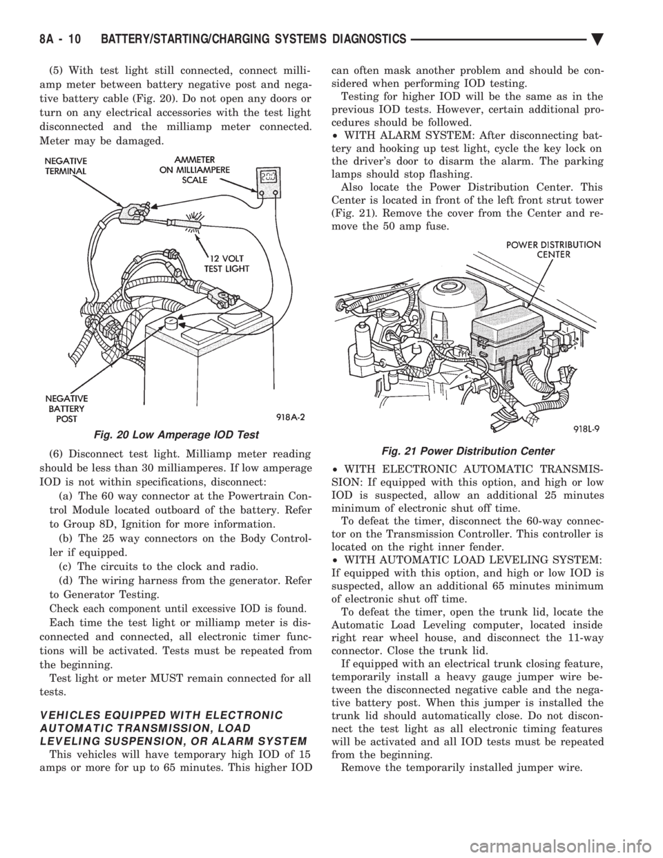
(5) With test light still connected, connect milli-
amp meter between battery negative post and nega-
tive battery cable (Fig. 20). Do not open any doors or
turn on any electrical accessories with the test light
disconnected and the milliamp meter connected.
Meter may be damaged.
(6) Disconnect test light. Milliamp meter reading
should be less than 30 milliamperes. If low amperage
IOD is not within specifications, disconnect: (a) The 60 way connector at the Powertrain Con-
trol Module located outboard of the battery. Refer
to Group 8D, Ignition for more information. (b) The 25 way connectors on the Body Control-
ler if equipped. (c) The circuits to the clock and radio.
(d) The wiring harness from the generator. Refer
to Generator Testing.
Check each component until excessive IOD is found.
Each time the test light or milliamp meter is dis-
connected and connected, all electronic timer func-
tions will be activated. Tests must be repeated from
the beginning. Test light or meter MUST remain connected for all
tests.
VEHICLES EQUIPPED WITH ELECTRONIC AUTOMATIC TRANSMISSION, LOADLEVELING SUSPENSION, OR ALARM SYSTEM
This vehicles will have temporary high IOD of 15
amps or more for up to 65 minutes. This higher IOD can often mask another problem and should be con-
sidered when performing IOD testing. Testing for higher IOD will be the same as in the
previous IOD tests. However, certain additional pro-
cedures should be followed.
² WITH ALARM SYSTEM: After disconnecting bat-
tery and hooking up test light, cycle the key lock on
the driver's door to disarm the alarm. The parking
lamps should stop flashing. Also locate the Power Distribution Center. This
Center is located in front of the left front strut tower
(Fig. 21). Remove the cover from the Center and re-
move the 50 amp fuse.
² WITH ELECTRONIC AUTOMATIC TRANSMIS-
SION: If equipped with this option, and high or low
IOD is suspected, allow an additional 25 minutes
minimum of electronic shut off time. To defeat the timer, disconnect the 60-way connec-
tor on the Transmission Controller. This controller is
located on the right inner fender.
² WITH AUTOMATIC LOAD LEVELING SYSTEM:
If equipped with this option, and high or low IOD is
suspected, allow an additional 65 minutes minimum
of electronic shut off time. To defeat the timer, open the trunk lid, locate the
Automatic Load Leveling computer, located inside
right rear wheel house, and disconnect the 11-way
connector. Close the trunk lid. If equipped with an electrical trunk closing feature,
temporarily install a heavy gauge jumper wire be-
tween the disconnected negative cable and the nega-
tive battery post. When this jumper is installed the
trunk lid should automatically close. Do not discon-
nect the test light as all electronic timing features
will be activated and all IOD tests must be repeated
from the beginning. Remove the temporarily installed jumper wire.
Fig. 20 Low Amperage IOD Test
Fig. 21 Power Distribution Center
8A - 10 BATTERY/STARTING/CHARGING SYSTEMS DIAGNOSTICS Ä
Page 387 of 2438

STARTER CONTROL CIRCUIT TESTS
The starter control circuit has:
² Starter solenoid
² Starter relay (Fig. 2)
² Neutral starting and back-up switch with auto-
matic transmissions
² Clutch pedal mounted starter interlock switch
with manual transmissions
² Ignition switch
² Battery
² All related wiring and connections
CAUTION: Before performing any starter tests, the
ignition system must be disabled.
² VEHICLES EQUIPPED WITH A CONVEN-
TIONAL DISTRIBUTOR: Disconnect coil wire from
distributor cap center tower. Secure wire to a good
ground to prevent engine from starting (Fig. 6).
² VEHICLES EQUIPPED WITH DIRECT IGNI-
TION SYSTEM: Unplug the coils electrical connector
(Fig. 7).
STARTER SOLENOID TEST
WARNING: CHECK TO ENSURE THAT THE TRANS-
MISSION IS IN PARK OR NEUTRAL WITH THE
PARKING BRAKE APPLIED
(1) Verify battery condition. Battery must be in
good condition with a full charge before performing
any starter tests. Refer to Battery Tests. (2) Perform this starter solenoid test BEFORE per-
forming the starter relay test. (3) Raise the vehicle.
(4) Perform a visual inspection of the starter/
starter solenoid for corrosion, loose connections or
faulty wiring. (5) Lower the vehicle.
(6) Locate the starter relay as follows:
² On AC, AG, AJ and AY Bodies the relay is located
in the Power Distribution Center. This Center is mounted near the front of the left front strut tower
(Fig. 13). The position of the starter relay within this
Center will be shown on the Center cover.
² On AA/AP Bodies the relay is located on the front
of the left front strut tower (Fig. 14).
(7) Remove the starter relay from the connector.
(8) Connect a remote starter switch or a jumper
wire between the battery positive post and terminal
87 on the starter relay connector. To decide the
starter relay terminal numbers, refer to the Starter
Relay Tests.
² If engine now cranks, starter/starter solenoid is
good. Go to the starter relay test.
² If engine does not crank with this test, or solenoid
chatters, check wiring and connectors from starter
Fig. 12 Test Positive Battery Cable Resistance
Fig. 13 Starter Relay LocationÐAC, AG, AJ, and AY Bodies
Fig. 14 Starter Relay LocationÐAA/AP Body
Ä BATTERY/STARTING/CHARGING SYSTEMS DIAGNOSTICS 8A - 15