1993 CHEVROLET PLYMOUTH ACCLAIM brake sensor
[x] Cancel search: brake sensorPage 222 of 2438

ANTI-LOCK BRAKE SYSTEMÐBENDIX ANTI-LOCK 10 AC/Y BODY INDEX
page page
ABS Brake System Diagnostic Features ....... 92
ABS Braking System Diagnosis .............. 87
ABS Controller Anti-Lock Brake (CAB) Service Precautions ........................... 88
ABS Equipped Vehicle Performance .......... 75
ABS Hydraulic Circuits and Valve Operation .... 85
ABS System Diagnostic Connector ........... 82
ABS System General Service Precautions ...... 88
ABS System Self-Diagnostics ............... 75
ABS Warning Systems Operation ............ 75
Anti-Lock Brake System Components ......... 76 Anti-Lock Brake System Definitions
........... 72
Anti-Lock Operation and Performance ......... 73
Anti-Lock System Relays and Warning Lamps . . . 82
Controller Anti-Lock Brake (CAB) ............. 80
Electronic Components ................... 103
General Information ....................... 72
General Service Precautions ................ 93
Major ABS Components ................... 73
Mechanical Diagnostics and Service Procedures . 89
Normal Braking System Function ............. 72
On Car Hydraulic ABS Component Service ..... 93
GENERAL INFORMATION
The purpose of the Anti-Lock Brake System (ABS)
is to prevent wheel lock-up under heavy braking con-
ditions on virtually any type of road surface. Anti-
Lock Braking is desirable because a vehicle which is
stopped without locking the wheels will retain direc-
tional stability and some steering capability. This al-
lows the driver to retain greater control of the
vehicle during heavy braking.
ANTI-LOCK BRAKE SYSTEM DEFINITIONS
In this section of the manual several abbreviations
are used for the components that are in the Anti-
Lock Braking System They are listed below for your
reference.
² CABÐController Anti-Lock Brake
² ABSÐAnti-Lock Brake System
² PSIÐPounds per Square Inch (pressure)
² WSSÐWheel Speed Sensor
NORMAL BRAKING SYSTEM FUNCTION
Under normal braking conditions, the ABS System
functions much the same as a standard brake system
with a diagonally split master cylinder. The primary
difference is that power assist is provided by hydrau-
lic power assist instead of the conventional vacuum
assist. If a wheel locking tendency is noticed during a
brake application, the system will enter Anti-Lock
mode. During Anti-Lock braking, hydraulic pressure
in the four wheel circuits is modulated to prevent
any wheel from locking. Each wheel of the vehicle
has a set of electrical solenoid valves and hydraulic
line to provide hydraulic modulation. For vehicle sta-
bility, though both rear wheel valves receive the
same electrical signal. The system can build, hold or
reduce pressure at each wheel of the vehicle. This is
determined by the signals generated by the wheel
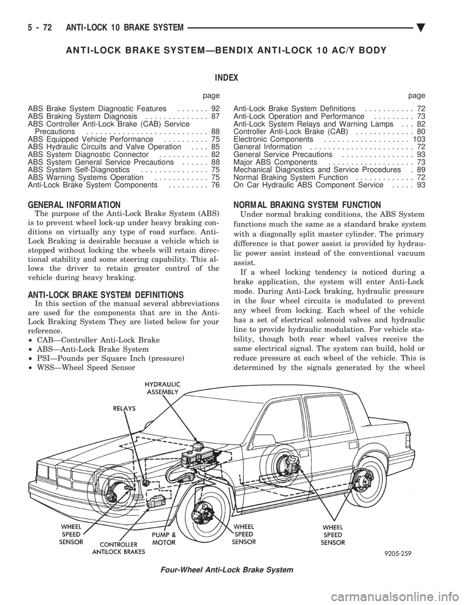
Four-Wheel Anti-Lock Brake System
5 - 72 ANTI-LOCK 10 BRAKE SYSTEM Ä
Page 223 of 2438

speed sensors (WSS) at each wheel and received at
the Controller-Anti-Lock Brake (CAB).
MAJOR ABS COMPONENTS
The following is a list of major system components.
Details of all components can be found later in this
section.
HYDRAULIC ASSEMBLY
The Hydraulic Assembly (Fig. 1) provides the func-
tion of an integral master cylinder and hydraulic
booster assembly. The hydraulic assembly contains
the wheel circuit valves used for brake pressure mod-
ulation.
WHEEL SPEED SENSORS
A Wheel Speed Sensor (Fig. 2) is located at each
wheel to transmit wheel speed information to the
Controller Anti-Lock Brake (CAB).
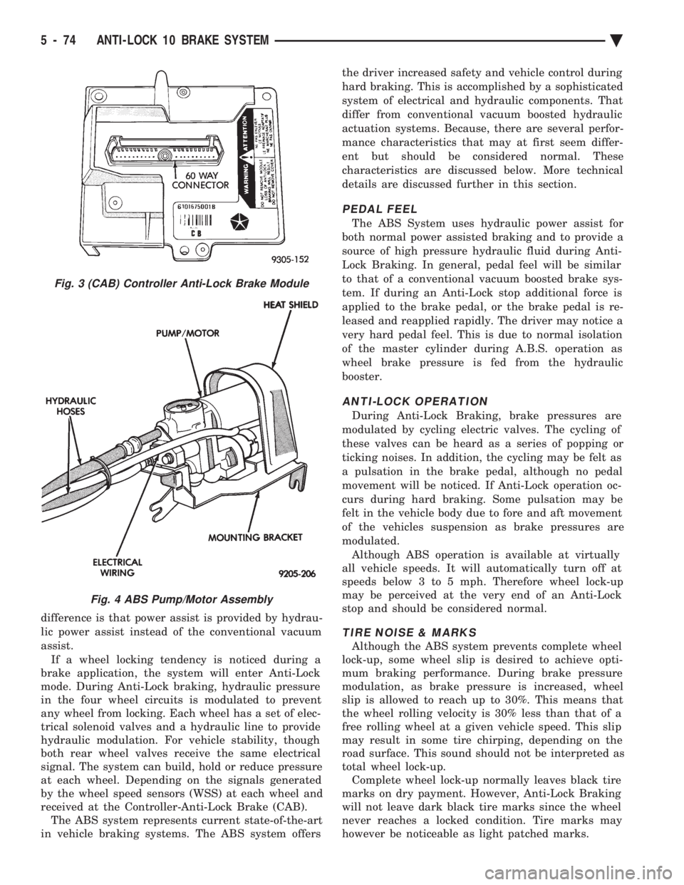
CONTROLLER-ANTI-LOCK BRAKE (CAB)
The (CAB) (Fig. 3) is a small control computer that
receives wheel speed information, controls Anti-Lock
operation and monitors system operation.
PUMP/MOTOR ASSEMBLY
The Pump/Motor Assembly (Fig. 4) is an electri-
cally driven pump. It takes low pressure brake fluid
from the hydraulic assembly reservoir and pressur- izes it for storage in the accumulators for power as-
sist and Anti -Lock braking.
ANTI-LOCK OPERATION AND PERFORMANCE
NORMAL BRAKING SYSTEM FUNCTION
Under normal braking conditions, the ABS System
functions much the same as a standard brake system
with a diagonally split master cylinder. The primary
Fig. 1 ABS Hydraulic Assembly
Fig. 2 Wheel Speed Sensor
Ä ANTI-LOCK 10 BRAKE SYSTEM 5 - 73
Page 224 of 2438

difference is that power assist is provided by hydrau-
lic power assist instead of the conventional vacuum
assist. If a wheel locking tendency is noticed during a
brake application, the system will enter Anti-Lock
mode. During Anti-Lock braking, hydraulic pressure
in the four wheel circuits is modulated to prevent
any wheel from locking. Each wheel has a set of elec-
trical solenoid valves and a hydraulic line to provide
hydraulic modulation. For vehicle stability, though
both rear wheel valves receive the same electrical
signal. The system can build, hold or reduce pressure
at each wheel. Depending on the signals generated
by the wheel speed sensors (WSS) at each wheel and
received at the Controller-Anti-Lock Brake (CAB). The ABS system represents current state-of-the-art
in vehicle braking systems. The ABS system offers the driver increased safety and vehicle control during
hard braking. This is accomplished by a sophisticated
system of electrical and hydraulic components. That
differ from conventional vacuum boosted hydraulic
actuation systems. Because, there are several perfor-
mance characteristics that may at first seem differ-
ent but should be considered normal. These
characteristics are discussed below. More technical
details are discussed further in this section.
PEDAL FEEL
The ABS System uses hydraulic power assist for
both normal power assisted braking and to provide a
source of high pressure hydraulic fluid during Anti-
Lock Braking. In general, pedal feel will be similar
to that of a conventional vacuum boosted brake sys-
tem. If during an Anti-Lock stop additional force is
applied to the brake pedal, or the brake pedal is re-
leased and reapplied rapidly. The driver may notice a
very hard pedal feel. This is due to normal isolation
of the master cylinder during A.B.S. operation as
wheel brake pressure is fed from the hydraulic
booster.
ANTI-LOCK OPERATION
During Anti-Lock Braking, brake pressures are
modulated by cycling electric valves. The cycling of
these valves can be heard as a series of popping or
ticking noises. In addition, the cycling may be felt as
a pulsation in the brake pedal, although no pedal
movement will be noticed. If Anti-Lock operation oc-
curs during hard braking. Some pulsation may be
felt in the vehicle body due to fore and aft movement
of the vehicles suspension as brake pressures are
modulated. Although ABS operation is available at virtually
all vehicle speeds. It will automatically turn off at
speeds below 3 to 5 mph. Therefore wheel lock-up
may be perceived at the very end of an Anti-Lock
stop and should be considered normal.
TIRE NOISE & MARKS
Although the ABS system prevents complete wheel
lock-up, some wheel slip is desired to achieve opti-
mum braking performance. During brake pressure
modulation, as brake pressure is increased, wheel
slip is allowed to reach up to 30%. This means that
the wheel rolling velocity is 30% less than that of a
free rolling wheel at a given vehicle speed. This slip
may result in some tire chirping, depending on the
road surface. This sound should not be interpreted as
total wheel lock-up. Complete wheel lock-up normally leaves black tire
marks on dry payment. However, Anti-Lock Braking
will not leave dark black tire marks since the wheel
never reaches a locked condition. Tire marks may
however be noticeable as light patched marks.
Fig. 3 (CAB) Controller Anti-Lock Brake Module
Fig. 4 ABS Pump/Motor Assembly
5 - 74 ANTI-LOCK 10 BRAKE SYSTEM Ä
Page 225 of 2438

ABS EQUIPPED VEHICLE PERFORMANCE
Anti-Lock Brakes provide the driver with some
steering control during hard braking. However there
are conditions where the system does not provide any
benefit. In particular, hydroplaning is still possible
when the tires ride on a film of water. Hydroplaning
results in the vehicle tires leaving the road surface
rendering the vehicle almost uncontrollable. In addi-
tion, extreme steering maneuvers at high speed or
high speed cornering beyond limits of tire adhesion
to the road surface may cause vehicle skidding. So,
the ABS system is termed Anti-Lock instead of Anti-
Skid. One of the significant benefits of the ABS system is
that of maintaining steering control during hard
braking or during braking on slippery surfaces. It is
therefore possible to steer the vehicle while braking
on almost any road surface.
ABS SYSTEM SELF-DIAGNOSTICS
The ABS system has been designed with Self Diag-
nostic Capability. There are two self checks the sys-
tems performs every time the vehicle is started.
First, when the key is turned on the system performs
an electrical check called Start-Up Cycle. During this
check, the Red Brake Warning Lamp and the Amber
Anti-Lock Warning Lamp are illuminated. Then
turned off at the end of the test, after about 1 to 2
seconds. When the vehicle reaches a speed of about 3
to 4 miles per hour. The system performs a func-
tional check called Drive-Off. During Drive-Off. hy-
draulic valves are activated briefly to test their
function. Drive-Off can be detected as a series of
rapid clicks upon driving off the first time the car is
started. If the brake pedal is applied during Drive-
Off, the test is by-passed. Both of these conditions
are a normal part of the system self test. Most fault
conditions will set a ABS Fault Code in the (CAB),
which can be retrieved to aid in fault diagnosis. De-
tails can be found in Diagnosis Section.
ABS WARNING SYSTEMS OPERATION
The ABS system uses two methods for notifying
the driver of a system malfunction. These include the
standard Red Brake Warning Lamp and an Amber
Anti-Lock Warning Lamp, both located in the instru-
ment cluster. The purpose of these two lamps are dis-
cussed in detail below.
RED BRAKE WARNING LAMP
The Red Brake Warning Lamp, located in the in-
strument cluster, will Turn On to warn the driver of
brake system conditions that may result in reduced
braking ability. The lamp is also turned on when the
parking brake is not fully released. Conditions which
may cause the Red Brake Warning Lamp to Turn On
include: ²
Parking brake not fully released. If the parking
brake is applied or not fully released. The switch on the
parking brake pedal assembly will ground the Red
Brake Warning Lamp circuit and cause the lamp to
turn on. On vehicles equipped with mechanical instru-
ment clusters, the Amber Anti-Lock Lamp will turn on
if the vehicle is driven above 3 miles per hour with the
Parking Brake applied.
² Low brake fluid. The fluid level sensor in the hy-
draulic assembly reservoir will ground the Red Brake
Warning Lamp circuit if low brake fluid level is de-
tected. In addition, ABS will be deactivated above 3
miles per hour and the Amber Anti-Lock Warning
Lamp will be illuminated. If the vehicle is equipped
with EVIC, a low fluid condition will also cause the
Low Brake Fluid message to appear.
² Low Accumulator Pressure. In the event of low
accumulator pressure, the dual function pressure
switch in the hydraulic assembly will signal the (CAB)
to ground the Red Brake Warning Lamp circuit. This
will cause the Red Brake Warning Lamp to turn on.
Low accumulator pressure also results in the activa-
tion of the Yellow Anti-Lock Warning Lamp. Low accu-
mulator pressure may result in loss of power assist.
² Modulator Or (CAB) Faults. The modulator assem-
bly or (CAB) may turn on the Yellow Anti-Lock Warn-
ing Lamp, if certain faults are detected in either the
modulator assembly or the (CAB).
² Bulb check. As a bulb check, the Red Brake Warning
Lamp will illuminate whenever the ignition switch is
placed in the crank position. Illumination of the red Brake Warning Lamp
may indicate reduced braking ability. A vehicle
that has the Red Brake Warning Lamp ON should
not be driven except to do diagnostic procedures
described in Section 2 of this manual. Most con-
ditions that turn on the Red Brake Warning
Lamp will also turn on the Amber Anti-Lock
Warning Lamp, consequently disabling the Anti-
Lock function.
ANTI-LOCK WARNING LAMP
The Anti-Lock Warning Lamp is located in the in-
strument cluster and is Amber in color. The Amber
Anti-Lock Warning Lamp is illuminated when the
(CAB) detects a condition that results in a shutdown of
Anti-Lock function. The Amber Anti-Lock Warning
Lamp is normally on until the (CAB) completes its self
tests and turns the lamp off. For example, if the (CAB)
is disconnected, the lamp is on. Display of the Amber Anti-Lock Warning Lamp
without the Red Brake Warning Lamp indicates
only that Anti-Lock function has been disabled.
Power assisted normal braking is unaffected.
Ä ANTI-LOCK 10 BRAKE SYSTEM 5 - 75
Page 229 of 2438

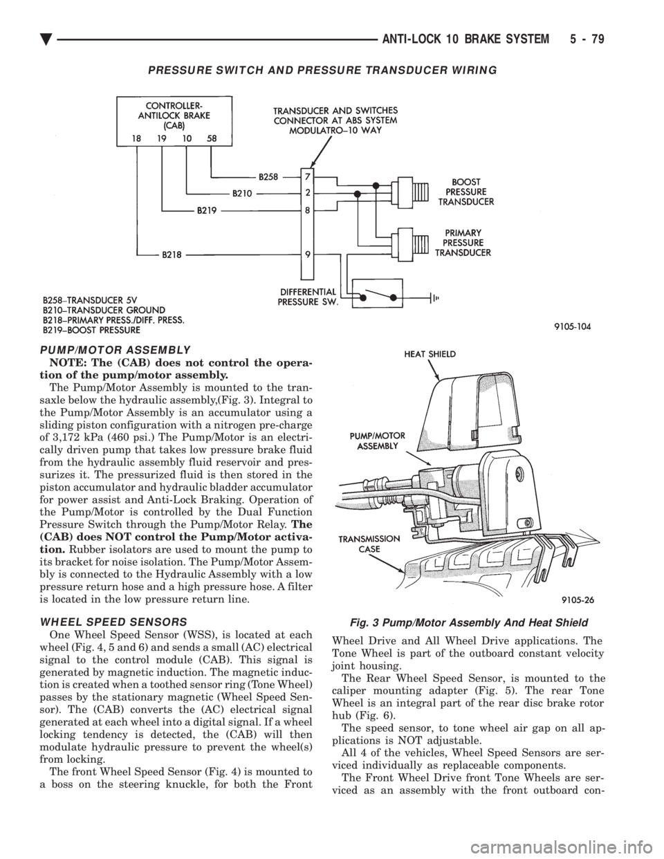
PUMP/MOTOR ASSEMBLY
NOTE: The (CAB) does not control the opera-
tion of the pump/motor assembly. The Pump/Motor Assembly is mounted to the tran-
saxle below the hydraulic assembly,(Fig. 3). Integral to
the Pump/Motor Assembly is an accumulator using a
sliding piston configuration with a nitrogen pre-charge
of 3,172 kPa (460 psi.) The Pump/Motor is an electri-
cally driven pump that takes low pressure brake fluid
from the hydraulic assembly fluid reservoir and pres-
surizes it. The pressurized fluid is then stored in the
piston accumulator and hydraulic bladder accumulator
for power assist and Anti-Lock Braking. Operation of
the Pump/Motor is controlled by the Dual Function
Pressure Switch through the Pump/Motor Relay. The
(CAB) does NOT control the Pump/Motor activa-
tion. Rubber isolators are used to mount the pump to
its bracket for noise isolation. The Pump/Motor Assem-
bly is connected to the Hydraulic Assembly with a low
pressure return hose and a high pressure hose. A filter
is located in the low pressure return line.
WHEEL SPEED SENSORS
One Wheel Speed Sensor (WSS), is located at each
wheel (Fig. 4, 5 and 6) and sends a small (AC) electrical
signal to the control module (CAB). This signal is
generated by magnetic induction. The magnetic induc-
tion is created when a toothed sensor ring (Tone Wheel)
passes by the stationary magnetic (Wheel Speed Sen-
sor). The (CAB) converts the (AC) electrical signal
generated at each wheel into a digital signal. If a wheel
locking tendency is detected, the (CAB) will then
modulate hydraulic pressure to prevent the wheel(s)
from locking. The front Wheel Speed Sensor (Fig. 4) is mounted to
a boss on the steering knuckle, for both the Front Wheel Drive and All Wheel Drive applications. The
Tone Wheel is part of the outboard constant velocity
joint housing. The Rear Wheel Speed Sensor, is mounted to the
caliper mounting adapter (Fig. 5). The rear Tone
Wheel is an integral part of the rear disc brake rotor
hub (Fig. 6). The speed sensor, to tone wheel air gap on all ap-
plications is NOT adjustable. All 4 of the vehicles, Wheel Speed Sensors are ser-
viced individually as replaceable components. The Front Wheel Drive front Tone Wheels are ser-
viced as an assembly with the front outboard con-
Fig. 3 Pump/Motor Assembly And Heat Shield
PRESSURE SWITCH AND PRESSURE TRANSDUCER WIRING
Ä ANTI-LOCK 10 BRAKE SYSTEM 5 - 79
Page 230 of 2438

stant velocity joint housings. The rear Tone Wheels
are serviced as an assembly with the rear disc brake
rotor hub. Correct Anti-Lock System operation is dependent
on wheel speed signals from the wheel speed sensors.
The vehicles' wheels and tires must all be the same
size and type to generate accurate signals. In addi-
tion, the tires must be inflated to the recommended
pressures for optimum system operation. Variations
in wheel and tire size or significant variations in in-
flation pressure can produce inaccurate wheel speed
signals.
CONTROLLER ANTI-LOCK BRAKE (CAB)
The Anti-Lock Brake Controller is a small micro-
processor based device that monitors the brake sys- tem and controls the system while it functions in
Anti-Lock Mode. The CAB is located under the bat-
tery tray and is mounted to the left frame rail (Fig.
7) and uses a 60-way system connector. The power
source for the CAB is through the ignition switch to
pin 60 of the controller. With the ignition in the
RUN or ON position. IF THE (ABS) CONTROL-
LER NEEDS TO BE REPLACED BE SURE THE
CORRECT CONTROLLER IS USED. THE CON-
TROLLER ANTI-LOCK BRAKE (CAB) IS NOT
ON THE CCD BUS
Fig. 5 Rear Wheel Speed Sensor
Fig. 4 Front Wheel Speed Sensor
Fig. 6 Rear Tone Wheel
Fig. 7 Location Controller Anti-Lock Brake (CAB)
5 - 80 ANTI-LOCK 10 BRAKE SYSTEM Ä
Page 232 of 2438

The primary functions of the (CAB) are:
² (1) Detect wheel locking tendencies.
² (2) Control fluid modulation to the brakes while in
Anti-Lock mode.
² (3) Monitor the system for proper operation.
² (4) Provide communication to the DRB II while in
diagnostic mode. The (CAB) continuously monitors the speed of each
wheel, through the signals generated at the Wheel
Speed Sensors, to determine if any wheel is begin-
ning to lock. When a wheel locking tendency is de-
tected, the (CAB) will isolate the master cylinder
from the wheel brakes. This is done by activating the
Isolation Valves. The (CAB) then commands the ap-
propriate Build or Decay valves to modulate brake
fluid pressure in some or all of the hydraulic circuits.
The fluid used for modulation comes from the booster
servo circuit. The (CAB) continues to control pres-
sure in individual hydraulic circuits until a locking
tendency is no longer present. The (ABS) system is constantly monitored by the
(CAB) for proper operation. If the (CAB) detects a
fault, it can disable the Anti-Lock braking function.
Depending on the fault, the (CAB) will light one or
both of the brake warning lamps. The (CAB) contains a System Diagnostic Program
which triggers the brake system warning lamps
when a system fault is detected. Faults are stored in
a diagnostic program memory. There are 19 fault
codes that may be stored in the (CAB) and displayed
through the DRB II. These fault codes will remain in
the (CAB) memory even after the ignition has been
turned off. These fault codes will remain in memory
until they are cleared with the DRB II, or automati-
cally erased from the memory after (50) ignition
switch on/off cycles.
CONTROLLER ANTI-LOCK BRAKE (INPUTS)
² Four wheel speed sensors.
² Boost pressure transducer.
² Primary pressure transducer.
² Low fluid level switch.
² Differential pressure switch.
² Parking brake switch.
² Dual function pressure switch (warning pressure
only)
² Stop lamp switch.
² Ignition switch.
² System relay voltage.
² Ground.
² Low Accumulator
CONTROLLER ANTI-LOCK BRAKE (OUTPUTS)
²Ten modulator valves-3 decay, 3 build and 4 isola-
tion.
² Red Brake warning lamp.
² Amber Anti-Lock Warning Lamp.
² System relay actuation. ²
Diagnostic communication.
ABS SYSTEM DIAGNOSTIC CONNECTOR
The Bendix Anti-Lock system diagnostic connector
is located under the lower dash panel or in the area
of the fuse box (Fig. 8). The fuse box is located be-
hind the access panel that is on the bottom portion of
the dash panel, left of the steering column. The diag-
nostics connector is a blue 6 way connector.
ANTI-LOCK SYSTEM RELAYS AND WARNING
LAMPS
PUMP/MOTOR RELAY
Pump/Motor power is supplied by the Pump/Motor
Relay. The Pump/Motor relay is located inside the
Power Distribution Center (PDC). The relay coil is
energized by a ground from the Dual Function Pres-
sure Switch. See (Fig. 9) for the location of the pump/
motor relay in the (PDC).
SYSTEM RELAY
The (ABS) Modulator Valves and Anti-Lock Warn-
ing Lamp Relay are controlled through a System Re-
lay. The System relay is located on the top left inner
fender behind the headlight (Fig. 10). The system re-
lay provides power to the (CAB) for modulator valve
operation (pins 47 and 50) after the start-up cycle
when the ignition is turned on.
ANTI-LOCK WARNING LAMP RELAY
The Anti-Lock Warning Lamp is controlled by the
Yellow Light Relay. See (Fig. 10) for location behind
the left headlight. With the relay de-energized, the
lamp is lit. When the system relay is energized by
Fig. 8 A.B.S. Diagnostic Connector Location
5 - 82 ANTI-LOCK 10 BRAKE SYSTEM Ä
Page 236 of 2438

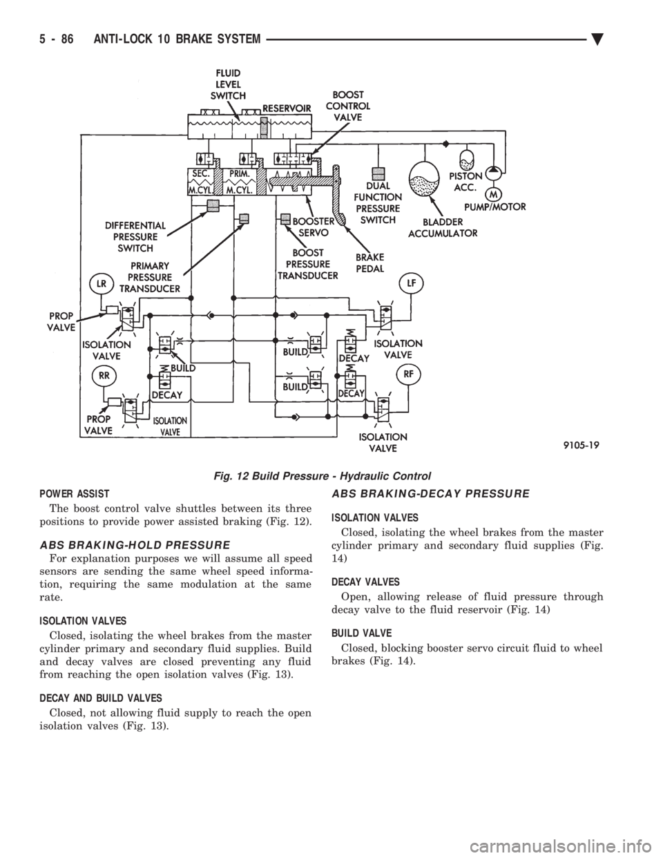
POWER ASSIST The boost control valve shuttles between its three
positions to provide power assisted braking (Fig. 12).
ABS BRAKING-HOLD PRESSURE
For explanation purposes we will assume all speed
sensors are sending the same wheel speed informa-
tion, requiring the same modulation at the same
rate.
ISOLATION VALVES Closed, isolating the wheel brakes from the master
cylinder primary and secondary fluid supplies. Build
and decay valves are closed preventing any fluid
from reaching the open isolation valves (Fig. 13).
DECAY AND BUILD VALVES Closed, not allowing fluid supply to reach the open
isolation valves (Fig. 13).
ABS BRAKING-DECAY PRESSURE
ISOLATION VALVES
Closed, isolating the wheel brakes from the master
cylinder primary and secondary fluid supplies (Fig.
14)
DECAY VALVES Open, allowing release of fluid pressure through
decay valve to the fluid reservoir (Fig. 14)
BUILD VALVE Closed, blocking booster servo circuit fluid to wheel
brakes (Fig. 14).
Fig. 12 Build Pressure - Hydraulic Control
5 - 86 ANTI-LOCK 10 BRAKE SYSTEM Ä