1993 CHEVROLET PLYMOUTH ACCLAIM brake sensor
[x] Cancel search: brake sensorPage 2 of 2438

WIRING DIAGRAMS AA-BODY
INDEX
Wiring Diagram Name Sheet Number
Anti-Lock Brake System.................41, 42, 43, 44
ABS Pump Motor Relay.......................41
ABS System Relay..........................43
Brake Switch..............................44
Controller.....................41, 42, 43, 44, 114
Data Link Connector.........................44Wiring Diagram Name Sheet Number
Diode-Warning Lamp.........................43
Hydraulic Modulator.........................41
Ignition Switch.............................44
Park Brake Switch...........................44
Wheel Sensors.............................42
ÄWIRING DIAGRAMS AA-BODY 8W - 1
Page 9 of 2438

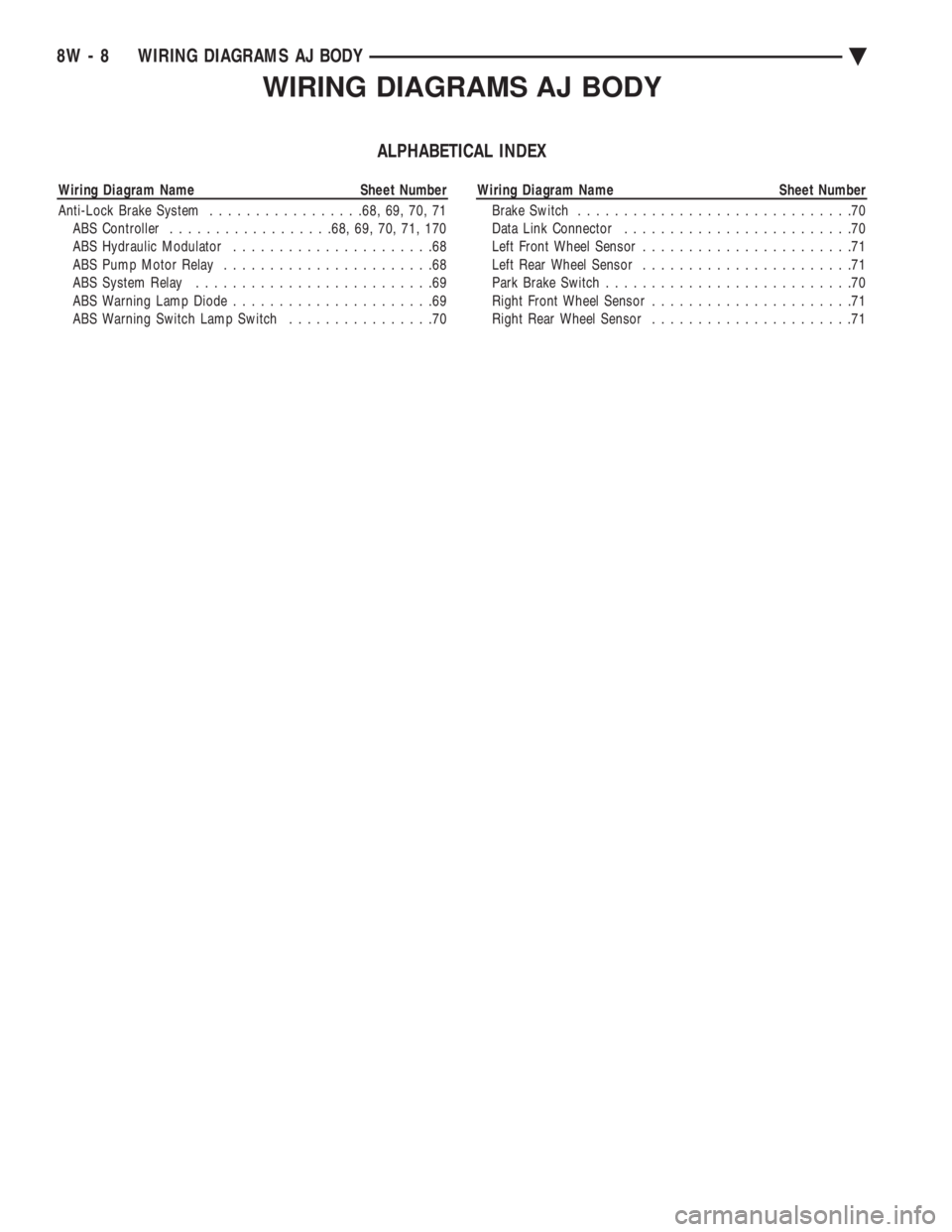
WIRING DIAGRAMS AJ BODY
ALPHABETICAL INDEX
Wiring Diagram Name Sheet Number
Anti-Lock Brake System.................68, 69, 70, 71
ABS Controller..................68, 69, 70, 71, 170
ABS Hydraulic Modulator......................68
ABS Pump Motor Relay.......................68
ABS System Relay..........................69
ABS Warning Lamp Diode......................69
ABS Warning Switch Lamp Switch................70Wiring Diagram Name Sheet Number
Brake Switch..............................70
Data Link Connector.........................70
Left Front Wheel Sensor.......................71
Left Rear Wheel Sensor.......................71
Park Brake Switch...........................70
Right Front Wheel Sensor......................71
Right Rear Wheel Sensor......................71
8W - 8 WIRING DIAGRAMS AJ BODYÄ
Page 35 of 2438

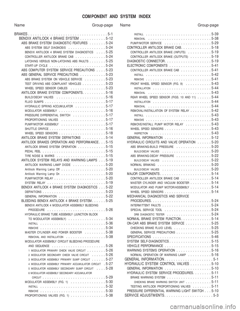
COMPONENT AND SYSTEM INDEX
Name Group-page Name Group-page
BRAKES ..................................5-1
BENDIX ANTILOCK 4 BRAKE SYSTEM ...........5-12
ABS BRAKE SYSTEM DIAGNOSTIC FEATURES.......5-24
ABS SYSTEM SELF DIAGNOSIS................ 5-24
BENDIX ANTILOCK 4 BRAKE SYSTEM DIAGNOSTICS....5-25
CONTROLLER ANTILOCK BRAKE CAB............. 5-24
LATCHING VERSUS NON-LATCHING ABS FAULTS.......5-25
START-UP CYCLE........................ 5-24
ABS COMPUTER SYSTEM SERVICE PRECAUTIONS....5-23
ABS GENERAL SERVICE PRECAUTIONS........... 5-23
ABS BRAKE SYSTEM ON VEHICLE SERVICE.........5-23
TEST DRIVING ABS COMPLAINT VEHICLES.......... 5-23
WHEEL SPEED SENSOR CABLES............... 5-23
ANTILOCK BRAKE SYSTEM COMPONENTS..........5-16
BUILD/DECAY VALVES..................... 5-16
FLUID SUMPS.......................... 5-17
HYDRAULIC SPRING ACCUMULATOR.............5-17
MODULATOR ASSEMBLY.................... 5-16
PRESSURE DIFFERENTIAL SWITCH..............5-17
PROPORTIONING VALVES................... 5-17
PUMP/MOTOR ASSEMBLY...................5-17
SHUTTLE ORIFICE........................ 5-16
WHEEL SPEED SENSORS....................5-18
ANTILOCK BRAKE SYSTEM DEFINITIONS..........5-14
ANTILOCK BRAKES OPERATION AND PERFORMANCE. . . 5-15
ANTILOCK BRAKE SYSTEM OPERATION............ 5-15
PEDAL FEEL........................... 5-15
TIRE NOISE & MARKS.....................5-15
ANTILOCK SYSTEM RELAYS AND WARNING LAMPS. . . 5-19
ANTILOCK WARNING LAMP DIODE..............5-20
Antilock Warning Lamp Off................... 5-20
Antilock Warning Lamp On...................5-20
PUMP/MOTOR RELAY...................... 5-20
SYSTEM RELAY......................... 5-19
BENDIX ANTILOCK 4 BRAKE SYSTEM DIAGNOSTICS. . . 5-22
DEFINITIONS........................... 5-23
GENERAL INFORMATION....................5-22
BLEEDING BENDIX ANTILOCK 4 BRAKE SYSTEM......5-25
BENDIX ANTILOCK 4 MODULATOR ASSEMBLY BLEEDING
PROCEDURE
......................... 5-26
HYDRAULIC BRAKE TUBE ASSEMBLY (JUNCTION BLOCK
TO MODULATOR ASSEMBLY)
................ 5-34
INSTALL............................ 5-36
REMOVE............................5-34
MASTER CYLINDER AND POWER BOOSTER.........5-38
REMOVAL AND INSTALLATION................. 5-38
MODULATOR ASSEMBLY CIRCUIT BLEEDING PROCEDURE
AND SEQUENCE
....................... 5-26
1 MODULATOR PRIMARY CHECK VALVE CIRCUIT........5-26
2 MODULATOR SECONDARY CHECK VALVE CIRCUIT......5-26
3 MODULATOR ASSEMBLY PRIMARY SUMP CIRCUIT......5-27
4 MODULATOR ASSEMBLY PRIMARY ACCUMULATOR CIRCUIT. 5-27
5 MODULATOR ASSEMBLY SECONDARY SUMP CIRCUIT....5-28
6 MODULATOR ASSEMBLY SECONDARY ACCUMULATOR
CIRCUIT
........................... 5-29
MODULATOR ASSEMBLY (FIG. 1)...............5-30
INSTALL............................ 5-32
REMOVE............................5-30
PROPORTIONING VALVES (FIG. 1)...............5-38
INSTALL............................ 5-39
REMOVAL...........................5-38
PUMP/MOTOR SERVICE....................5-29
CONTROLLER ANTILOCK BRAKE CAB.............5-18
CONTROLLER ANTILOCK BRAKE (INPUTS)..........5-19
CONTROLLER ANTILOCK BRAKE (OUTPUTS).........5-19
DIAGNOSTIC CONNECTOR.................... 5-19
ELECTRONIC COMPONENTS..................5-41
CONTROLLER ANTILOCK BRAKE CAB.............5-41
INSTALL............................ 5-42
REMOVE............................5-41
FRONT WHEEL SPEED SENSOR (FIG. 9)...........5-43
INSTALLATION......................... 5-44
REMOVAL........................... 5-43
REAR WHEEL SPEED SENSOR (FIGS. 10 AND 11)......5-44
INSTALLATION......................... 5-44
REMOVAL........................... 5-44
REMOVAL/INSTALLATION OF SYSTEM RELAY.........5-42
INSTALL............................ 5-43
REMOVE............................5-43
REMOVE/INSTALL PUMP MOTOR RELAY...........5-43
WHEEL SPEED SENSORS.................... 5-43
INSPECTION.......................... 5-43
GENERAL INFORMATION....................5-12
HYDRAULIC CIRCUITS AND VALVE OPERATION......5-20
ABS BRAKING-BUILD PRESSURE............... 5-20
BUILD/DECAY VALVES..................... 5-20
ABS BRAKING-DECAY PRESSURE...............5-22
BUILD/DECAY VALVES..................... 5-22
NORMAL BRAKING....................... 5-20
BUILD/DECAY VALVES.....................5-20
MAJOR COMPONENTS...................... 5-14
CONTROLLER ANTILOCK BRAKE CAB.............5-14
MASTER CYLINDER AND VACUUM BOOSTER.........5-14
MODULATOR AND PUMP MOTOR/ASSEMBLY.........5-14
WHEEL SPEED SENSORS.................... 5-14
MECHANICAL DIAGNOSTICS AND SERVICE
PROCEDURES
.......................... 5-24
INTERMITTENT FAULTS.....................5-24
SPECIAL SERVICE TOOL....................5-24
DRB DIAGNOSTIC TESTER...................5-24
NORMAL BRAKE SYSTEM FUNCTION.............5-14
ON-CAR ABS BRAKE SYSTEM SERVICE...........5-25
CHECKING BRAKE FLUID LEVEL................ 5-25
GENERAL SERVICE PRECAUTIONS...............5-25
SPECIFICATIONS......................... 5-46
SYSTEM SELF-DIAGNOSTICS..................5-15
VEHICLE PERFORMANCE.................... 5-15
WARNING SYSTEMS OPERATION...............5-16
NORMAL OPERATION OF WARNING LAMP..........5-16
GENERAL INFORMATION .....................5-1
HYDRAULIC SYSTEM CONTROL VALVES .........5-10
GENERAL INFORMATION.................... 5-10
HYDRAULIC SYSTEM SERVICE PROCEDURES........5-11
BRAKE WARNING SYSTEM................... 5-11
CHECKING BRAKE WARNING SWITCH UNIT...........5-11
TESTING ANTILOCK PROPORTIONING VALVES........5-11
PRESSURE DIFFERENTIAL WARNING LIGHT SWITCH. . . 5-10
SERVICE ADJUSTMENTS .....................5-3
Page 132 of 2438

FRONT AND REAR AIR SPRINGS
The front and rear air springs are essentially pneu-
matic cylinders that replace the steel coil springs.
The air filled springs allow the vehicle suspension
height to be adjusted for all weight conditions. The air springs allow for the reduction of spring
rates to improve vehicle ride characteristics.
FRONT/REAR SPRING SOLENOIDS
The front and rear solenoids control air flow in and
out of the front and rear springs. The Air Suspension
Control Module (ASCM) opens the solenoids when
the system requires air to be added to or exhausted
from the air springs. The solenoids operate at a cur-
rent draw range of 0.6 to 1.5 amps.
HEIGHT SENSOR
A magnetic switch type sensor. Located in the
right rear shock absorber and left and right front
struts, (Fig. 2) monitors vehicle height. The sensors
transmit signals to the (ASCM) relating to vehicle
height status (low, trim, medium, high).
CONTROL MODULE
The Air Suspension Control Module (ASCM). Is a
device that controls the ground circuits for the Com-
pressor Relay, Compressor Exhaust Solenoid Valve
and Front and Rear Solenoid Valves. The (ASCM)
limits the compressor pump operation time to 170 to
190 seconds. This controlled operation time is to pre- vent damage to the compressor motor.
To prevent excessive cycling between the compres-
sor and the exhaust solenoid circuits during normal
ride conditions. A 14 to 16 second delay is incorpo-
rated in the microprocessor logic. The system is non-operation when one of the fol-
lowing conditions exists. A door(s) is/are open, the
trunk is open, the service brake is applied or the
throttle position sensor is 65% to 100% open. System
operation is inhibited during high speed cornering
activities or if there is a charging system failure.
The control module is on the CCD bus system.
COMPRESSOR ASSEMBLY
The compressor assembly is driven by an electric
motor and supplies air pressure between 930 to 1241
kPa (135 to 180 psi) (Fig. 3). A solenoid operated ex-
haust valve. Located in the compressor head assem-
bly, releases air when energized. A heat actuated circuit breaker. Located inside the
compressor motor housing. Is used to prevent damage
to the compressor motor in case of control module
failure.
COMPRESSOR AIR DRYER
The air dryer is attached to the compressor (Fig. 3).
This component serves two purposes. It absorbs mois-
ture from the atmosphere before it enters the system
Fig. 2 Front and Rear Air Springs
2 - 74 SUSPENSION AND DRIVESHAFTS Ä
Page 151 of 2438

BRAKES
CONTENTS
page page
ANTI-LOCK BRAKE SYSTEMÐBENDIX ANTI-LOCK 10 AC/Y BODY ............. 72
ANTI-LOCK BRAKE SYSTEMÐBENDIX ANTI-LOCK 6 AA,AG,AJ,AP BODY ....... 113
BRAKE DISC (ROTOR) ................... 53
BRAKE SUPPORT ASSEMBLY ............. 25
FRONT DISC BRAKES ................... 31
GENERAL INFORMATION .................. 1
HYDRAULIC SYSTEM CONTROL VALVES . . . 26
KELSEY HAYES DOUBLE PIN FAMILY CALIPER ............................ 35 KELSEY HAYES DOUBLE PIN NON-FAMILY
CALIPER ............................ 38
MASTER CYLINDER ..................... 66
PARKING BRAKES ...................... 57
POWER BRAKES ....................... 68
REAR DISC BRAKES .................... 45
REAR WHEEL DRUM BRAKES ............ 18
SERVICE ADJUSTMENTS .................. 4
WHEEL BEARINGS ...................... 70
WHEEL CYLINDERS ..................... 23
GENERAL INFORMATION
Throughout this group, references may be made to
a particular vehicle by letter or number designation.
A chart showing the break down of these designa-
tions is included in the Introduction Section at the
front of this service manual. Standard brake equipment consists of:
² Double pin floating caliper disc front brakes.
² Rear automatic adjusting drum brakes.
² Differential valve with a brake warning switch.
² Master cylinder.
² Vacuum power booster.
² Double pin floating caliper rear disc brakes are
available on some models. The Bendix Anti-Lock 10 braking system, uses the
standard power brake system caliper assemblies,
braking discs, pedal assembly, brake lines and hoses.
The unique parts of the Bendix Anti-Lock 10 braking
system consists of the following components. Propor-
tioning valves, wheel speed sensors, tone wheels,
electronic control unit, modulator assembly and hy-
draulic assembly. These components replace the con-
ventional master cylinder and power booster. The
components will be described in detail in the Bendix
Anti-Lock 10 brake section in this group of the ser-
vice manual. The Bendix Anti-Lock 6 braking system, uses the
following standard brake system components. Master
cylinder, power booster, caliper assemblies, braking
discs, pedal assembly, brake lines and hoses. The
unique parts of the Bendix Anti-Lock 6 braking sys-
tem consists of the following components. Modulator
assembly, unique proportioning valves, wheel speed
sensors, tone wheels, and electronic control unit.
These components will be described in detail in the
Bendix Anti-Lock 6 brake section in this group of the
service manual. The front disc brake shoes have semi-metallic lin-
ings. The hydraulic brake system (Fig .123and4)is
diagonally split on both the Non-ABS and ABS brak-
ing system. With the left front and right rear brakes
on one hydraulic system and the right front and left
rear on the other. The Non-ABS and ABS brake system may use dif-
ferent types of brake line fittings and tubing flares.
The Non-ABS brake system uses double wall tubing
flares and fittings at all tubing joint locations. Some
ABS brake systems use both ISO style tubing flares
and double wall tubing flares and corresponding fit-
tings at different joint locations. See (Figs . 2 3 and 4)
for specific joint locations and type of tubing flare. The front disc brakes consist of two different types
of caliper assemblies. A double pin Kelsey-Hayes cal-
iper (family caliper) with a bolt-on adapter attached
to the steering knuckle. Or a double pin Kelsey-
Hayes caliper (non-family caliper) which mounts di-
rectly to rails on the steering knuckle. The non-
family caliper is only used on the AY Body
(Imperials).
CAUTION: Caliper pistons, boots and seals for the
different caliper assemblies used on the front and
rear disc brake assemblies are not interchangeable.
Misusage could result in a complete brake system
failure. Be sure that the parts are replaced with the
correct replacement parts, refer to the parts book
for the type and model year of the vehicle being
worked on.
The master cylinder is anodized, lightweight alu-
minum, with a bore size of 24.0mm, 21.0mm or 7/8
inch.
Ä BRAKES 5 - 1
Page 182 of 2438

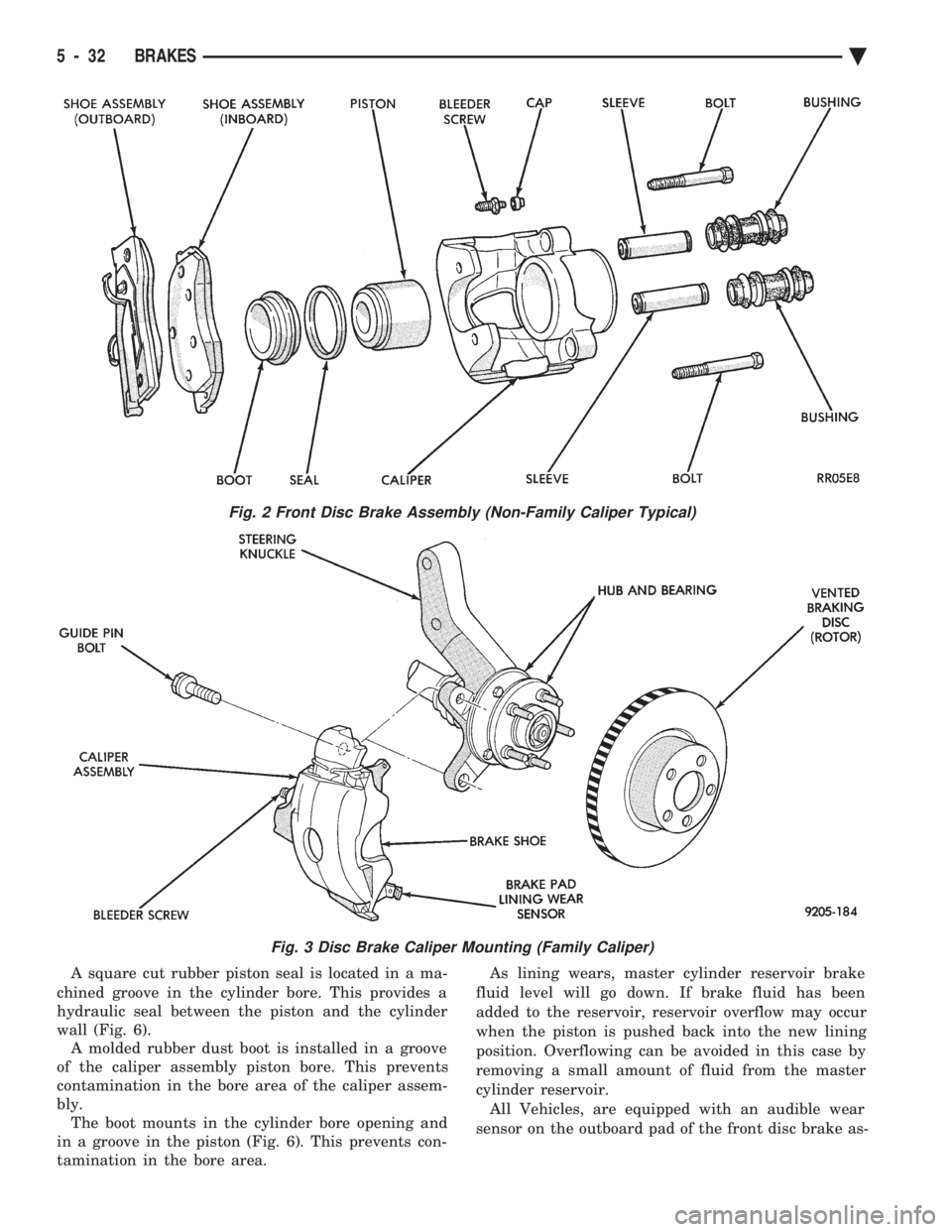
A square cut rubber piston seal is located in a ma-
chined groove in the cylinder bore. This provides a
hydraulic seal between the piston and the cylinder
wall (Fig. 6). A molded rubber dust boot is installed in a groove
of the caliper assembly piston bore. This prevents
contamination in the bore area of the caliper assem-
bly. The boot mounts in the cylinder bore opening and
in a groove in the piston (Fig. 6). This prevents con-
tamination in the bore area. As lining wears, master cylinder reservoir brake
fluid level will go down. If brake fluid has been
added to the reservoir, reservoir overflow may occur
when the piston is pushed back into the new lining
position. Overflowing can be avoided in this case by
removing a small amount of fluid from the master
cylinder reservoir. All Vehicles, are equipped with an audible wear
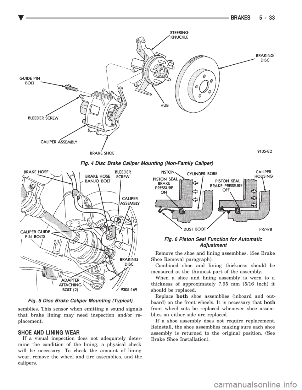
sensor on the outboard pad of the front disc brake as-
Fig. 2 Front Disc Brake Assembly (Non-Family Caliper Typical)
Fig. 3 Disc Brake Caliper Mounting (Family Caliper)
5 - 32 BRAKES Ä
Page 183 of 2438

semblies. This sensor when emitting a sound signals
that brake lining may need inspection and/or re-
placement.
SHOE AND LINING WEAR
If a visual inspection does not adequately deter-
mine the condition of the lining, a physical check
will be necessary. To check the amount of lining
wear, remove the wheel and tire assemblies, and the
calipers. Remove the shoe and lining assemblies. (See Brake
Shoe Removal paragraph). Combined shoe and lining thickness should be
measured at the thinnest part of the assembly. When a shoe and lining assembly is worn to a
thickness of approximately 7.95 mm (5/16 inch) it
should be replaced. Replace bothshoe assemblies (inboard and out-
board) on the front wheels. It is necessary that both
front wheel sets be replaced whenever shoe assem-
blies on either side are replaced. If a shoe assembly does not require replacement.
Reinstall, the shoe assemblies making sure each shoe
assembly is returned to the original position. (See
Brake Shoe Installation).
Fig. 4 Disc Brake Caliper Mounting (Non-Family Caliper)
Fig. 5 Disc Brake Caliper Mounting (Typical)
Fig. 6 Piston Seal Function for Automatic Adjustment
Ä BRAKES 5 - 33
Page 216 of 2438

MASTER CYLINDER INDEX
page page
Brake Fluid Level Sensor .................. 66
General Information ....................... 66 Master Cylinder Service Procedures
.......... 67
Testing the Master Cylinder ................. 66
GENERAL INFORMATION
The tandem master cylinder (Fig. 1) has a glass re-
inforced nylon reservoir and an anodized aluminum
body. Do not hone the bore of the cylinder, as this will
remove the anodized surface. The reservoir is indexed to prevent installation in
the wrong direction (Fig. 2). The cap diaphragms are
slit to allow atmospheric pressure to equalize on both
sides of the diaphragm. The primary and secondary outlet tubes from the
master cylinder are connected to the valve mounted
under the master cylinder. The front part of this
block connects to the secondary outlet tube and sup-
plies the right rear and left front brakes. The rear
portion of the block connects to the primary outlet
tube and supplies the right front and left rear
brakes.
BRAKE FLUID LEVEL SENSOR
The Brake Fluid Level sensor is found only in the
AJ body vehicles with the visual electronic message
center. The purpose of the sensor is to provide the
driver with an early warning message that brake
fluid in master cylinder reservoir has dropped to a
below normal. As the fluid drops below the design level the sensor
closes the warning message circuit. Approximately
15 seconds later the message BRAKE FLUID LOW
appears on the instrument panel. At this time the master cylinder reservoir should be checked and filled
to the bottom of the rings with DOT 3 brake fluid. To check the operation of the Brake Fluid Level
sensor, with ignition on and wiring still attache-
d,remove sensor from master cylinder and hold in
upright position. Within 30 seconds the instrument
panel message BRAKE FLUID LOW should appear.
Next invert the sensor. The instrument panel message
should turn off immediately. If the above sequence
occurs the sensor is operating properly. If the message
does not appear remove the wiring from the sensor and
using a jumper wire connect both sides of the plug. The
instrumental panel message BRAKE FLUID LOW
should appear within 30 seconds. If the message does
not appear a problem exists in the wiring or instru-
mentation. If the message does appear the sensor is
faulty and must be replaced. The Brake Fluid Level
sensor is not a repairable item (Fig. 2).
TESTING THE MASTER CYLINDER
Be sure master cylinder vents at both ports.
Apply pedal lightly with engine running and look for
fluid squirting or swirling into reservoirs. In this master cylinder, a special baffle reduces the
amount of fluid entering the secondary reservoir only a
small disturbance may be seen.
Fig. 1 Aluminum Master Cylinder (Cutaway View)
Fig. 2 Brake Fluid Level Sensor
5 - 66 BRAKES Ä