1993 CHEVROLET PLYMOUTH ACCLAIM ECO mode
[x] Cancel search: ECO modePage 271 of 2438

Lamp Relay opens the Anti-Lock Warning Lamp Re-
lay switch. This breaks the ground path to the Am-
ber Anti-Lock Warning Lamp and the light is turned
off. The (CAB) by itself, also has the ability to turn on
the Amber Anti-Lock Warning Lamp. The (CAB) can
turn on the Amber Anti-Lock Warning Lamp by pro-
viding a ground at pin 15.
ANTI-LOCK WARNING LAMP ON
System Relay and Anti-Lock Warning Lamp
Relay De-Energized. When the Amber Anti-Lock Warning Lamp is on,
there is no electrical current flow from the (CAB) at
pin 57. The System Relay coil is NOT energized. No
electrical current flows to pin 47 and 41 (modulator
valve power), or to the Anti-Lock Warning Lamp Re-
lay coil. Thus, the Amber Anti-Lock Warning Lamp
is not energized. The Amber Anti-Lock Warning Lamp is grounded through the Anti-Lock Warning
Lamp Relay contacts. The Amber Anti-Lock Warning
Lamp is turned on.
HYDRAULIC CIRCUITS AND VALVE OPERATION
Through the following operation descriptions and
diagrams. The function of the various hydraulic con-
trol valves in the ABS system will be described. The
fluid control valves mentioned below, control the flow
of pressurized brake fluid to the wheel brakes during
the different modes of Anti-Lock braking. For explanation purposes we will assume all speed
sensors are sending the same wheel speed informa-
tion, requiring the same hydraulic fluid modulation
at the same rate.
NORMAL BRAKING
ISOLATION VALVES
Open to primary and secondary master cylinder
fluid supply (Fig. 1)
BUILD/DECAY VALVES Closed (Fig. 1)
The brake pedal is applied. The travel of the brake
pedal closes primary and secondary circuits from the
master cylinder fluid supply. Brake fluid from the
primary and secondary circuits flows through the
open isolation valves, through the build/decay valves
to the wheel brakes.
ABS BRAKING-BUILD PRESSURE
ISOLATION VALVES
Closed, isolating wheel brakes from master cylin-
der primary and secondary fluid supply. Through
open build valves (Fig. 2).
BUILD/DECAY VALVES Open (Fig. 2)
Fig. 11 Pump Motor Relay W/O Power Distribution Center
Ä ANTI-LOCK 6 BRAKE SYSTEM 5 - 121
Page 277 of 2438
WARNING: WHEN BLEEDING THE MODULATOR
ASSEMBLY WEAR SAFETY GLASSES. A CLEAR
BLEED TUBE MUST BE ATTACHED TO THE
BLEEDER SCREWS AND SUBMERGED IN A CLEAR
CONTAINER FILLED PART WAY WITH CLEAN
BRAKE FLUID. DIRECT THE FLOW OF BRAKE
FLUID AWAY FROM THE PAINTED SURFACES OF
THE VEHICLE. BRAKE FLUID AT HIGH PRESSURE
MAY COME OUT OF THE BLEEDER SCREWS,
WHEN OPENED.
When bleeding the Modulator Assembly. The fol-
lowing bleeding sequence MUSTbe followed to in-
sure complete and adequate bleeding of the brakes
hydraulic system. The Modulator Assembly can be
bled using a Manual bleeding procedure or standard
Pressure Bleeding Equipment. If the brake system is to be bled using pressure
bleeding equipment. Refer to Bleeding Brake System,
in the Service Adjustments section at the beginning
of this group, for proper equipment usage and proce-
dures.
MODULATOR ASSEMBLY BLEEDING SEQUENCE
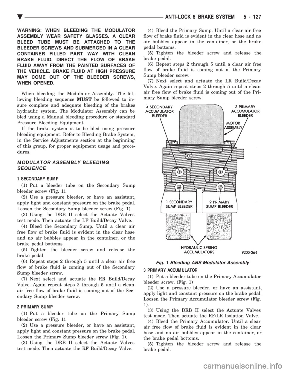
1 SECONDARY SUMP
(1) Put a bleeder tube on the Secondary Sump
bleeder screw (Fig. 1). (2) Use a pressure bleeder, or have an assistant,
apply light and constant pressure on the brake pedal.
Loosen the Secondary Sump bleeder screw (Fig. 1). (3) Using the DRB II select the Actuate Valves
test mode. Then actuate the LF Build/Decay Valve. (4) Bleed the Secondary Sump. Until a clear air
free flow of brake fluid is evident in the clear hose
and no air bubbles appear in the container, or the
brake pedal bottoms. (5) Tighten the bleeder screw and release the
brake pedal. (6) Repeat steps 2 through 5 until a clear air free
flow of brake fluid is coming out of the Secondary
Sump bleeder screw. (7) Next select and actuate the RR Build/Decay
Valve. Again repeat steps 2 through 5 until a clean
air free flow of brake fluid is coming out of the Sec-
ondary Sump bleeder screw.
2 PRIMARY SUMP
(1) Put a bleeder tube on the Primary Sump
bleeder screw (Fig. 1). (2) Use a pressure bleeder, or have an assistant,
apply light and constant pressure on the brake pedal.
Loosen the Primary Sump bleeder screw (Fig. 1). (3) Using the DRB II select the Actuate Valves
test mode. Then actuate the RF Build/Decay Valve. (4) Bleed the Primary Sump. Until a clear air free
flow of brake fluid is evident in the clear hose and no
air bubbles appear in the container, or the brake
pedal bottoms. (5) Tighten the bleeder screw and release the
brake pedal. (6) Repeat steps 2 through 5 until a clear air free
flow of brake fluid is coming out of the Primary
Sump bleeder screw. (7) Next select and actuate the LR Build/Decay
Valve. Again repeat steps 2 through 5 until a clean
air free flow of brake fluid is coming out of the Pri-
mary Sump bleeder screw.
3 PRIMARY ACCUMULATOR
(1) Put a bleeder tube on the Primary Accumulator
bleeder screw. (Fig. 1) (2) Use a pressure bleeder, or have an assistant,
apply light and constant pressure on the brake pedal.
Loosen the Primary Accumulator bleeder screw (Fig.
1). (3) Using the DRB II select the Actuate Valves
test mode. Then actuate the RF/LR Isolation Valve. (4) Bleed the Primary Accumulator. Until a clear
air free flow of brake fluid is evident in the clear
hose and no air bubbles appear in the container, or
the brake pedal bottoms. (5) Tighten the bleeder screw and release the
brake pedal.
Fig. 1 Bleeding ABS Modulator Assembly
Ä ANTI-LOCK 6 BRAKE SYSTEM 5 - 127
Page 278 of 2438
(6) Repeat steps 2 through 5 until a clear air free
flow of brake fluid is coming out of the Primary Ac-
cumulator bleeder screw. (7) Next select and actuate the RF Build/Decay
Valve. Again repeat steps 2 through 5 until a clean
air free flow of brake fluid is coming out of the Pri-
mary Accumulator bleeder screw.
4 SECONDARY ACCUMULATOR (1) Put a bleeder tube on the Secondary Accumu-
lator bleeder screw. (Fig. 1) (2) Use a pressure bleeder, or have an assistant,
apply light and constant pressure on the brake pedal.
Loosen the Secondary Accumulator bleeder screw
(Fig. 1). (3) Using the DRB II select the Actuate Valves
test mode. Then actuate the LF/RR Isolation Valve. (4) Bleed the Secondary Accumulator. Until a clear
air free flow of brake fluid is evident in the clear
hose and no air bubbles appear in the container, or
the brake pedal bottoms. (5) Tighten the bleeder screw and release the
brake pedal. (6) Repeat steps 2 through 5 until a clear air free
flow of brake fluid is coming out of the Secondary
Accumulator bleeder screw. (7) Next select and actuate the LF Build/Decay
Valve. Again repeat steps 2 through 5 until a clean
air free flow of brake fluid is coming out of the Pri-
mary Accumulator bleeder screw.PUMP/MOTOR SERVICE
On the Bendix Anti-Lock 6 Brake System the
Pump/Motor assembly can only be serviced as part of
Modulator Assembly.
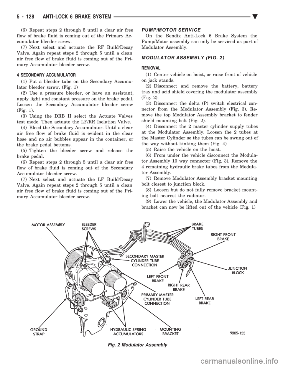
MODULATOR ASSEMBLY (FIG. 2)
REMOVAL
(1) Center vehicle on hoist, or raise front of vehicle
on jack stands. (2) Disconnect and remove the battery, battery
tray and acid shield covering the modulator assembly
(Fig. 2). (3) Disconnect the delta (P) switch electrical con-
nector from the Modulator Assembly (Fig. 3). Re-
move the top Modulator Assembly bracket to fender
shield mounting bolt (Fig. 2). (4) Disconnect the 2 master cylinder supply tubes
at the Modulator Assembly. Loosen the 2 tubes at
the Master Cylinder so the tubes can be swung out of
the way without kinking them (Fig. 4) (5) Raise the vehicle on the hoist.
(6) From under the vehicle disconnect the Modula-
tor Assembly 10 way connector (Fig. 3). Remove the
4 remaining hydraulic brake tubes from the Modula-
tor Assembly. (7) Remove Modulator Assembly bracket mounting
bolt closest to junction block. (8) Loosen but do not fully remove bracket mount-
ing bolt nearest the radiator. (9) Lower the vehicle, the Modulator Assembly and
bracket can now be lifted out of the vehicle (Fig. 1)
Fig. 2 Modulator Assembly
5 - 128 ANTI-LOCK 6 BRAKE SYSTEM Ä
Page 296 of 2438
HYDRAULIC SYSTEM CONTROL VALVES INDEX
page page
General Information ....................... 10
Hydraulic System Service Procedures ......... 11 Pressure Differential Warning Light Switch
...... 10
GENERAL INFORMATION
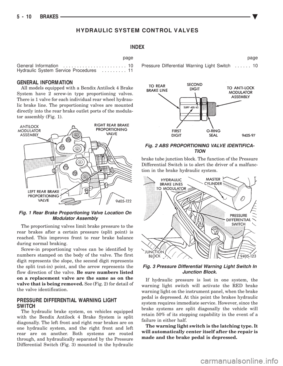
All models equipped with a Bendix Antilock 4 Brake
System have 2 screw-in type proportioning valves.
There is 1 valve for each individual rear wheel hydrau-
lic brake line. The proportioning valves are mounted
directly into the rear brake outlet ports of the modula-
tor assembly (Fig. 1).
The proportioning valves limit brake pressure to the
rear brakes after a certain pressure (split point) is
reached. This improves front to rear brake balance
during normal braking. Screw-in proportioning valves can be identified by
numbers stamped on the body of the valve. The first
digit represents the slope, the second digit represents
the split (cut-in) point, and the arrow represents the
flow direction of the valve. Be sure numbers listed
on a replacement valve are the same as on the
valve that is being removed. See (Fig. 2) for detail of
the valve identification.
PRESSURE DIFFERENTIAL WARNING LIGHT
SWITCH
The hydraulic brake system, on vehicles equipped
with the Bendix Antilock 4 Brake System is split
diagonally. The left front and right rear brakes are on
one hydraulic system, and the right front and left
rear are on another. Both systems are routed
through, and hydraulically separated by the Pressure
Differential Switch (Fig. 3) mounted in the hydraulic brake tube junction block. The function of the Pressure
Differential Switch is to alert the driver of a malfunc-
tion in the brake hydraulic system.
If hydraulic pressure is lost in one system, the
warning light switch will activate the RED brake
warning light on the instrument panel, when the brake
pedal is depressed. At this point the brakes hydraulic
system requires immediate service. However, since the
brake systems are split diagonally the vehicle will
retain 50% of its stopping capability in the event of a
failure in either half. The warning light switch is the latching type. It
will automatically center itself after the repair is
made and the brake pedal is depressed.
Fig. 1 Rear Brake Proportioning Valve Location On Modulator Assembly
Fig. 2 ABS PROPORTIONING VALVE IDENTIFICA- TION
Fig. 3 Pressure Differential Warning Light Switch InJunction Block.
5 - 10 BRAKES Ä
Page 300 of 2438

ANTILOCK BRAKE SYSTEM DEFINITIONS
In this section of the manual several abbreviations
are used for the components that are in the Bendix An-
tilock 4 Brake System, they are listed below for your
reference.
² CABÐController Antilock Brake
² ABSÐAntilock Brake System
² PSIÐPounds per Square Inch (pressure)
² WSSÐWheel Speed Sensor
² ACÐAlternating Current
NORMAL BRAKE SYSTEM FUNCTION
Under normal braking conditions, the Bendix An-
tilock 4 Brake System functions the same as a stan-
dard non-Antilock brake system.
When a wheel locking tendency is detected during a
brake application, the vehicle brake system will enter
the Antilock mode. During Antilock Braking, hydraulic
pressure in the four wheel circuits is modulated to pre-
vent wheels from locking. Each wheel circuit is de-
signed with a set of electrical valves and hydraulic line
to provide modulation, although for vehicle stability,
both rear wheel valves receive the same electrical sig-
nal. The system can modulate pressure at each wheel,
depending on signals generated by the wheel speed sen-
sors (WSS) and received at the CAB.
MAJOR COMPONENTS
The following is a list of major system components.
Details of all components can be found later in this
section. See (Fig. 1) for the general location of the
components in the vehicle.
MASTER CYLINDER AND VACUUM BOOSTER
The Bendix Antilock 4 Brake System uses a vehi-
cles standard Master Cylinder/Reservoir and Vacuum
Booster (Fig. 2). The master cylinder primary and
secondary outputs (Fig. 2) go to the frame rail
mounted junction block and then directly to the mod-
ulator assembly inlet ports.
MODULATOR AND PUMP MOTOR/ASSEMBLY
The Modulator Assembly (Fig. 3) contains the elec-
tronic valves used for brake pressure modulation,
and the Pump/Motor assembly.
The Pump/Motor function, as part of the modulator
assembly, is to pump low pressure brake fluid from the
modulator sump into the ABS accumulator, as required.
WHEEL SPEED SENSORS
A Wheel Speed Sensor (Fig. 4) is located at each
wheel to transmit wheel speed information to the CAB.
CONTROLLER ANTILOCK BRAKE CAB
The CAB (Fig. 5) is a small computer which re-
ceives wheel speed information, controls Antilock op-
eration and monitors system operation.
Fig. 2 Master Cylinder And Brake Booster Assembly
Fig. 3 Modulator And Pump/Motor Assembly
Fig. 4 Wheel Speed Sensor
5 - 14 ANTILOCK 4 BRAKE SYSTEM Ä
Page 302 of 2438

(2) The voltage output from each of the wheel
speed sensors is verified to be within the correct op-
erating range. If a vehicle is not set in motion within 3 minutes
from the time the ignition switch is turned to the on
position. The solenoid valve test is bypassed but the
pump/motor is activated briefly to verify that it is op-
erating correctly.
WARNING SYSTEMS OPERATION
The ABS system uses an Amber Antilock Warning
Lamp, located in the instrument cluster. The purpose
of the warning lamp is discussed in detail below. The Amber Antilock Warning Light will turn on
whenever the CAB detects a condition which results
in a shutdown of the Antilock brake system. The
Amber Antilock Warning Lamp is normally on until
the CAB completes its self tests and turns the lamp
off (approximately 1-2 seconds). When the Amber
Antilock Warning Light is on, only the Antilock
brake function of the brake system if affected. The
standard brake system and the ability to stop the car
will not be affected when only the Amber Antilock
Warning Light is on.
NORMAL OPERATION OF WARNING LAMP
With ignition key turned to the Crank position, the
Red Brake Warning Lamp and Amber Antilock
Warning Lamp will turn on as a bulb check. The
Amber Antilock Warning Lamp will stay on for 1-2
seconds then turn off, once verification of Antilock
Brake System self diagnosis is completed.
ANTILOCK BRAKE SYSTEM COMPONENTS
The following is a detailed description of the Ben-
dix Antilock 4 Brake System components. For infor-
mation on servicing the Four Wheel Disc Brake
System, see the standard Brake section in the Front
Wheel Drive Car, chassis service manual.
MODULATOR ASSEMBLY
WARNING: THE ONLY COMPONENTS OF THE
MODULATOR ASSSEMBLY THAT ARE SERVICE-
ABLE, ARE THE 2 PROPORTIONING VALVES,
BLEED SCREWS AND THREAD SAVERS. THE RE-
MAINING COMPONENTS OF THE MODULATOR AS-
SEMBLY ARE NOT INTENDED TO BE
SERVICEABLE ITEMS. NO ATTEMPT SHOULD BE
MADE TO REMOVE OR SERVICE ANY OTHER COM-
PONENTS OF THE MODEULATOR ASSEMBLY.
The Modulator Assembly (Fig. 1) is located under
the battery tray and is covered with an acid shield.
The Modulator Assembly contains the following com-
ponents for controlling the Antilock brake system. 4
Build/Decay Valves, 4 Shuttle Orifices, 2 Fluid
Sumps, 2 Accumulators, and a Pump/Motor assem- bly. Also attached to the Modulator Assembly are 6
brake tubes which are connected to a 12 way junc-
tion block. The junction block (Fig. 2) is mounted to
the left frame rail below the master cylinder in the
same location as the non ABS equipped combination
valve. The wheel brake lines are attached to the sys-
tem via the connector block.BUILD/DECAY VALVES
There are 4 Build/Decay valves, one for each
wheel. In the released position they provide a fluid
path direct to the wheel brakes. In the actuated (de-
cay) position, they provide a fluid path from the
wheel brakes to the sump. The Build/Decay valves
are spring loaded in the released (build) position.
SHUTTLE ORIFICE
There are 4 Shuttle Orifice Valves, one for each
wheel. The Shuttle Orifice Valve is a hydraulically
actuated valve which shuttles when the Build/Decay
valve is actuated. Actuating of the Build/Decay valve
causes a pressure differential to be created across the
Shuttle Orifice Valve. This acts like placing an ori-
Fig. 1 Modulator Assembly
Fig. 2 Antilock Brake Junction Block
5 - 16 ANTILOCK 4 BRAKE SYSTEM Ä
Page 304 of 2438

WHEEL SPEED SENSORS
One Wheel Speed Sensor (WSS), is located at each
wheel (Fig. 5 and 6), and sends a small AC signal to the
control module CAB. This signal is generated by mag-
netic induction. The magnetic induction is created,
when a toothed sensor ring (Tone Wheel) (Fig. 7) passes
a stationary magnetic Wheel Speed Sensor. The CAB
converts the AC signal generated at each wheel into a
digital signal. If a wheel locking tendency is detected,
the CAB will then modulate hydraulic pressure to pre-
vent the wheel or wheels from locking.
The front Wheel Speed Sensor is attached to a boss
in the steering knuckle (Fig. 5). The tone wheel is
part of the outboard constant velocity joint (Fig. 5). The rear Wheel Speed Sensor is mounted to the cal-
iper adapter (Fig. 6) and the rear tone wheel is an
integral part of the rear wheel hub (Fig. 7). The
speed sensor air gap is NOT adjustable.
The four Wheel Speed Sensors are serviced individ-
ually. The front Tone Wheels are serviced as an as-
sembly with the outboard constant velocity joint. The
rear Tone Wheels are serviced as an assembly with
the rear brake hub. Correct Antilock system operation is dependent on
the vehicle's wheel speed signals, that are generated
by the Wheel Speed Sensors. The vehicle's wheels
and tires must all be the same size and type to gen-
erate accurate signals. In addition, the tires must be
inflated to the recommended pressures for optimum
system operation. Variations in wheel and tire size
or significant variations in inflation pressure can
produce inaccurate wheel speed signals.
CONTROLLER ANTILOCK BRAKE CAB
The Antilock Brake Controller is a small micropro-
cessor based device which monitors the brake system
and controls the system while it functions in the An-
tilock mode. The CAB is mounted on the top of the
right front frame rail and uses a 60-way system con-
nector (Fig. 8). The power source for the CAB is
through the ignition switch in the Run or On posi-
tion. THE CONTROLLER ANTILOCK BRAKE
CAB IS NOT ON THE CCD BUS The primary functions of the CAB are:
(1) Detect wheel locking tendencies.
(2) Control fluid modulation to the brakes while in
Antilock mode. (3) Monitor the system for proper operation.
Fig. 5 Front Wheel Speed Sensor
Fig. 6 Rear Wheel Speed Sensor
Fig. 7 Rear Tone Wheel (Typical)
5 - 18 ANTILOCK 4 BRAKE SYSTEM Ä
Page 306 of 2438
ANTILOCK WARNING LAMP DIODE
The Warning Lamp Relay on the Bendix Antilock
4 Brake System has been replaced with a diode. The
diode is used to control the function of the warning
lamp and is located inside the CAB module wiring
harness. The diode is a replaceable component of the
wiring harness, and will not require replacement of
the entire wiring harness if only the diode is diag-
nosed to have failed. When the system relay is de-energized, the Anti-
lock warning lamp will be lit. This will occur because
a ground path exists for the Antilock warning lamp
through the Antilock warning lamp diode and the
system relay armature. When the system relay is en-
ergized by the CAB, the system relay armature will
no longer provide a ground and the lamp will turn
off. Thus, the lamp will be lit if either the CAB is
disconnected or a system fault causes the Antilock to
be turned off.
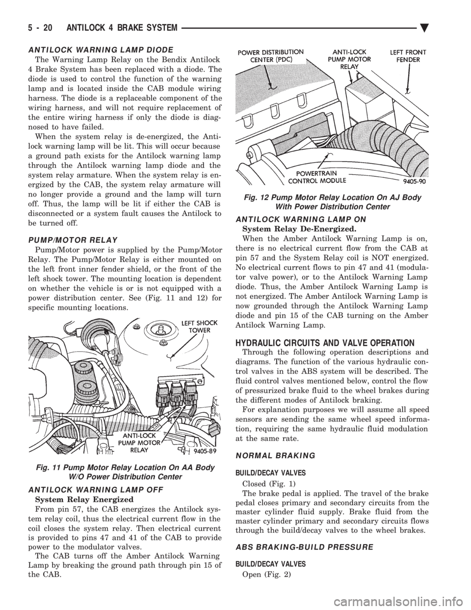
PUMP/MOTOR RELAY
Pump/Motor power is supplied by the Pump/Motor
Relay. The Pump/Motor Relay is either mounted on
the left front inner fender shield, or the front of the
left shock tower. The mounting location is dependent
on whether the vehicle is or is not equipped with a
power distribution center. See (Fig. 11 and 12) for
specific mounting locations.
ANTILOCK WARNING LAMP OFF
System Relay Energized
From pin 57, the CAB energizes the Antilock sys-
tem relay coil, thus the electrical current flow in the
coil closes the system relay. Then electrical current
is provided to pins 47 and 41 of the CAB to provide
power to the modulator valves. The CAB turns off the Amber Antilock Warning
Lamp by breaking the ground path through pin 15 of
the CAB.
ANTILOCK WARNING LAMP ON
System Relay De-Energized.
When the Amber Antilock Warning Lamp is on,
there is no electrical current flow from the CAB at
pin 57 and the System Relay coil is NOT energized.
No electrical current flows to pin 47 and 41 (modula-
tor valve power), or to the Antilock Warning Lamp
diode. Thus, the Amber Antilock Warning Lamp is
not energized. The Amber Antilock Warning Lamp is
now grounded through the Antilock Warning Lamp
diode and pin 15 of the CAB turning on the Amber
Antilock Warning Lamp.
HYDRAULIC CIRCUITS AND VALVE OPERATION
Through the following operation descriptions and
diagrams. The function of the various hydraulic con-
trol valves in the ABS system will be described. The
fluid control valves mentioned below, control the flow
of pressurized brake fluid to the wheel brakes during
the different modes of Antilock braking. For explanation purposes we will assume all speed
sensors are sending the same wheel speed informa-
tion, requiring the same hydraulic fluid modulation
at the same rate.
NORMAL BRAKING
BUILD/DECAY VALVES
Closed (Fig. 1)
The brake pedal is applied. The travel of the brake
pedal closes primary and secondary circuits from the
master cylinder fluid supply. Brake fluid from the
master cylinder primary and secondary circuits flows
through the build/decay valves to the wheel brakes.
ABS BRAKING-BUILD PRESSURE
BUILD/DECAY VALVES
Open (Fig. 2)
Fig. 11 Pump Motor Relay Location On AA Body W/O Power Distribution Center
Fig. 12 Pump Motor Relay Location On AJ BodyWith Power Distribution Center
5 - 20 ANTILOCK 4 BRAKE SYSTEM Ä