1993 CHEVROLET PLYMOUTH ACCLAIM ECU
[x] Cancel search: ECUPage 2303 of 2438
REAR WINDOW GLASS
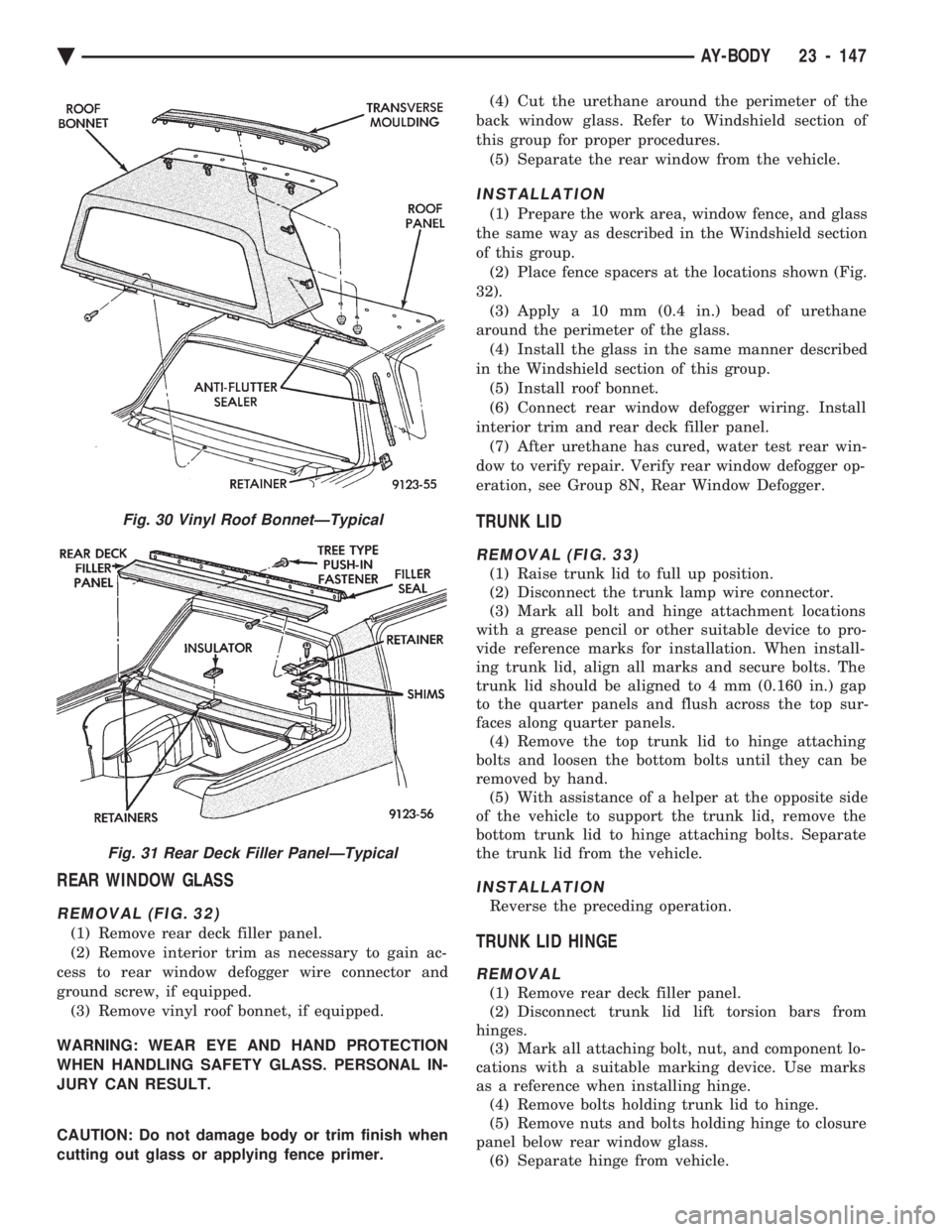
REMOVAL (FIG. 32)
(1) Remove rear deck filler panel.
(2) Remove interior trim as necessary to gain ac-
cess to rear window defogger wire connector and
ground screw, if equipped. (3) Remove vinyl roof bonnet, if equipped.
WARNING: WEAR EYE AND HAND PROTECTION
WHEN HANDLING SAFETY GLASS. PERSONAL IN-
JURY CAN RESULT.
CAUTION: Do not damage body or trim finish when
cutting out glass or applying fence primer. (4) Cut the urethane around the perimeter of the
back window glass. Refer to Windshield section of
this group for proper procedures. (5) Separate the rear window from the vehicle.
INSTALLATION
(1) Prepare the work area, window fence, and glass
the same way as described in the Windshield section
of this group. (2) Place fence spacers at the locations shown (Fig.
32). (3) Apply a 10 mm (0.4 in.) bead of urethane
around the perimeter of the glass. (4) Install the glass in the same manner described
in the Windshield section of this group. (5) Install roof bonnet.
(6) Connect rear window defogger wiring. Install
interior trim and rear deck filler panel. (7) After urethane has cured, water test rear win-
dow to verify repair. Verify rear window defogger op-
eration, see Group 8N, Rear Window Defogger.
TRUNK LID
REMOVAL (FIG. 33)
(1) Raise trunk lid to full up position.
(2) Disconnect the trunk lamp wire connector.
(3) Mark all bolt and hinge attachment locations
with a grease pencil or other suitable device to pro-
vide reference marks for installation. When install-
ing trunk lid, align all marks and secure bolts. The
trunk lid should be aligned to 4 mm (0.160 in.) gap
to the quarter panels and flush across the top sur-
faces along quarter panels. (4) Remove the top trunk lid to hinge attaching
bolts and loosen the bottom bolts until they can be
removed by hand. (5) With assistance of a helper at the opposite side
of the vehicle to support the trunk lid, remove the
bottom trunk lid to hinge attaching bolts. Separate
the trunk lid from the vehicle.
INSTALLATION
Reverse the preceding operation.
TRUNK LID HINGE
REMOVAL
(1) Remove rear deck filler panel.
(2) Disconnect trunk lid lift torsion bars from
hinges. (3) Mark all attaching bolt, nut, and component lo-
cations with a suitable marking device. Use marks
as a reference when installing hinge. (4) Remove bolts holding trunk lid to hinge.
(5) Remove nuts and bolts holding hinge to closure
panel below rear window glass. (6) Separate hinge from vehicle.
Fig. 30 Vinyl Roof BonnetÐTypical
Fig. 31 Rear Deck Filler PanelÐTypical
Ä AY-BODY 23 - 147
Page 2313 of 2438
REFRIGERANT RECYCLING
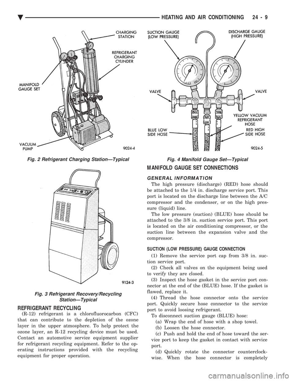
(R-12) refrigerant is a chlorofluorocarbon (CFC)
that can contribute to the depletion of the ozone
layer in the upper atmosphere. To help protect the
ozone layer, an R-12 recycling device must be used.
Contact an automotive service equipment supplier
for refrigerant recycling equipment. Refer to the op-
erating instructions provided with the recycling
equipment for proper operation.
MANIFOLD GAUGE SET CONNECTIONS
GENERAL INFORMATION
The high pressure (discharge) (RED) hose should
be attached to the 1/4 in. discharge service port. This
port is located on the discharge line between the A/C
compressor and the condenser, or on the high pres-
sure (liquid) line. The low pressure (suction) (BLUE) hose should be
attached to the 3/8 in. suction service port. This port
is located on the air conditioning compressor, or the
suction line between the expansion valve and the
compressor.
SUCTION (LOW PRESSURE) GAUGE CONNECTION
(1) Remove the service port cap from 3/8 in. suc-
tion service port. (2) Check all valves on the equipment being used
to verify they are closed. (3) Inspect the hose gasket in the service port con-
nector at the end of the (BLUE) hose. If the gasket is
flawed, replace it. (4) Thread the hose connector onto the service
port. Quickly secure hose connector to the service
port to avoid loosing refrigerant. To disconnect suction gauge (BLUE) hose:(a) Wrap the end of hose with a shop towel.
(b) Loosen the hose connector.
(c) Push and hold the end of hose toward the ser-
vice port to keep the gasket in contact with service
port. (d) Quickly rotate the connector counterclock-
wise. When the hose connector is completely
Fig. 2 Refrigerant Charging StationÐTypical
Fig. 3 Refrigerant Recovery/Recycling StationÐTypical
Fig. 4 Manifold Gauge SetÐTypical
Ä HEATING AND AIR CONDITIONING 24 - 9
Page 2314 of 2438
backed off, immediately point the end of hose toward
floor, as possibly trapped refrigerant in the hose will
be released.(e) Install service port cap.
DISCHARGE (HIGH PRESSURE) GAUGE CONNECTION (1) Remove the service port cap from the 1/4 in.
service port. (2) Check all valves on the equipment being used to
verify they are closed. (3) Inspect the hose gasket in the service port con-
nector at the end of the (RED) hose. If the gasket is
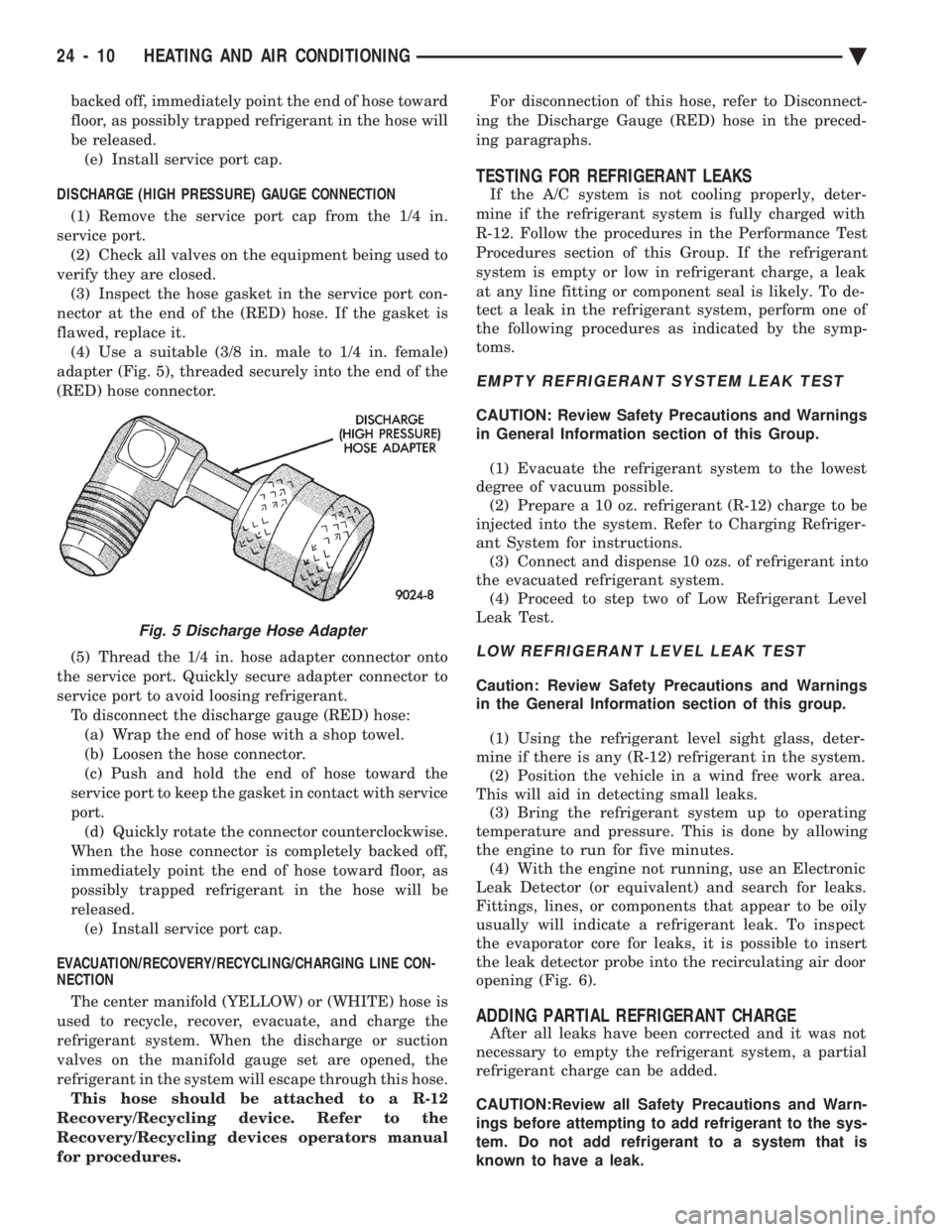
flawed, replace it. (4) Use a suitable (3/8 in. male to 1/4 in. female)
adapter (Fig. 5), threaded securely into the end of the
(RED) hose connector.
(5) Thread the 1/4 in. hose adapter connector onto
the service port. Quickly secure adapter connector to
service port to avoid loosing refrigerant. To disconnect the discharge gauge (RED) hose:(a) Wrap the end of hose with a shop towel.
(b) Loosen the hose connector.
(c) Push and hold the end of hose toward the
service port to keep the gasket in contact with service
port. (d) Quickly rotate the connector counterclockwise.
When the hose connector is completely backed off,
immediately point the end of hose toward floor, as
possibly trapped refrigerant in the hose will be
released. (e) Install service port cap.
EVACUATION/RECOVERY/RECYCLING/CHARGING LINE CON-
NECTION
The center manifold (YELLOW) or (WHITE) hose is
used to recycle, recover, evacuate, and charge the
refrigerant system. When the discharge or suction
valves on the manifold gauge set are opened, the
refrigerant in the system will escape through this hose. This hose should be attached to a R-12
Recovery/Recycling device. Refer to the
Recovery/Recycling devices operators manual
for procedures. For disconnection of this hose, refer to Disconnect-
ing the Discharge Gauge (RED) hose in the preced-
ing paragraphs.
TESTING FOR REFRIGERANT LEAKS
If the A/C system is not cooling properly, deter-
mine if the refrigerant system is fully charged with
R-12. Follow the procedures in the Performance Test
Procedures section of this Group. If the refrigerant
system is empty or low in refrigerant charge, a leak
at any line fitting or component seal is likely. To de-
tect a leak in the refrigerant system, perform one of
the following procedures as indicated by the symp-
toms.
EMPTY REFRIGERANT SYSTEM LEAK TEST
CAUTION: Review Safety Precautions and Warnings
in General Information section of this Group.
(1) Evacuate the refrigerant system to the lowest
degree of vacuum possible. (2) Prepare a 10 oz. refrigerant (R-12) charge to be
injected into the system. Refer to Charging Refriger-
ant System for instructions. (3) Connect and dispense 10 ozs. of refrigerant into
the evacuated refrigerant system. (4) Proceed to step two of Low Refrigerant Level
Leak Test.
LOW REFRIGERANT LEVEL LEAK TEST
Caution: Review Safety Precautions and Warnings
in the General Information section of this group.
(1) Using the refrigerant level sight glass, deter-
mine if there is any (R-12) refrigerant in the system. (2) Position the vehicle in a wind free work area.
This will aid in detecting small leaks. (3) Bring the refrigerant system up to operating
temperature and pressure. This is done by allowing
the engine to run for five minutes. (4) With the engine not running, use an Electronic
Leak Detector (or equivalent) and search for leaks.
Fittings, lines, or components that appear to be oily
usually will indicate a refrigerant leak. To inspect
the evaporator core for leaks, it is possible to insert
the leak detector probe into the recirculating air door
opening (Fig. 6).
ADDING PARTIAL REFRIGERANT CHARGE
After all leaks have been corrected and it was not
necessary to empty the refrigerant system, a partial
refrigerant charge can be added.
CAUTION:Review all Safety Precautions and Warn-
ings before attempting to add refrigerant to the sys-
tem. Do not add refrigerant to a system that is
known to have a leak.
Fig. 5 Discharge Hose Adapter
24 - 10 HEATING AND AIR CONDITIONING Ä
Page 2326 of 2438
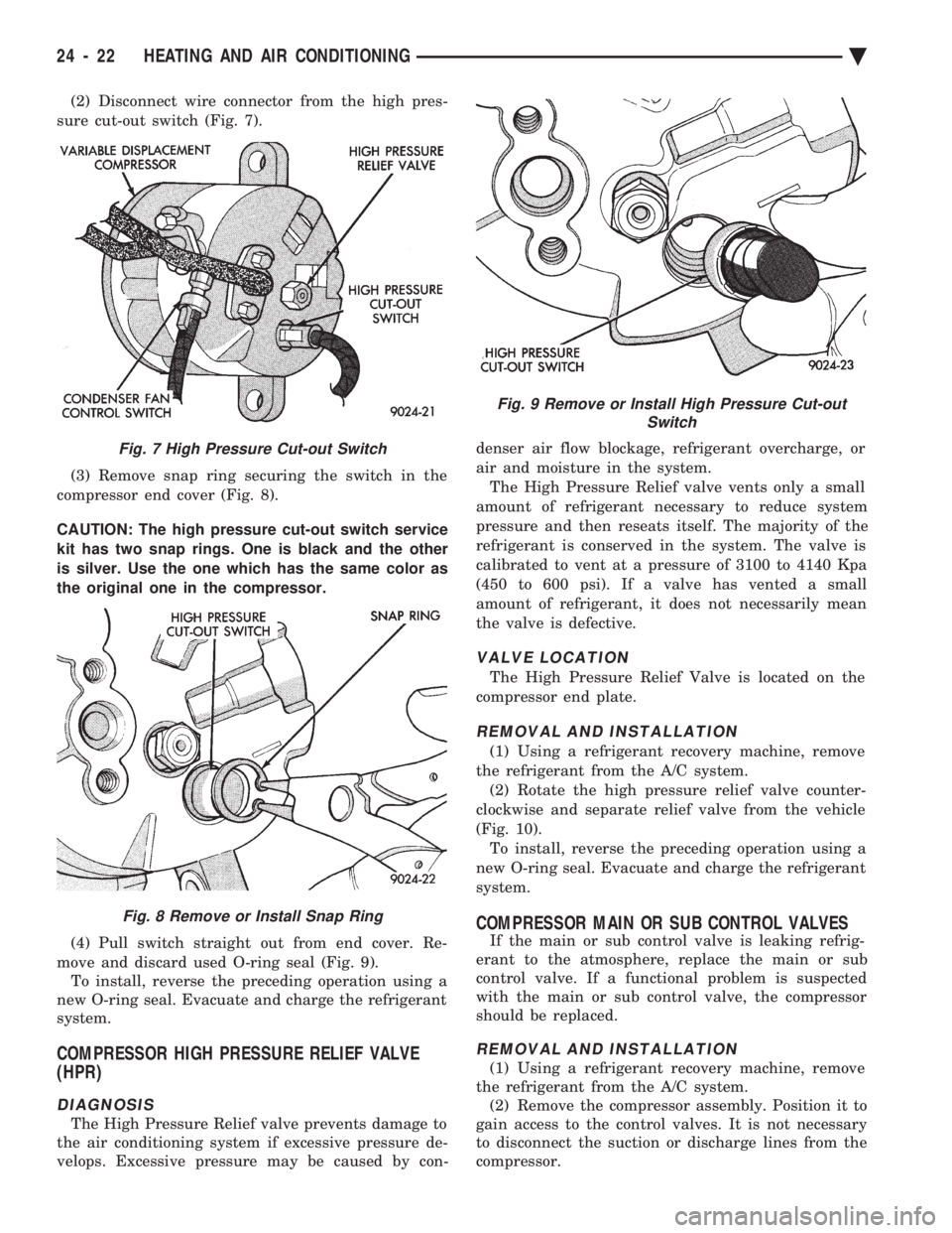
(2) Disconnect wire connector from the high pres-
sure cut-out switch (Fig. 7).
(3) Remove snap ring securing the switch in the
compressor end cover (Fig. 8).
CAUTION: The high pressure cut-out switch service
kit has two snap rings. One is black and the other
is silver. Use the one which has the same color as
the original one in the compressor.
(4) Pull switch straight out from end cover. Re-
move and discard used O-ring seal (Fig. 9). To install, reverse the preceding operation using a
new O-ring seal. Evacuate and charge the refrigerant
system.
COMPRESSOR HIGH PRESSURE RELIEF VALVE
(HPR)
DIAGNOSIS
The High Pressure Relief valve prevents damage to
the air conditioning system if excessive pressure de-
velops. Excessive pressure may be caused by con- denser air flow blockage, refrigerant overcharge, or
air and moisture in the system.
The High Pressure Relief valve vents only a small
amount of refrigerant necessary to reduce system
pressure and then reseats itself. The majority of the
refrigerant is conserved in the system. The valve is
calibrated to vent at a pressure of 3100 to 4140 Kpa
(450 to 600 psi). If a valve has vented a small
amount of refrigerant, it does not necessarily mean
the valve is defective.
VALVE LOCATION
The High Pressure Relief Valve is located on the
compressor end plate.
REMOVAL AND INSTALLATION
(1) Using a refrigerant recovery machine, remove
the refrigerant from the A/C system. (2) Rotate the high pressure relief valve counter-
clockwise and separate relief valve from the vehicle
(Fig. 10). To install, reverse the preceding operation using a
new O-ring seal. Evacuate and charge the refrigerant
system.
COMPRESSOR MAIN OR SUB CONTROL VALVES
If the main or sub control valve is leaking refrig-
erant to the atmosphere, replace the main or sub
control valve. If a functional problem is suspected
with the main or sub control valve, the compressor
should be replaced.
REMOVAL AND INSTALLATION
(1) Using a refrigerant recovery machine, remove
the refrigerant from the A/C system. (2) Remove the compressor assembly. Position it to
gain access to the control valves. It is not necessary
to disconnect the suction or discharge lines from the
compressor.
Fig. 7 High Pressure Cut-out Switch
Fig. 8 Remove or Install Snap Ring
Fig. 9 Remove or Install High Pressure Cut-out Switch
24 - 22 HEATING AND AIR CONDITIONING Ä
Page 2337 of 2438
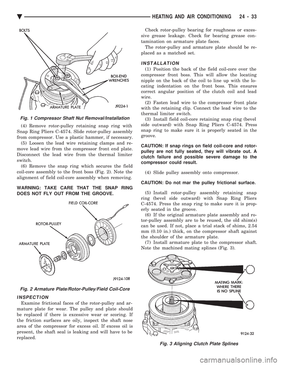
(4) Remove rotor-pulley retaining snap ring with
Snap Ring Pliers C-4574. Slide rotor-pulley assembly
from compressor. Use a plastic hammer, if necessary. (5) Loosen the lead wire retaining clamps and re-
move lead wire from the compressor front end plate.
Disconnect the lead wire from the thermal limiter
switch. (6) Remove the snap ring which secures the field
coil-core assembly to the front boss (Fig. 2). Note the
alignment of field coil-core assembly when removing.
WARNING: TAKE CARE THAT THE SNAP RING
DOES NOT FLY OUT FROM THE GROOVE.
INSPECTION
Examine frictional faces of the rotor-pulley and ar-
mature plate for wear. The pulley and plate should
be replaced if there is excessive wear or scoring. If
the friction surfaces are oily, inspect the shaft nose
area of the compressor for excess oil. If excess oil is
present, the shaft seal is leaking and will have to be
replaced. Check rotor-pulley bearing for roughness or exces-
sive grease leakage. Check for bearing grease con-
tamination on armature plate faces. The rotor-pulley and armature plate should be re-
placed as a matched set.
INSTALLATION
(1) Position the back of the field coil-core over the
compressor front boss. This will allow the locating
nipple on the back of the coil to line up with the lo-
cating indentation on the front boss. This ensures
correct angular position of the clutch coil and lead
wire. (2) Fasten lead wire to the compressor front plate
with the retaining clip. Connect the lead wire to the
thermal limiter switch. (3) Install field coil-core retaining snap ring (bevel
side outward) with Snap Ring Pliers C-4574. Press
snap ring to make sure it is properly seated in the
groove.
CAUTION: If snap rings on field coil-core and rotor-
pulley are not fully seated, they will vibrate out. A
clutch failure and possible severe damage to the
compressor could result.
(4) Slide pulley assembly onto compressor.
CAUTION: Do not mar the pulley frictional surface. (5) Install rotor-pulley assembly retaining snap
ring (bevel side outward) with Snap Ring Pliers
C-4574. Press the snap ring to make sure it is prop-
erly seated in the groove. (6) If the original armature plate assembly and ro-
tor-pulley assembly are to be reused, the old shim(s)
can be used. If not, place a trial stack of shims, 2.54
mm (0.10 in.) thick, on the compressor shaft against
the shoulder of the armature plate. (7) Install armature plate to the compressor shaft.
Note the machined mating splines (Fig. 3).
Fig. 1 Compressor Shaft Nut Removal/Installation
Fig. 2 Armature Plate/Rotor-Pulley/Field Coil-Core
Fig. 3 Aligning Clutch Plate Splines
Ä HEATING AND AIR CONDITIONING 24 - 33
Page 2338 of 2438
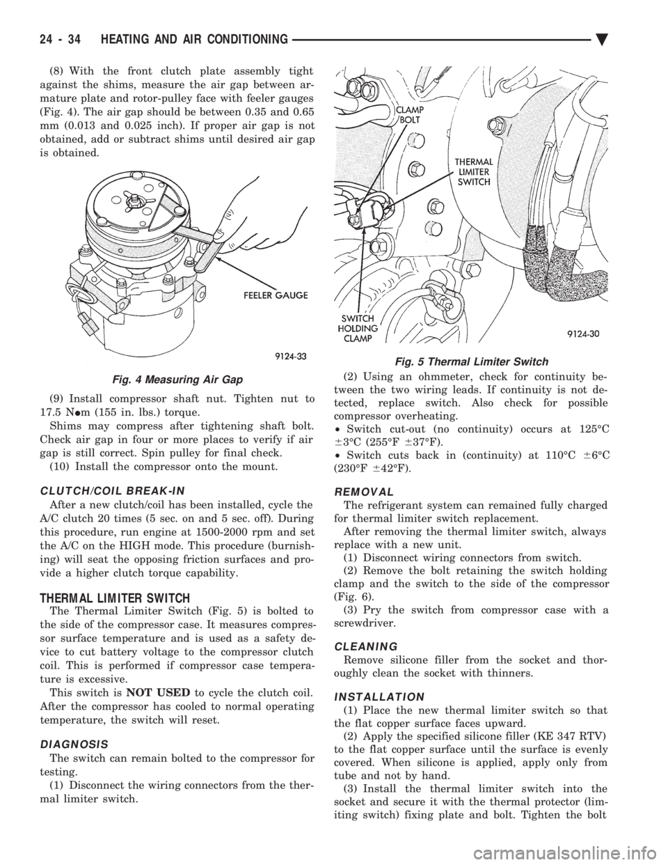
(8) With the front clutch plate assembly tight
against the shims, measure the air gap between ar-
mature plate and rotor-pulley face with feeler gauges
(Fig. 4). The air gap should be between 0.35 and 0.65
mm (0.013 and 0.025 inch). If proper air gap is not
obtained, add or subtract shims until desired air gap
is obtained.
(9) Install compressor shaft nut. Tighten nut to
17.5 N Im (155 in. lbs.) torque.
Shims may compress after tightening shaft bolt.
Check air gap in four or more places to verify if air
gap is still correct. Spin pulley for final check. (10) Install the compressor onto the mount.
CLUTCH/COIL BREAK-IN
After a new clutch/coil has been installed, cycle the
A/C clutch 20 times (5 sec. on and 5 sec. off). During
this procedure, run engine at 1500-2000 rpm and set
the A/C on the HIGH mode. This procedure (burnish-
ing) will seat the opposing friction surfaces and pro-
vide a higher clutch torque capability.
THERMAL LIMITER SWITCH
The Thermal Limiter Switch (Fig. 5) is bolted to
the side of the compressor case. It measures compres-
sor surface temperature and is used as a safety de-
vice to cut battery voltage to the compressor clutch
coil. This is performed if compressor case tempera-
ture is excessive. This switch is NOT USEDto cycle the clutch coil.
After the compressor has cooled to normal operating
temperature, the switch will reset.
DIAGNOSIS
The switch can remain bolted to the compressor for
testing. (1) Disconnect the wiring connectors from the ther-
mal limiter switch. (2) Using an ohmmeter, check for continuity be-
tween the two wiring leads. If continuity is not de-
tected, replace switch. Also check for possible
compressor overheating.
² Switch cut-out (no continuity) occurs at 125ÉC
6 3ÉC (255ÉF 637ÉF).
² Switch cuts back in (continuity) at 110ÉC 66ÉC
(230ÉF 642ÉF).
REMOVAL
The refrigerant system can remained fully charged
for thermal limiter switch replacement. After removing the thermal limiter switch, always
replace with a new unit. (1) Disconnect wiring connectors from switch.
(2) Remove the bolt retaining the switch holding
clamp and the switch to the side of the compressor
(Fig. 6). (3) Pry the switch from compressor case with a
screwdriver.
CLEANING
Remove silicone filler from the socket and thor-
oughly clean the socket with thinners.
INSTALLATION
(1) Place the new thermal limiter switch so that
the flat copper surface faces upward. (2) Apply the specified silicone filler (KE 347 RTV)
to the flat copper surface until the surface is evenly
covered. When silicone is applied, apply only from
tube and not by hand. (3) Install the thermal limiter switch into the
socket and secure it with the thermal protector (lim-
iting switch) fixing plate and bolt. Tighten the bolt
Fig. 4 Measuring Air Gap
Fig. 5 Thermal Limiter Switch
24 - 34 HEATING AND AIR CONDITIONING Ä
Page 2353 of 2438
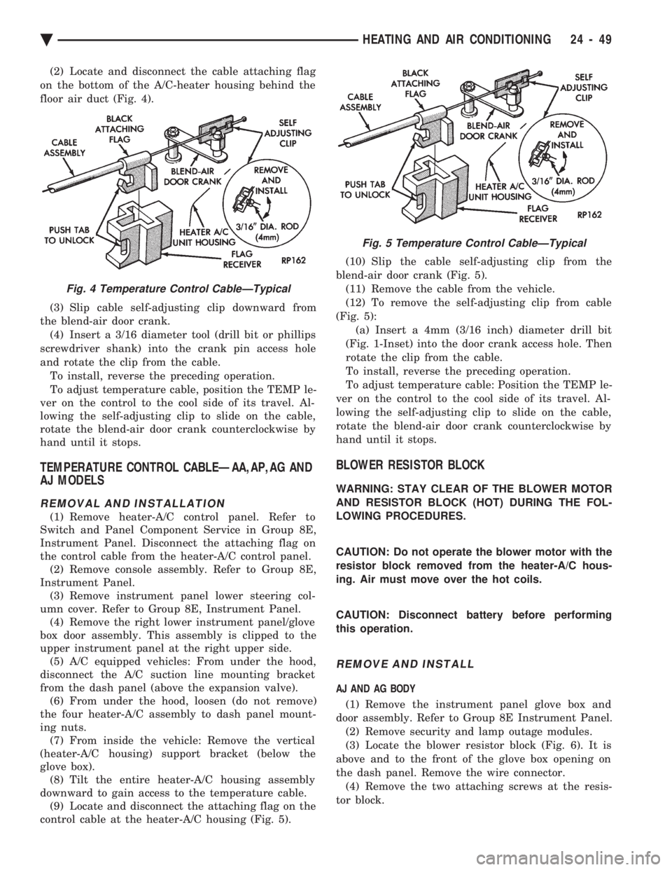
(2) Locate and disconnect the cable attaching flag
on the bottom of the A/C-heater housing behind the
floor air duct (Fig. 4).
(3) Slip cable self-adjusting clip downward from
the blend-air door crank. (4) Insert a 3/16 diameter tool (drill bit or phillips
screwdriver shank) into the crank pin access hole
and rotate the clip from the cable. To install, reverse the preceding operation.
To adjust temperature cable, position the TEMP le-
ver on the control to the cool side of its travel. Al-
lowing the self-adjusting clip to slide on the cable,
rotate the blend-air door crank counterclockwise by
hand until it stops.
TEMPERATURE CONTROL CABLEÐAA,AP,AG AND
AJ MODELS
REMOVAL AND INSTALLATION
(1) Remove heater-A/C control panel. Refer to
Switch and Panel Component Service in Group 8E,
Instrument Panel. Disconnect the attaching flag on
the control cable from the heater-A/C control panel. (2) Remove console assembly. Refer to Group 8E,
Instrument Panel. (3) Remove instrument panel lower steering col-
umn cover. Refer to Group 8E, Instrument Panel. (4) Remove the right lower instrument panel/glove
box door assembly. This assembly is clipped to the
upper instrument panel at the right upper side. (5) A/C equipped vehicles: From under the hood,
disconnect the A/C suction line mounting bracket
from the dash panel (above the expansion valve). (6) From under the hood, loosen (do not remove)
the four heater-A/C assembly to dash panel mount-
ing nuts. (7) From inside the vehicle: Remove the vertical
(heater-A/C housing) support bracket (below the
glove box). (8) Tilt the entire heater-A/C housing assembly
downward to gain access to the temperature cable. (9) Locate and disconnect the attaching flag on the
control cable at the heater-A/C housing (Fig. 5). (10) Slip the cable self-adjusting clip from the
blend-air door crank (Fig. 5). (11) Remove the cable from the vehicle.
(12) To remove the self-adjusting clip from cable
(Fig. 5): (a) Insert a 4mm (3/16 inch) diameter drill bit
(Fig. 1-Inset) into the door crank access hole. Then
rotate the clip from the cable.
To install, reverse the preceding operation.
To adjust temperature cable: Position the TEMP le-
ver on the control to the cool side of its travel. Al-
lowing the self-adjusting clip to slide on the cable,
rotate the blend-air door crank counterclockwise by
hand until it stops.
BLOWER RESISTOR BLOCK
WARNING: STAY CLEAR OF THE BLOWER MOTOR
AND RESISTOR BLOCK (HOT) DURING THE FOL-
LOWING PROCEDURES.
CAUTION: Do not operate the blower motor with the
resistor block removed from the heater-A/C hous-
ing. Air must move over the hot coils.
CAUTION: Disconnect battery before performing
this operation.
REMOVE AND INSTALL
AJ AND AG BODY
(1) Remove the instrument panel glove box and
door assembly. Refer to Group 8E Instrument Panel. (2) Remove security and lamp outage modules.
(3) Locate the blower resistor block (Fig. 6). It is
above and to the front of the glove box opening on
the dash panel. Remove the wire connector. (4) Remove the two attaching screws at the resis-
tor block.
Fig. 4 Temperature Control CableÐTypical
Fig. 5 Temperature Control CableÐTypical
Ä HEATING AND AIR CONDITIONING 24 - 49
Page 2360 of 2438
stabilize to the pressure recorded in step 7. If the
pressure does not stabilize, replace the expansion
valve.When expansion valve tests are complete, refer to
Heater and A/C Performance Tests and remove all test
equipment before returning vehicle to use.
SILVER EXPANSION VALVE TEST
Expansion valve tests should be performed af-
ter compressor tests. Liquid CO
2is required to test the expansion
valve. It is available from most welding supply
facilities. CO
2is also available from companies
which service and sell fire extinguishers. Review Safety Precautions and Warnings in the
General Information section of this Group. The work
area and vehicle must be 21ÉC to 27ÉC (70ÉF to 85ÉF)
when testing expansion valve. To test the expansion
valve: (1) Connect a charging station or manifold gauge set
to the refrigerant system service ports. (2) Verify the refrigerant charge level using the sight
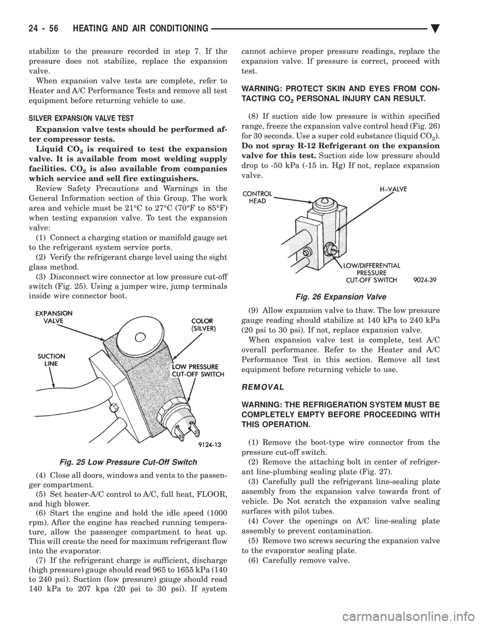
glass method. (3) Disconnect wire connector at low pressure cut-off
switch (Fig. 25). Using a jumper wire, jump terminals
inside wire connector boot.
(4) Close all doors, windows and vents to the passen-
ger compartment. (5) Set heater-A/C control to A/C, full heat, FLOOR,
and high blower. (6) Start the engine and hold the idle speed (1000
rpm). After the engine has reached running tempera-
ture, allow the passenger compartment to heat up.
This will create the need for maximum refrigerant flow
into the evaporator. (7) If the refrigerant charge is sufficient, discharge
(high pressure) gauge should read 965 to 1655 kPa (140
to 240 psi). Suction (low pressure) gauge should read
140 kPa to 207 kpa (20 psi to 30 psi). If system cannot achieve proper pressure readings, replace the
expansion valve. If pressure is correct, proceed with
test.
WARNING: PROTECT SKIN AND EYES FROM CON-
TACTING CO
2PERSONAL INJURY CAN RESULT.
(8) If suction side low pressure is within specified
range, freeze the expansion valve control head (Fig. 26)
for 30 seconds. Use a super cold substance (liquid CO
2).
Do not spray R-12 Refrigerant on the expansion
valve for this test. Suction side low pressure should
drop to -50 kPa (-15 in. Hg) If not, replace expansion
valve.
(9) Allow expansion valve to thaw. The low pressure
gauge reading should stabilize at 140 kPa to 240 kPa
(20 psi to 30 psi). If not, replace expansion valve. When expansion valve test is complete, test A/C
overall performance. Refer to the Heater and A/C
Performance Test in this section. Remove all test
equipment before returning vehicle to use.
REMOVAL
WARNING: THE REFRIGERATION SYSTEM MUST BE
COMPLETELY EMPTY BEFORE PROCEEDING WITH
THIS OPERATION.
(1) Remove the boot-type wire connector from the
pressure cut-off switch. (2) Remove the attaching bolt in center of refriger-
ant line-plumbing sealing plate (Fig. 27). (3) Carefully pull the refrigerant line-sealing plate
assembly from the expansion valve towards front of
vehicle. Do Not scratch the expansion valve sealing
surfaces with pilot tubes. (4) Cover the openings on A/C line-sealing plate
assembly to prevent contamination. (5) Remove two screws securing the expansion valve
to the evaporator sealing plate. (6) Carefully remove valve.
Fig. 25 Low Pressure Cut-Off Switch
Fig. 26 Expansion Valve
24 - 56 HEATING AND AIR CONDITIONING Ä