1993 CHEVROLET PLYMOUTH ACCLAIM Ignition coil
[x] Cancel search: Ignition coilPage 1885 of 2438
3.3L AND 3.8L MULTI-PORT FUEL INJECTIONÐSYSTEM OPERATION INDEX
page page
Air Conditioning (A/C) Clutch RelayÐPCM Output. 150
Air Conditioning Switch SenseÐPCM Input .... 147
Auto Shutdown (ASD) Relay and Fuel Pump RelayÐPCM Output .................... 151
Battery VoltageÐPCM Input ............... 147
Brake SwitchÐPCM Input ................. 147
Camshaft Position SensorÐPCM Input ....... 147
Canister Purge SolenoidÐPCM Output ....... 151
CCD Bus .............................. 146
Crankshaft Position SensorÐPCM Input ...... 148
Data Link ConnectorÐPCM Output .......... 152
Electric EGR Transducer (EET) SolenoidÐPCM Output .............................. 152
Engine Coolant Temperature SensorÐPCM Input. 148
Fuel Injectors and Fuel Rail Assembly ........ 155
Fuel InjectorsÐPCM Output ............... 152
Fuel Pressure Regulator .................. 156
Fuel Supply Circuit ...................... 155
General Information ...................... 145
Generator FieldÐPCM Output .............. 150
Heated Oxygen Sensor (O2Sensor)ÐPCM Input. 149
Idle Air Control MotorÐPCM Output ......... 151
Ignition CoilÐPCM Output ................. 153
Malfunction Indicator Lamp (Check Engine Lamp)ÐPCM Output ................... 151
Manifold Absolute Pressure (MAP) SensorÐPCM Input ................................ 149
Modes of Operation ...................... 153
Powertrain Control Module ................. 146
Radiator Fan RelayÐPCM Output ........... 153
Speed Control SolenoidsÐPCM Output ....... 153
Speed ControlÐPCM Input ................ 150
System Diagnosis ....................... 146
TachometerÐPCM Output ................. 153
Throttle Body ........................... 155
Throttle Position Sensor (TPS)ÐPCM Input .... 150
Transaxle Control ModuleÐPCM Output ...... 152
Transaxle Park/Neutral SwitchÐPCM Input .... 150
Vehicle Speed and Distance InputÐPCM Input . 150
GENERAL INFORMATION
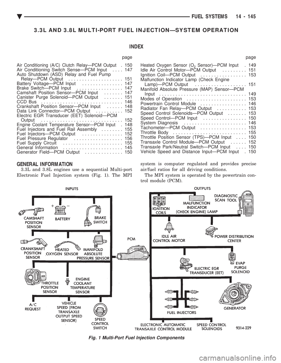
3.3L and 3.8L engines use a sequential Multi-port
Electronic Fuel Injection system (Fig. 1). The MPI system is computer regulated and provides precise
air/fuel ratios for all driving conditions.
The MPI system is operated by the powertrain con-
trol module (PCM).
Fig. 1 Multi-Port Fuel Injection Components
Ä FUEL SYSTEMS 14 - 145
Page 1886 of 2438
The PCM regulates ignition timing, air-fuel ratio,
emission control devices, cooling fan, charging sys-
tem, idle speed and speed control. Various sensors
provide the inputs necessary for the PCM to correctly
operate these systems. In addition to the sensors,
various switches also provide inputs to the PCM. All inputs to the PCM are converted into signals.
The PCM can adapt its programming to meet chang-
ing operating conditions. Fuel is injected into the intake port above the in-
take valve in precise metered amounts through elec-
trically operated injectors. The PCM fires the
injectors in a specific sequence. The PCM maintains
an air fuel ratio of 14.7 parts air to 1 part fuel by
constantly adjusting injector pulse width. Injector
pulse width is the length of time the injector is ener-
gized. The PCM adjusts injector pulse width by opening
and closing the ground path to the injector. Engine
RPM (speed) and manifold absolute pressure (air
density) are the primary inputs that determine injec-
tor pulse width.
SYSTEM DIAGNOSIS
The PCM tests many of its own input and output
circuits. If a fault is found in a major system, the in-
formation is stored in memory. Technicians can dis-
play fault information through the malfunction
indicator lamp (instrument panel Check Engine
lamp) or by connecting the DRBII scan tool. For di-
agnostic trouble code information, refer to the 3.3L/
3.8L Multi-Point Fuel InjectionÐOn-Board
Diagnostics section of this group.
CCD BUS
Various modules exchange information through a
communications port called the CCD Bus. The pow-
ertrain control module (PCM) transmits engine RPM
and vehicle load information on the CCD Bus.
POWERTRAIN CONTROL MODULE
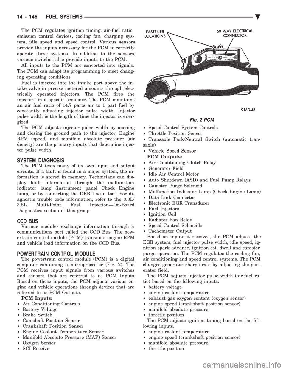
The powertrain control module (PCM) is a digital
computer containing a microprocessor (Fig. 2). The
PCM receives input signals from various switches
and sensors that are referred to as PCM Inputs.
Based on these inputs, the PCM adjusts various en-
gine and vehicle operations through devices that are
referred to as PCM Outputs. PCM Inputs:
² Air Conditioning Controls
² Battery Voltage
² Brake Switch
² Camshaft Position Sensor
² Crankshaft Position Sensor
² Engine Coolant Temperature Sensor
² Manifold Absolute Pressure (MAP) Sensor
² Oxygen Sensor
² SCI Receive ²
Speed Control System Controls
² Throttle Position Sensor
² Transaxle Park/Neutral Switch (automatic tran-
saxle)
² Vehicle Speed Sensor
PCM Outputs:
² Air Conditioning Clutch Relay
² Generator Field
² Idle Air Control Motor
² Auto Shutdown (ASD) and Fuel Pump Relays
² Canister Purge Solenoid
² Malfunction Indicator Lamp (Check Engine Lamp)
² Data Link Connector
² Electronic EGR Transducer
² Fuel Injectors
² Ignition Coil
² Radiator Fan Relay
² Speed Control Solenoids
² Tachometer Output
Based on inputs it receives, the PCM adjusts the
EGR system, fuel injector pulse width, idle speed, ig-
nition spark advance, ignition coil dwell and canister
purge operation. The PCM regulates the cooling fan,
air conditioning and speed control systems. The PCM
changes generator charge rate by adjusting the gen-
erator field. The PCM adjusts injector pulse width (air-fuel ra-
tio) based on the following inputs.
² battery voltage
² engine coolant temperature
² exhaust gas oxygen content (oxygen sensor)
² engine speed (crankshaft position sensor)
² manifold absolute pressure
² throttle position
The PCM adjusts ignition timing based on the fol-
lowing inputs.
² engine coolant temperature
² engine speed (crankshaft position sensor)
² manifold absolute pressure
² throttle position
Fig. 2 PCM
14 - 146 FUEL SYSTEMS Ä
Page 1891 of 2438
within a range of 12.9 to 15.0 volts. Refer to Group
8A for charging system information.
AUTO SHUTDOWN (ASD) RELAY AND FUEL PUMP
RELAYÐPCM OUTPUT
The PCM operates the auto shutdown (ASD) relay
and fuel pump relay through one ground path. The
PCM operates the relays by switching the ground
path on and off. Both relays turn on and off at the
same time. The ASD relay connects battery voltage to the fuel
injector and ignition coil. The fuel pump relay con-
nects battery voltage to the fuel pump and oxygen
sensor heating element. The PCM turns the ground path off when the igni-
tion switch is in the Off position. Both relays are off.
When the ignition switch is in the On or Crank po-
sition, the PCM monitors the crankshaft position
sensor and camshaft position sensor signals to deter-
mine engine speed and ignition timing (coil dwell). If
the PCM does not receive the crankshaft position
sensor and camshaft position sensor signals when the
ignition switch is in the Run position, it de-energizes
both relays. When the relays are de-energized, bat-
tery voltage is not supplied to the fuel injector, igni-
tion coil, fuel pump and oxygen sensor heating
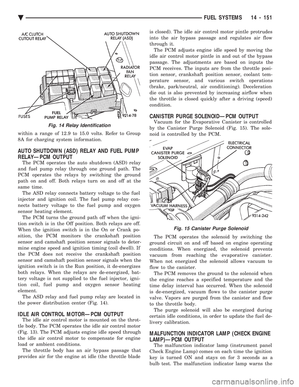
element. The ASD relay and fuel pump relay are located in
the power distribution center (Fig. 14).
IDLE AIR CONTROL MOTORÐPCM OUTPUT
The idle air control motor is mounted on the throt-
tle body. The PCM operates the idle air control motor
(Fig. 13). The PCM adjusts engine idle speed through
the idle air control motor to compensate for engine
load or ambient conditions. The throttle body has an air bypass passage that
provides air for the engine at idle (the throttle blade is closed). The idle air control motor pintle protrudes
into the air bypass passage and regulates air flow
through it. The PCM adjusts engine idle speed by moving the
idle air control motor pintle in and out of the bypass
passage. The adjustments are based on inputs the
PCM receives. The inputs are from the throttle posi-
tion sensor, crankshaft position sensor, coolant tem-
perature sensor, and various switch operations
(brake, park/neutral, air conditioning). Deceleration
die out is also prevented by increasing airflow when
the throttle is closed quickly after a driving (speed)
condition.
CANISTER PURGE SOLENOIDÐPCM OUTPUT
Vacuum for the Evaporative Canister is controlled
by the Canister Purge Solenoid (Fig. 15). The sole-
noid is controlled by the PCM.
The PCM operates the solenoid by switching the
ground circuit on and off based on engine operating
conditions. When energized, the solenoid prevents
vacuum from reaching the evaporative canister.
When not energized the solenoid allows vacuum to
flow to the canister. The PCM removes the ground to the solenoid when
the engine reaches a specified temperature and the
time delay interval has occurred. When the solenoid
is de-energized, vacuum flows to the canister purge
valve. Vapors are purged from the canister and flow
to the throttle body. The purge solenoid will also be energized during
certain idle conditions, in order to update the fuel de-
livery calibration.
MALFUNCTION INDICATOR LAMP (CHECK ENGINE
LAMP)ÐPCM OUTPUT
The malfunction indicator lamp (instrument panel
Check Engine Lamp) comes on each time the ignition
key is turned ON and stays on for 3 seconds as a
bulb test. The malfunction indicator lamp warns the
Fig. 14 Relay Identification
Fig. 15 Canister Purge Solenoid
Ä FUEL SYSTEMS 14 - 151
Page 1893 of 2438
the PCM determines crankshaft position, it begins
energizing the injectors in sequence.The auto shutdown (ASD) relay supplies battery
voltage to the injectors. The PCM provides the
ground path for the injectors. By switching the
ground path on and off, the PCM adjusts injector
pulse width. Pulse width is the amount of time the
injector is energized. The PCM adjusts injector pulse
width based on inputs it receives.
IGNITION COILÐPCM OUTPUT
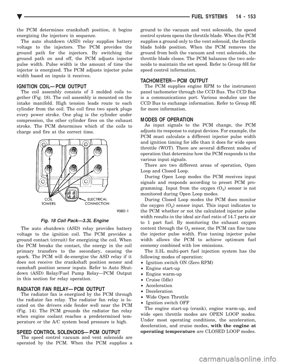
The coil assembly consists of 3 molded coils to-
gether (Fig. 18). The coil assembly is mounted on the
intake manifold. High tension leads route to each
cylinder from the coil. The coil fires two spark plugs
every power stroke. One plug is the cylinder under
compression, the other cylinder fires on the exhaust
stroke. The PCM determines which of the coils to
charge and fire at the correct time.
The auto shutdown (ASD) relay provides battery
voltage to the ignition coil. The PCM provides a
ground contact (circuit) for energizing the coil. When
the PCM breaks the contact, the energy in the coil
primary transfers to the secondary, causing the
spark. The PCM will de-energize the ASD relay if it
does not receive the crankshaft position sensor and
camshaft position sensor inputs. Refer to Auto Shut-
down (ASD) Relay/Fuel Pump RelayÐPCM Output
in this section for relay operation.
RADIATOR FAN RELAYÐPCM OUTPUT
The radiator fan is energized by the PCM through
the radiator fan relay. The radiator fan relay is lo-
cated on the drivers side fender well near the PCM
(Fig. 14). The PCM grounds the radiator fan relay
when engine coolant reaches a predetermined tem-
perature or the A/C system head pressure is high.
SPEED CONTROL SOLENOIDSÐPCM OUTPUT
The speed control vacuum and vent solenoids are
operated by the PCM. When the PCM supplies a ground to the vacuum and vent solenoids, the speed
control system opens the throttle blade. When the PCM
supplies a ground only to the vent solenoid, the throttle
blade holds position. When the PCM removes the
ground from both the vacuum and vent solenoids, the
throttle blade closes. The PCM balances the two sole-
noids to maintain the set speed. Refer to Group 8H for
speed control information.
TACHOMETERÐPCM OUTPUT
The PCM supplies engine RPM to the instrument
panel tachometer through the CCD Bus. The CCD Bus
is a communications port. Various modules use the
CCD Bus to exchange information. Refer to Group 8E
for more information.
MODES OF OPERATION
As input signals to the PCM change, the PCM
adjusts its response to output devices. For example, the
PCM must calculate a different injector pulse width
and ignition timing for idle than it does for wide open
throttle (WOT). There are several different modes of
operation that determine how the PCM responds to the
various input signals. There are two different areas of operation, Open
Loop and Closed Loop. During Open Loop modes the PCM receives input
signals and responds according to preset PCM pro-
gramming. Input from the oxygen (O
2) sensor is not
monitored during Open Loop modes. During Closed Loop modes the PCM does monitor
the oxygen (O
2) sensor input. This input indicates to
the PCM whether or not the calculated injector pulse
width results in the ideal air-fuel ratio of 14.7 parts air
to 1 part fuel. By monitoring the exhaust oxygen
content through the O
2sensor, the PCM can fine tune
the injector pulse width. Fine tuning injector pulse
width allows the PCM to achieve optimum fuel
economy combined with low emissions. The 3.3L multi-port fuel injection system has the
following modes of operation:
² Ignition switch ON (Zero RPM)
² Engine start-up
² Engine warm-up
² Cruise (Idle)
² Acceleration
² Deceleration
² Wide Open Throttle
² Ignition switch OFF
The engine start-up (crank), engine warm-up, and
wide open throttle modes are OPEN LOOP modes.
Under most operating conditions, the acceleration,
deceleration, and cruise modes, with the engine at
operating temperature are CLOSED LOOP modes.
Fig. 18 Coil PackÐ3.3L Engine
Ä FUEL SYSTEMS 14 - 153
Page 1894 of 2438
IGNITION SWITCH ON (ZERO RPM) MODE When the multi-port fuel injection system is acti-
vated by the ignition switch, the following actions oc-
cur:
² The PCM determines atmospheric air pressure
from the MAP sensor input to determine basic fuel
strategy.
² The PCM monitors the coolant temperature sensor
and throttle position sensor input. The PCM modifies
fuel strategy based on this input. When the key is in the ON position and the engine
is not running (zero rpm), the auto shutdown (ASD)
relay and fuel pump relay are not energized. There-
fore battery voltage is not supplied to the fuel pump,
ignition coil, fuel injectors or oxygen sensor heating
element.
ENGINE START-UP MODE
This is an OPEN LOOP mode. The following ac-
tions occur when the starter motor is engaged. If the PCM receives the camshaft position sensor
and crankshaft position sensor signals, it energizes
the auto shutdown (ASD) relay and fuel pump relay.
These relays supply battery voltage to the fuel pump,
fuel injectors, ignition coil, and oxygen sensor heat-
ing element. If the PCM does not receive the cam-
shaft position sensor and crankshaft position sensor
signals within approximately one second, it de-ener-
gizes the ASD relay and fuel pump relay. The PCM energizes all six injectors until it deter-
mines crankshaft position from the camshaft position
sensor and crankshaft position sensor signals. The
PCM determines crankshaft position within 1 engine
revolution. After determining crankshaft position, the PCM
begins energizing the injectors in sequence. The PCM
adjusts injector pulse width and controls injector syn-
chronization by turning the individual ground paths
to the injectors On and Off. When the engine idles within 664 RPM of its tar-
get RPM, the PCM compares current MAP sensor
value with the atmospheric pressure value received
during the Ignition Switch On (Zero RPM) mode. If
the PCM does not detect a minimum difference be-
tween the two values, it sets a MAP fault into mem-
ory. Once the ASD and fuel pump relays have been en-
ergized, the PCM:
² Determines injector pulse width based on battery
voltage, coolant temperature, engine rpm and the
number of engine revolutions since cranking was ini-
tiated.
ENGINE WARM-UP MODE This is a OPEN LOOP mode. The following inputs
are received by the PCM:
² engine coolant temperature ²
manifold absolute pressure (MAP)
² engine speed (crankshaft position sensor)
² throttle position
² A/C switch
² battery voltage
The PCM adjusts injector pulse width and controls
injector synchronization by turning the individual
ground paths to the injectors On and Off. The PCM adjusts ignition timing and engine idle
speed. Engine idle speed is adjusted through the idle
air control motor.
CRUISE OR IDLE MODE
When the engine is at operating temperature this
is a CLOSED LOOP mode. During cruising speed the
following inputs are received by the PCM:
² engine coolant temperature
² manifold absolute pressure
² engine speed (crankshaft position sensor)
² throttle position
² exhaust gas oxygen content
² A/C control positions
² battery voltage
The PCM adjusts injector pulse width and controls
injector synchronization by turning the individual
ground paths to the injectors On and Off. The PCM adjusts engine idle speed and ignition
timing. The PCM adjusts the air/fuel ratio according
to the oxygen content in the exhaust gas.
ACCELERATION MODE This is a CLOSED LOOP mode. The PCM recog-
nizes an abrupt increase in throttle position or MAP
pressure as a demand for increased engine output
and vehicle acceleration. The PCM increases injector
pulse width in response to increased fuel demand.
DECELERATION MODE This is a CLOSED LOOP mode. During decelera-
tion the following inputs are received by the PCM:
² engine coolant temperature
² manifold absolute pressure
² engine speed
² throttle position
² exhaust gas oxygen content
² A/C control positions
² battery voltage
The PCM may receive a closed throttle input from
the throttle position sensor (TPS) when it senses an
abrupt decrease in manifold pressure. This indicates
a hard deceleration. The PCM will reduce injector
pulse width. This helps maintain better control of the
air-fuel mixture (as sensed through the O
2sensor).
During a closed throttle deceleration condition, the
PCM grounds the exhaust gas recirculation (EGR)
solenoid. When the solenoid is grounded, EGR func-
tion stops.
14 - 154 FUEL SYSTEMS Ä
Page 1897 of 2438
3.3L AND 3.8L MULTI-PORT FUEL INJECTIONÐGENERAL DIAGNOSIS INDEX
page page
Fuel System Diagram .................... 157 Visual Inspection........................ 157
FUEL SYSTEM DIAGRAM
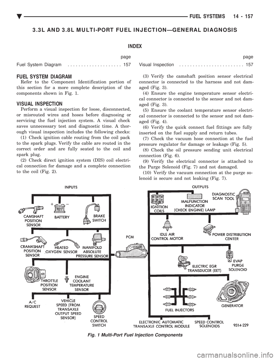
Refer to the Component Identification portion of
this section for a more complete description of the
components shown in Fig. 1.
VISUAL INSPECTION
Perform a visual inspection for loose, disconnected,
or misrouted wires and hoses before diagnosing or
servicing the fuel injection system. A visual check
saves unnecessary test and diagnostic time. A thor-
ough visual inspection includes the following checks: (1) Check ignition cable routing from the coil pack
to the spark plugs. Verify the cable are routed in the
correct order and are fully seated to the coil and
spark plug. (2) Check direct ignition system (DIS) coil electri-
cal connection for damage and a complete connection
to the coil (Fig. 2). (3) Verify the camshaft position sensor electrical
connector is connected to the harness and not dam-
aged (Fig. 3). (4) Ensure the engine temperature sensor electri-
cal connector is connected to the sensor and not dam-
aged (Fig. 3). (5) Ensure the coolant temperature sensor electri-
cal connector is connected to the sensor and not dam-
aged (Fig. 4). (6) Verify the quick connect fuel fittings are fully
inserted on the fuel supply and return tubes. (7) Check the vacuum hose connection at the fuel
pressure regulator for damage or leakage (Fig. 5). (8) Check the oil pressure sending unit electrical
connection (Fig. 6). (9) Verify the electrical connector is attached to
the Purge Solenoid (Fig. 7) and not damaged. (10) Verify the vacuum connection at the purge so-
lenoid is secure and not leaking (Fig. 7).
Fig. 1 Multi-Port Fuel Injection Components
Ä FUEL SYSTEMS 14 - 157
Page 1898 of 2438
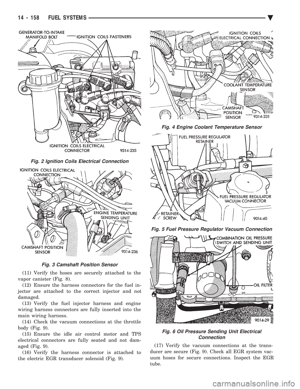
(11) Verify the hoses are securely attached to the
vapor canister (Fig. 8). (12) Ensure the harness connectors for the fuel in-
jector are attached to the correct injector and not
damaged. (13) Verify the fuel injector harness and engine
wiring harness connectors are fully inserted into the
main wiring harness. (14) Check the vacuum connections at the throttle
body (Fig. 9). (15) Ensure the idle air control motor and TPS
electrical connectors are fully seated and not dam-
aged (Fig. 9). (16) Verify the harness connector is attached to
the electric EGR transducer solenoid (Fig. 9). (17) Verify the vacuum connections at the trans-
ducer are secure (Fig. 9). Check all EGR system vac-
uum hoses for secure connections. Inspect the EGR
tube.
Fig. 2 Ignition Coils Electrical Connection
Fig. 3 Camshaft Position Sensor
Fig. 4 Engine Coolant Temperature Sensor
Fig. 5 Fuel Pressure Regulator Vacuum Connection
Fig. 6 Oil Pressure Sending Unit Electrical Connection
14 - 158 FUEL SYSTEMS Ä
Page 1903 of 2438
line. However, these could result in a rich or lean
condition causing an oxygen sensor fault to be stored in
the PCM. Secondary Ignition Circuit - The PCM cannot
detect an inoperative ignition coil, fouled or worn spark
plugs, ignition cross firing, or open spark plug cables. Engine Timing - The PCM cannot detect an incor-
rectly indexed timing chain, camshaft sprocket and
crankshaft sprocket. However, these could result in a
rich or lean condition causing an oxygen sensor fault to
be stored in the PCM. Cylinder Compression - The PCM cannot detect
uneven, low, or high engine cylinder compression. Exhaust System - The PCM cannot detect a
plugged, restricted or leaking exhaust system. Fuel Injector Malfunctions - The PCM cannot
determine if a fuel injector is clogged, the needle is
sticking or the wrong injector is installed. However,
these could result in a rich or lean condition causing an
oxygen sensor fault to be stored in the PCM. Excessive Oil Consumption - Although the PCM
monitors exhaust stream oxygen content when the
system is in closed loop, it cannot determine excessive
oil consumption. Throttle Body Air Flow - The PCM cannot detect a
clogged or restricted air cleaner inlet or filter element. Evaporative System - The PCM will not detect a
restricted, plugged or loaded evaporative purge canis-
ter. Vacuum Assist - Leaks or restrictions in the
vacuum circuits of vacuum assisted engine control
system devices are not monitored by the PCM. How-
ever, these could result in a MAP sensor fault being
stored in the PCM. PCM System Ground - The PCM cannot determine
a poor system ground. However, a diagnostic trouble
code may be generated as a result of this condition. PCM Connector Engagement - The PCM cannot
determine spread or damaged connector pins. How-
ever, a diagnostic trouble code may be generated as a
result of this condition.
HIGH AND LOW LIMITS
The powertrain control module (PCM) compares in-
put signal voltages from each input device with estab-
lished high and low limits for the device. If the input
voltage is not within limits and other diagnostic
trouble code criteria are met, a diagnostic trouble code
will be stored in memory. Other diagnostic trouble code
criteria might include engine RPM limits or input
voltages from other sensors or switches that must be
present before a fault condition can be verified.
DIAGNOSTIC TROUBLE CODE DESCRIPTION
A diagnostic trouble code indicates that the power-
train control module (PCM) has recognized an abnor- mal condition in the system. Diagnostic trouble codes
can be obtained from the malfunction indicator lamp
(Check Engine lamp on the instrument panel) or from
the DRBII scan tool. Diagnostic trouble codes indicate
the results of a failure but do not identify the failed
component directly.
SYSTEM TESTS
WARNING: APPLY PARKING BRAKE AND/OR BLOCK
WHEELS BEFORE PERFORMING ANY TEST ON AN
OPERATING ENGINE.
OBTAINING DIAGNOSTIC TROUBLE CODES
(1) Connect the DRBII scan tool to the data link
connector located in the engine compartment near the
driver side strut tower (Fig. 1). (2) Start the engine if possible, cycle the transaxle
selector and the A/Cswitch if applicable. Shut off the
engine. (3) Turn the ignition switch on, access Read Fault
Screen. Record all the fault messages shown on the
DRBII scan tool. Observe the malfunction indicator
lamp (check engine lamp on the instrument panel). The
lamp should light for 2 seconds then go out (bulb
check). Diagnostic trouble code erasure; access erase
diagnostic trouble code data
STATE DISPLAY TEST MODE
The switch inputs used by the powertrain control
module (PCM) have only two recognized states, HIGH
and LOW. For this reason, the PCM cannot recognize
the difference between a selected switch position ver-
sus an open circuit, a short circuit, or a defective
switch. If the change is displayed, it can be assumed
that the entire switch circuit to the PCM is functional.
From the state display screen access either State
Display Inputs and Outputs or State Display Sensors.
STATE DISPLAY INPUTS AND OUTPUTS
Connect the DRBII scan tool to the vehicle and access
the State Display screen. Then access Inputs and
Outputs. The following is a list of the engine control
system functions accessible through the Inputs and
Outputs screen. Park/Neutral Switch
Speed Control Resume
Brake Switch
Speed Control On/Off
Speed Control Set
A/C Switch Sense
S/C Vent Solenoid
Ä FUEL SYSTEMS 14 - 163