1993 CHEVROLET DYNASTY oil
[x] Cancel search: oilPage 250 of 2438

lic assembly with a blunt prying tool (Fig. 12). Use a
rocking motion to help disengage reservoir from
grommets while prying. BE EXTREMELY CARE-
FUL TO AVOID DAMAGING OR PUNCTURING
RESERVOIR DURING THIS PROCEDURE.
(6) Remove the brake fluid level sensor switch
from the reservoir. Remove switch by compressing
the retaining barbs (Fig. 13) on the end of the switch
and then slide switch out of the brake fluid reservoir
(Fig. 14) (7) Using fingers, remove the 3 reservoir grommets
(Fig. 14) from the hydraulic assembly or reservoir, and
discard. Grommets must not to be reused when
reservoir is installed on hydraulic assembly.
INSTALL (1) Thoroughly lubricate the new reservoir grom-
mets with clean brake fluid and install on reservoir
outlet ports (Fig. 14). The new reservoir grommets
supplied with reservoir, must ALWAYS be used. (2) Install brake fluid level switch into brake fluid
reservoir (FIG. 14). (3) Press reservoir into hydraulic assembly BY
HAND , using a rocking motion to help seat reservoir
into hydraulic assembly. Be sure that grommets are
fully seated in the hydraulic assembly. DO NOT AT-
TEMPT TO POUND RESERVOIR INTO HY-
DRAULIC ASSEMBLY, USING A HAMMER. (4) Using needle nose pliers, install the 3 brake fluid
reservoir to hydraulic assembly retaining pins (Fig.
11). Make sure that pins are fully installed with barbs
extending past reservoir on opposite side. (5) Reinstall the high pressure hose, banjo fitting
onto the hydraulic assembly and torque the fitting to
13 N Im (10.0 ft.lbs).
(6) Install the brake fluid spray shield and bladder
accumulator onto the hydraulic assembly. Install the
bladder accumulator by hand to be sure it does not bet
cross threaded. Be sure that the O-Ring on the
bladder accumulator is fully seated into the hy-
draulic assembly. (7) Using Oil Filter Band Wrench, Special Tool C-
4065 or equivalent, (Fig. 10) torque the bladder accu-
mulator to 48 N Im (35 ft. lbs.)
Fig. 12 Remove Reservoir From Hydraulic Assembly
Fig. 13 Fluid Switch Retaining Barbs
Fig. 14 Remove Brake Fluid Level Switch
5 - 100 ANTI-LOCK 10 BRAKE SYSTEM Ä
Page 252 of 2438
WARNING: FAILURE TO DE-PRESSURIZE HYDRAU-
LIC ASSEMBLY/ACCUMULATOR PRIOR PERFORM-
ING THIS OPERATION. MAY RESULT IN PERSONAL
INJURY AND/OR DAMAGE TO PAINTED SURFACES
OF THE VEHICLE.
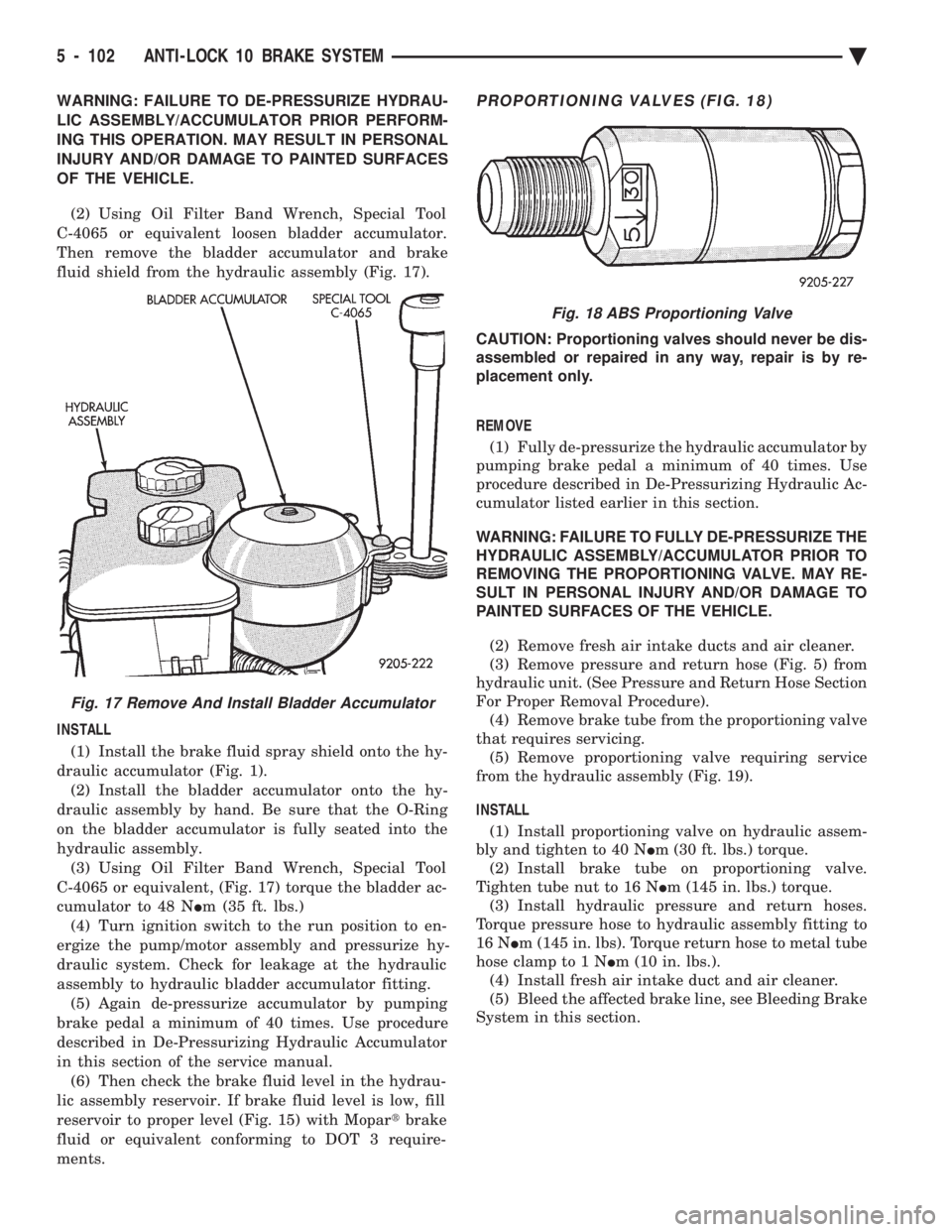
(2) Using Oil Filter Band Wrench, Special Tool
C-4065 or equivalent loosen bladder accumulator.
Then remove the bladder accumulator and brake
fluid shield from the hydraulic assembly (Fig. 17).
INSTALL
(1) Install the brake fluid spray shield onto the hy-
draulic accumulator (Fig. 1). (2) Install the bladder accumulator onto the hy-
draulic assembly by hand. Be sure that the O-Ring
on the bladder accumulator is fully seated into the
hydraulic assembly. (3) Using Oil Filter Band Wrench, Special Tool
C-4065 or equivalent, (Fig. 17) torque the bladder ac-
cumulator to 48 N Im (35 ft. lbs.)
(4) Turn ignition switch to the run position to en-
ergize the pump/motor assembly and pressurize hy-
draulic system. Check for leakage at the hydraulic
assembly to hydraulic bladder accumulator fitting. (5) Again de-pressurize accumulator by pumping
brake pedal a minimum of 40 times. Use procedure
described in De-Pressurizing Hydraulic Accumulator
in this section of the service manual. (6) Then check the brake fluid level in the hydrau-
lic assembly reservoir. If brake fluid level is low, fill
reservoir to proper level (Fig. 15) with Mopar tbrake
fluid or equivalent conforming to DOT 3 require-
ments.PROPORTIONING VALVES (FIG. 18)
CAUTION: Proportioning valves should never be dis-
assembled or repaired in any way, repair is by re-
placement only.
REMOVE (1) Fully de-pressurize the hydraulic accumulator by
pumping brake pedal a minimum of 40 times. Use
procedure described in De-Pressurizing Hydraulic Ac-
cumulator listed earlier in this section.
WARNING: FAILURE TO FULLY DE-PRESSURIZE THE
HYDRAULIC ASSEMBLY/ACCUMULATOR PRIOR TO
REMOVING THE PROPORTIONING VALVE. MAY RE-
SULT IN PERSONAL INJURY AND/OR DAMAGE TO
PAINTED SURFACES OF THE VEHICLE.
(2) Remove fresh air intake ducts and air cleaner.
(3) Remove pressure and return hose (Fig. 5) from
hydraulic unit. (See Pressure and Return Hose Section
For Proper Removal Procedure). (4) Remove brake tube from the proportioning valve
that requires servicing. (5) Remove proportioning valve requiring service
from the hydraulic assembly (Fig. 19).
INSTALL (1) Install proportioning valve on hydraulic assem-
bly and tighten to 40 N Im (30 ft. lbs.) torque.
(2) Install brake tube on proportioning valve.
Tighten tube nut to 16 N Im (145 in. lbs.) torque.
(3) Install hydraulic pressure and return hoses.
Torque pressure hose to hydraulic assembly fitting to
16 N Im (145 in. lbs). Torque return hose to metal tube
hose clamp to 1 N Im (10 in. lbs.).
(4) Install fresh air intake duct and air cleaner.
(5) Bleed the affected brake line, see Bleeding Brake
System in this section.
Fig. 17 Remove And Install Bladder Accumulator
Fig. 18 ABS Proportioning Valve
5 - 102 ANTI-LOCK 10 BRAKE SYSTEM Ä
Page 253 of 2438
ELECTRONIC COMPONENTS
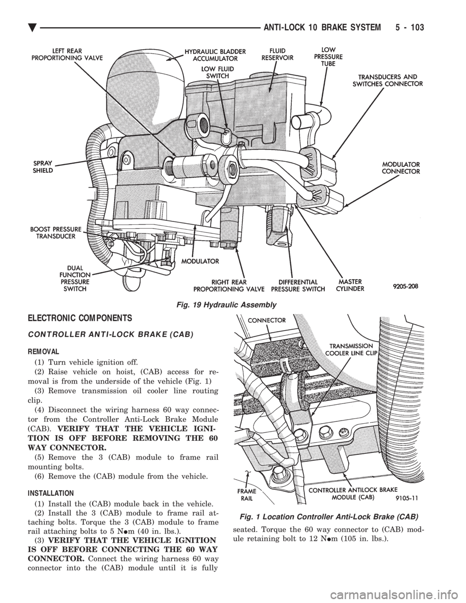
CONTROLLER ANTI-LOCK BRAKE (CAB)
REMOVAL (1) Turn vehicle ignition off.
(2) Raise vehicle on hoist, (CAB) access for re-
moval is from the underside of the vehicle (Fig. 1) (3) Remove transmission oil cooler line routing
clip. (4) Disconnect the wiring harness 60 way connec-
tor from the Controller Anti-Lock Brake Module
(CAB). VERIFY THAT THE VEHICLE IGNI-
TION IS OFF BEFORE REMOVING THE 60
WAY CONNECTOR. (5) Remove the 3 (CAB) module to frame rail
mounting bolts. (6) Remove the (CAB) module from the vehicle.
INSTALLATION (1) Install the (CAB) module back in the vehicle.
(2) Install the 3 (CAB) module to frame rail at-
taching bolts. Torque the 3 (CAB) module to frame
rail attaching bolts to 5 N Im (40 in. lbs.).
(3) VERIFY THAT THE VEHICLE IGNITION
IS OFF BEFORE CONNECTING THE 60 WAY
CONNECTOR. Connect the wiring harness 60 way
connector into the (CAB) module until it is fully seated. Torque the 60 way connector to (CAB) mod-
ule retaining bolt to 12 N Im (105 in. lbs.).
Fig. 19 Hydraulic Assembly
Fig. 1 Location Controller Anti-Lock Brake (CAB)
Ä ANTI-LOCK 10 BRAKE SYSTEM 5 - 103
Page 258 of 2438

CAUTION: Do not insert dual function pressure
switch into hydraulic assembly using the socket
and ratchet. Cross threading of the switch may oc-
cur. (1) Install the dual function pressure switch into
the hydraulic assembly by hand until the O-ring
seals are seated. (2) Using Socket, Special Tool 6607, (Fig. 10)
torque the dual function pressure switch into the hy-
draulic assembly to 12 N Im (9 ft. lbs.).
(3) Connect the wiring harness connectors (Fig. 9)
onto the dual function pressure switch and the boost
pressure transducer. Be sure the locking tabs on the
connectors are fully engaged on the switches. (4) Lower the vehicle.
(5) Turn the ignition switch to the on position and
let the system pressurize. Check for any leaks at the
dual function pressure switch. (6) Fully de-pressurize the hydraulic assembly a
second time. This will purge any air out that may
have entered hydraulic assembly when the switch
was removed. Turn the ignition switch to the on po-
sition and let the system pressurize again. (7) Road test vehicle to insure that the brake sys-
tem is performing correctly.
PRIMARY PRESSURE TRANSDUCER
REMOVE
WARNING: FAILURE TO FULLY DE-PRESSURIZE
THE HYDRAULIC BLADDER ACCUMULATOR PRIOR
TO REMOVING PRIMARY PRESSURE TRANS-
DUCER. WILL RESULT IN PERSONAL INJURY
AND/OR DAMAGE TO PAINTED SURFACES OF THE
VEHICLE.
To remove primary pressure transducer (Fig. 11),
from hydraulic assembly, removal of hydraulic as-
sembly from vehicle is notrequired.
(1) Fully de-pressurize the hydraulic accumulator
by pumping brake pedal a minimum of 40 times. Use
procedure described in De-Pressurizing Hydraulic Ac-
cumulator listed earlier in this section. (2) Remove as much brake fluid as possible from
the brake fluid reservoir, using a syringe or equiva-
lent method. (3) Using oil filter band wrench, Special Tool
C-4065 or equivalent, (Fig. 12) loosen bladder accu-
mulator. Then remove bladder accumulator and
brake fluid spray shield from hydraulic assembly. (4) Remove high pressure banjo fitting (Fig. 13)
from hydraulic assembly. (5) Using needle nose pliers, remove the 3 fluid
reservoir retaining pins from the hydraulic assembly
(Fig. 14). Compress barb on opposite side of retaining
pin, to prevent pin from breaking. CAUTION: Be extremely careful during the following
procedure to avoid damaging or puncturing brake
fluid reservoir during its removal.
(6) Remove brake fluid reservoir from hydraulic
assembly by carefullyprying between reservoir and
hydraulic assembly using a blunt pry bar (Fig. 15).
Use a rocking motion to help disengage reservoir
from grommets while prying. (7) Remove brake fluid level sensor from reservoir
and remove fluid reservoir from vehicle. (8) Remove hydraulic assembly wiring harness
connector from the primary pressure transducer (Fig.
16).
Fig. 11 Primary Pressure Transducer Location On Hydraulic Assembly
Fig. 12 Removing Bladder Accumulator
5 - 108 ANTI-LOCK 10 BRAKE SYSTEM Ä
Page 260 of 2438
(7) Using needle nose pliers, install the 3 brake fluid
reservoir to hydraulic assembly retaining pins (Fig.
14). Be sure retaining pins are fully installed with
barbs extending out past reservoir on opposite
side. (8) Install high pressure hose banjo fitting onto
hydraulic assembly and install banjo fitting attaching
bolt. Torque banjo fitting to hydraulic assembly banjo
bolt to 13 N Im (10 ft. lbs.).
(9) Install brake fluid spray shield onto hydraulic
assembly. Install bladder accumulator into hydraulic
assembly by hand (using care not to cross thread
accumulator) until O-ring seal is fully seated into
hydraulic assembly. (10) Using Oil Filter Band Wrench, Special Tool
C-4065 or equivalent, (Fig. 12) torque bladder accumu-
lator to 48 N Im (35 ft. lbs.).
(11) Fill hydraulic assembly fluid reservoir to the top
of the screen on the filter rainer. Use only fresh clean
brake fluid conforming to DOT 3 requirements, such as
Mopar tor equivalent.
(12) Bleed the brake hydraulic system using proce-
dure shown in Bleeding Brake System in this section of
the service manual.
DIFFERENTIAL PRESSURE SWITCH
REMOVE
WARNING: FAILURE TO FULLY DE-PRESSURIZE THE
HYDRAULIC BLADDER ACCUMULATOR PRIOR TO
REMOVING DIFFERENTIAL PRESSURE SWITCH.
WILL RESULT IN PERSONAL INJURY AND/OR DAM-
AGE TO PAINTED SURFACES OF THE VEHICLE.
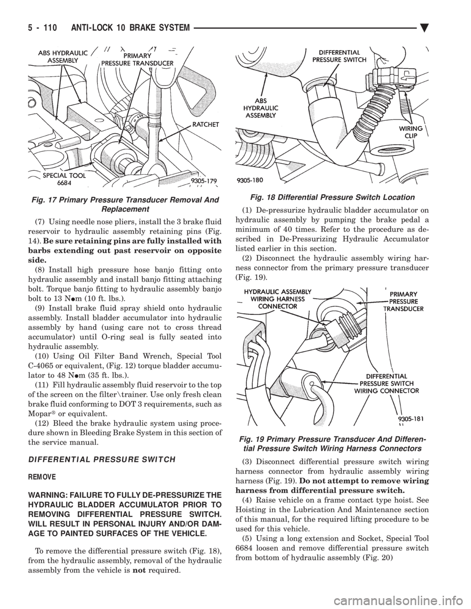
To remove the differential pressure switch (Fig. 18),
from the hydraulic assembly, removal of the hydraulic
assembly from the vehicle is notrequired. (1) De-pressurize hydraulic bladder accumulator on
hydraulic assembly by pumping the brake pedal a
minimum of 40 times. Refer to the procedure as de-
scribed in De-Pressurizing Hydraulic Accumulator
listed earlier in this section. (2) Disconnect the hydraulic assembly wiring har-
ness connector from the primary pressure transducer
(Fig. 19).
(3) Disconnect differential pressure switch wiring
harness connector from hydraulic assembly wiring
harness (Fig. 19). Do not attempt to remove wiring
harness from differential pressure switch. (4) Raise vehicle on a frame contact type hoist. See
Hoisting in the Lubrication And Maintenance section
of this manual, for the required lifting procedure to be
used for this vehicle. (5) Using a long extension and Socket, Special Tool
6684 loosen and remove differential pressure switch
from bottom of hydraulic assembly (Fig. 20)
Fig. 18 Differential Pressure Switch Location
Fig. 19 Primary Pressure Transducer And Differen- tial Pressure Switch Wiring Harness Connectors
Fig. 17 Primary Pressure Transducer Removal And Replacement
5 - 110 ANTI-LOCK 10 BRAKE SYSTEM Ä
Page 270 of 2438
DIAGNOSTIC CONNECTOR
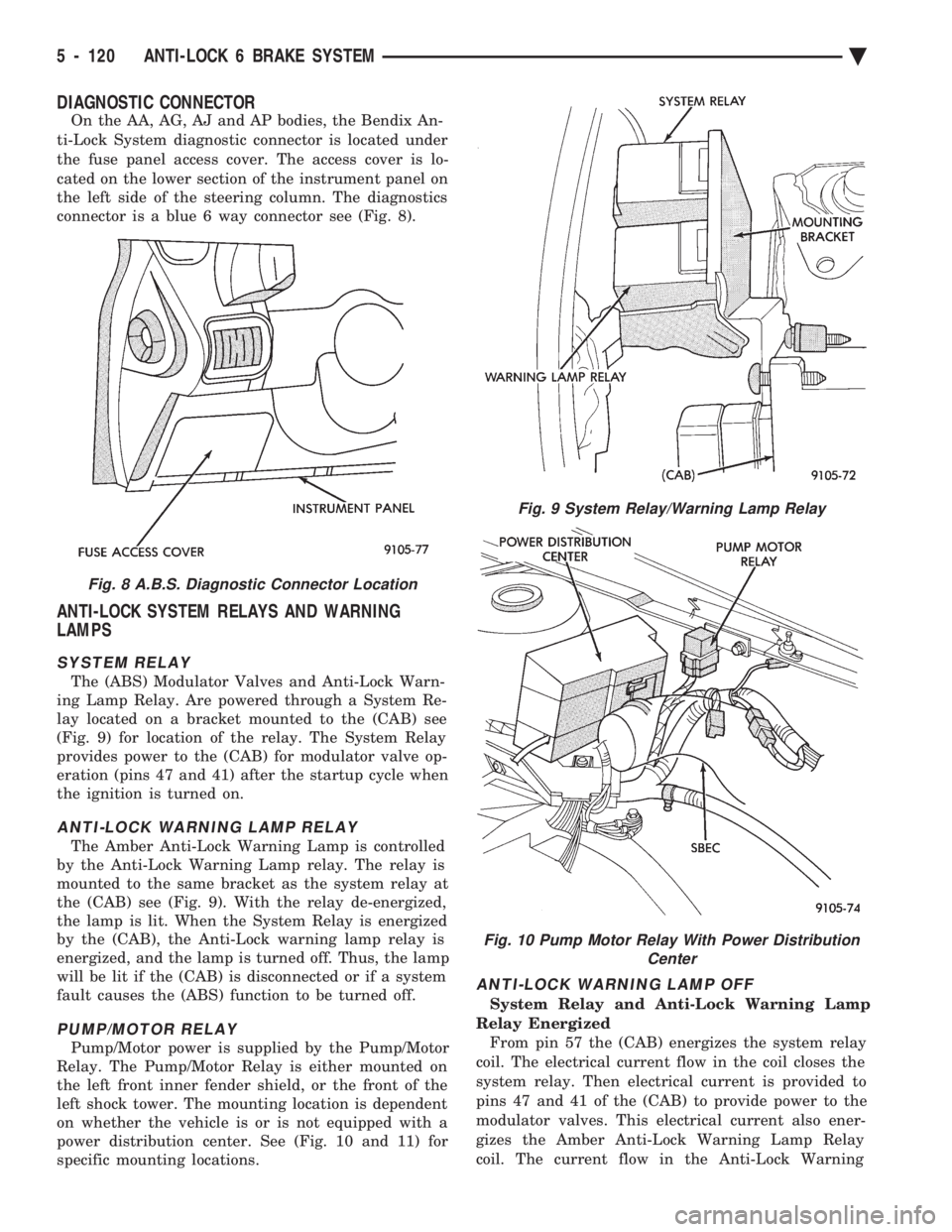
On the AA, AG, AJ and AP bodies, the Bendix An-
ti-Lock System diagnostic connector is located under
the fuse panel access cover. The access cover is lo-
cated on the lower section of the instrument panel on
the left side of the steering column. The diagnostics
connector is a blue 6 way connector see (Fig. 8).
ANTI-LOCK SYSTEM RELAYS AND WARNING
LAMPS
SYSTEM RELAY
The (ABS) Modulator Valves and Anti-Lock Warn-
ing Lamp Relay. Are powered through a System Re-
lay located on a bracket mounted to the (CAB) see
(Fig. 9) for location of the relay. The System Relay
provides power to the (CAB) for modulator valve op-
eration (pins 47 and 41) after the startup cycle when
the ignition is turned on.
ANTI-LOCK WARNING LAMP RELAY
The Amber Anti-Lock Warning Lamp is controlled
by the Anti-Lock Warning Lamp relay. The relay is
mounted to the same bracket as the system relay at
the (CAB) see (Fig. 9). With the relay de-energized,
the lamp is lit. When the System Relay is energized
by the (CAB), the Anti-Lock warning lamp relay is
energized, and the lamp is turned off. Thus, the lamp
will be lit if the (CAB) is disconnected or if a system
fault causes the (ABS) function to be turned off.
PUMP/MOTOR RELAY
Pump/Motor power is supplied by the Pump/Motor
Relay. The Pump/Motor Relay is either mounted on
the left front inner fender shield, or the front of the
left shock tower. The mounting location is dependent
on whether the vehicle is or is not equipped with a
power distribution center. See (Fig. 10 and 11) for
specific mounting locations.
ANTI-LOCK WARNING LAMP OFF
System Relay and Anti-Lock Warning Lamp
Relay Energized From pin 57 the (CAB) energizes the system relay
coil. The electrical current flow in the coil closes the
system relay. Then electrical current is provided to
pins 47 and 41 of the (CAB) to provide power to the
modulator valves. This electrical current also ener-
gizes the Amber Anti-Lock Warning Lamp Relay
coil. The current flow in the Anti-Lock Warning
Fig. 8 A.B.S. Diagnostic Connector Location
Fig. 9 System Relay/Warning Lamp Relay
Fig. 10 Pump Motor Relay With Power Distribution Center
5 - 120 ANTI-LOCK 6 BRAKE SYSTEM Ä
Page 271 of 2438

Lamp Relay opens the Anti-Lock Warning Lamp Re-
lay switch. This breaks the ground path to the Am-
ber Anti-Lock Warning Lamp and the light is turned
off. The (CAB) by itself, also has the ability to turn on
the Amber Anti-Lock Warning Lamp. The (CAB) can
turn on the Amber Anti-Lock Warning Lamp by pro-
viding a ground at pin 15.
ANTI-LOCK WARNING LAMP ON
System Relay and Anti-Lock Warning Lamp
Relay De-Energized. When the Amber Anti-Lock Warning Lamp is on,
there is no electrical current flow from the (CAB) at
pin 57. The System Relay coil is NOT energized. No
electrical current flows to pin 47 and 41 (modulator
valve power), or to the Anti-Lock Warning Lamp Re-
lay coil. Thus, the Amber Anti-Lock Warning Lamp
is not energized. The Amber Anti-Lock Warning Lamp is grounded through the Anti-Lock Warning
Lamp Relay contacts. The Amber Anti-Lock Warning
Lamp is turned on.
HYDRAULIC CIRCUITS AND VALVE OPERATION
Through the following operation descriptions and
diagrams. The function of the various hydraulic con-
trol valves in the ABS system will be described. The
fluid control valves mentioned below, control the flow
of pressurized brake fluid to the wheel brakes during
the different modes of Anti-Lock braking. For explanation purposes we will assume all speed
sensors are sending the same wheel speed informa-
tion, requiring the same hydraulic fluid modulation
at the same rate.
NORMAL BRAKING
ISOLATION VALVES
Open to primary and secondary master cylinder
fluid supply (Fig. 1)
BUILD/DECAY VALVES Closed (Fig. 1)
The brake pedal is applied. The travel of the brake
pedal closes primary and secondary circuits from the
master cylinder fluid supply. Brake fluid from the
primary and secondary circuits flows through the
open isolation valves, through the build/decay valves
to the wheel brakes.
ABS BRAKING-BUILD PRESSURE
ISOLATION VALVES
Closed, isolating wheel brakes from master cylin-
der primary and secondary fluid supply. Through
open build valves (Fig. 2).
BUILD/DECAY VALVES Open (Fig. 2)
Fig. 11 Pump Motor Relay W/O Power Distribution Center
Ä ANTI-LOCK 6 BRAKE SYSTEM 5 - 121
Page 276 of 2438
As soon as the condition goes away, the Anti-Lock
Warning Light is turned off. Although a fault code
will be set in most cases.
BENDIX ABS SYSTEMS DIAGNOSTICS
Bendix Anti-Lock 6 Brake System Diagnostics, be-
yond basic mechanical diagnostics, covered earlier in
this section. Are accomplished by using the DRB II
scan tool. See testing procedures outlined in the Ben-
dix Anti-Lock 6 Diagnostics Manual for the 1992
M.Y. vehicles. Please refer to the above mentioned manual for
any further electronic diagnostics and service proce-
dures that are required on the Bendix Anti-Lock 6
Brake System.
ON-CAR ABS BRAKE SYSTEM SERVICE
GENERAL SERVICE PRECAUTIONS
The following are general cautions which should be
observed when servicing the Anti-Lock brake system
and/or other vehicle systems. Failure to observe
these precautions may result in Anti-Lock Brake
System component damage. If welding work is to be performed on the vehicle,
using an electric arc welder, the (CAB) connector
should be disconnected during the welding operation. The (CAB) connector should never be connected or
disconnected with the ignition switch in the ON po-
sition. Many components of the Anti-Lock Brake System
are not serviceable and must be replaced as an as-
sembly. Do not disassemble any component which is
not designed to be serviced.
CHECKING BRAKE FLUID LEVEL
CAUTION: Only use brake fluid conforming to DOT
3 specifications, such as Mopar or Equivalent. Do
not use any fluid which contains a petroleum base.
Do not use a container which has been used for pe-
troleum based fluids or a container which is wet
with water. Petroleum based fluids will cause swell-
ing and distortion of rubber parts in the hydraulic
brake system. Water will mix with brake fluid, low-
ering the fluid boiling point. Keep all brake fluid
containers capped to prevent contamination. Re-
move the front cap of the master cylinder reservoir
and fill to the bottom of the split ring.
For the specific procedure for the inspection of
brake fluid level and adding of brake to the reser-
voir. Refer to the Service Adjustments Section in this
group of the service manual.
BLEEDING BENDIX ANTI-LOCK 6 BRAKE SYSTEM
The Anti-Lock Brake System must be bled anytime
air is permitted to enter the hydraulic system, due to
disconnection of brake lines, hoses of components. If the Modulator Assembly is removed from the ve-
hicle, both the Base Brake System and the Anti-Lock
Brake System must be bled using the appropriate
procedures. It is important to note that excessive air
in the brake system will cause a soft or spongy feel-
ing brake pedal. During bleeding operations, be sure that the brake
fluid level remains close to the FULL level in the
reservoir. Check the fluid level periodically during
the bleeding procedure and add DOT 3 brake fluid as
required. The Bendix Anti-Lock 6 Brake System must be
bled as two independent braking systems. The non
ABS portion of the brake system is to be bled the
same as any non ABS system. Refer to the Service
Adjustments section in this manual for the proper
bleeding procedure to be used. This brake system can
be either pressure bled or manually bled. The Anti-Lock portion of brake system MUST be
bled separately. This bleeding procedure requires the
use of the DRB II Diagnostic tester and the bleeding
sequence procedure outlined below.
ABS BLEEDING PROCEDURE (FIG. 1)
(1) Assemble and install all brake system compo-
nents on vehicle making sure all hydraulic fluid
lines are installed and properly torqued. (2) Bleed the base brake system. Using the stan-
dard pressure or manual bleeding procedure as out-
lined in the Service Adjustments section of this
service manual. To perform the bleeding procedure on the ABS
unit. The battery and acid shield must be removed
from the vehicle. Reconnect the vehicles battery, to
the vehicles positive and negative battery cables us-
ing jumper cables. This is necessary to allow access
to the 4 bleeder screws located on the top of the Mod-
ulator assembly. (3) Connect the DRB II Diagnostics Tester to the
diagnostics connector. Located behind the Fuse Panel
access cover on the lower section of the dash panel to
the left of the steering column. (It is a blue 6 way
connector). (4) Using the DRB II check to make sure the
(CAB) does not have any fault codes stored. If it does
remove them using the DRB II.
5 - 126 ANTI-LOCK 6 BRAKE SYSTEM Ä