1993 CHEVROLET DYNASTY oil
[x] Cancel search: oilPage 171 of 2438
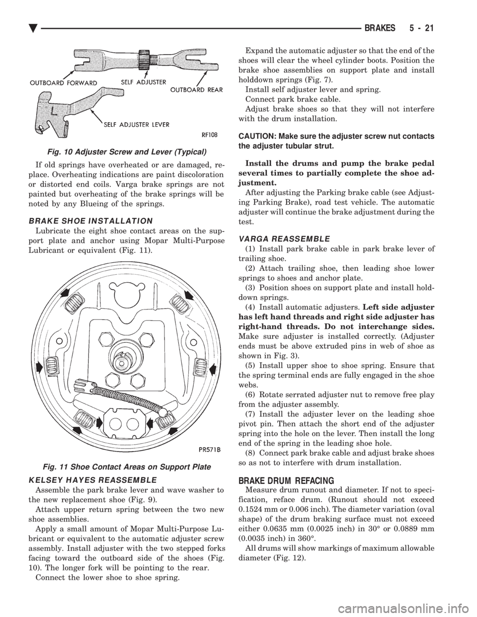
If old springs have overheated or are damaged, re-
place. Overheating indications are paint discoloration
or distorted end coils. Varga brake springs are not
painted but overheating of the brake springs will be
noted by any Blueing of the springs.
BRAKE SHOE INSTALLATION
Lubricate the eight shoe contact areas on the sup-
port plate and anchor using Mopar Multi-Purpose
Lubricant or equivalent (Fig. 11).
KELSEY HAYES REASSEMBLE
Assemble the park brake lever and wave washer to
the new replacement shoe (Fig. 9). Attach upper return spring between the two new
shoe assemblies. Apply a small amount of Mopar Multi-Purpose Lu-
bricant or equivalent to the automatic adjuster screw
assembly. Install adjuster with the two stepped forks
facing toward the outboard side of the shoes (Fig.
10). The longer fork will be pointing to the rear. Connect the lower shoe to shoe spring. Expand the automatic adjuster so that the end of the
shoes will clear the wheel cylinder boots. Position the
brake shoe assemblies on support plate and install
holddown springs (Fig. 7). Install self adjuster lever and spring.
Connect park brake cable.
Adjust brake shoes so that they will not interfere
with the drum installation.
CAUTION: Make sure the adjuster screw nut contacts
the adjuster tubular strut.
Install the drums and pump the brake pedal
several times to partially complete the shoe ad-
justment. After adjusting the Parking brake cable (see Adjust-
ing Parking Brake), road test vehicle. The automatic
adjuster will continue the brake adjustment during the
test.
VARGA REASSEMBLE
(1) Install park brake cable in park brake lever of
trailing shoe. (2) Attach trailing shoe, then leading shoe lower
springs to shoes and anchor plate. (3) Position shoes on support plate and install hold-
down springs. (4) Install automatic adjusters. Left side adjuster
has left hand threads and right side adjuster has
right-hand threads. Do not interchange sides.
Make sure adjuster is installed correctly. (Adjuster
ends must be above extruded pins in web of shoe as
shown in Fig. 3). (5) Install upper shoe to shoe spring. Ensure that
the spring terminal ends are fully engaged in the shoe
webs. (6) Rotate serrated adjuster nut to remove free play
from the adjuster assembly. (7) Install the adjuster lever on the leading shoe
pivot pin. Then attach the short end of the adjuster
spring into the hole on the lever. Then install the long
end of the spring in the leading shoe hole. (8) Connect park brake cable and adjust brake shoes
so as not to interfere with drum installation.
BRAKE DRUM REFACING
Measure drum runout and diameter. If not to speci-
fication, reface drum. (Runout should not exceed
0.1524 mm or 0.006 inch). The diameter variation (oval
shape) of the drum braking surface must not exceed
either 0.0635 mm (0.0025 inch) in 30É or 0.0889 mm
(0.0035 inch) in 360É. All drums will show markings of maximum allowable
diameter (Fig. 12).
Fig. 10 Adjuster Screw and Lever (Typical)
Fig. 11 Shoe Contact Areas on Support Plate
Ä BRAKES 5 - 21
Page 220 of 2438
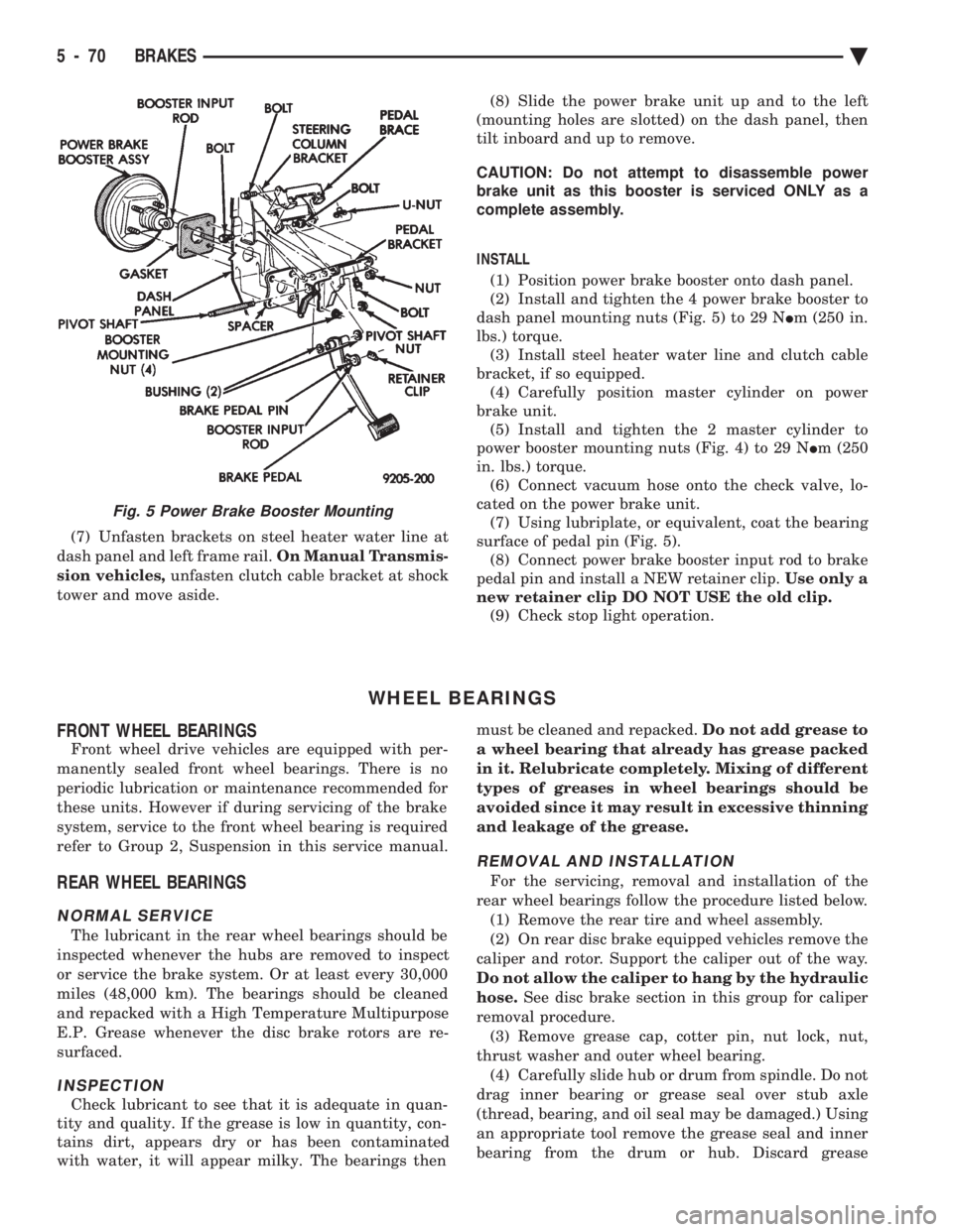
(7) Unfasten brackets on steel heater water line at
dash panel and left frame rail. On Manual Transmis-
sion vehicles, unfasten clutch cable bracket at shock
tower and move aside. (8) Slide the power brake unit up and to the left
(mounting holes are slotted) on the dash panel, then
tilt inboard and up to remove.
CAUTION: Do not attempt to disassemble power
brake unit as this booster is serviced ONLY as a
complete assembly.
INSTALL (1) Position power brake booster onto dash panel.
(2) Install and tighten the 4 power brake booster to
dash panel mounting nuts (Fig. 5) to 29 N Im (250 in.
lbs.) torque. (3) Install steel heater water line and clutch cable
bracket, if so equipped. (4) Carefully position master cylinder on power
brake unit. (5) Install and tighten the 2 master cylinder to
power booster mounting nuts (Fig. 4) to 29 N Im (250
in. lbs.) torque. (6) Connect vacuum hose onto the check valve, lo-
cated on the power brake unit. (7) Using lubriplate, or equivalent, coat the bearing
surface of pedal pin (Fig. 5). (8) Connect power brake booster input rod to brake
pedal pin and install a NEW retainer clip. Use only a
new retainer clip DO NOT USE the old clip. (9) Check stop light operation.
WHEEL BEARINGS
FRONT WHEEL BEARINGS
Front wheel drive vehicles are equipped with per-
manently sealed front wheel bearings. There is no
periodic lubrication or maintenance recommended for
these units. However if during servicing of the brake
system, service to the front wheel bearing is required
refer to Group 2, Suspension in this service manual.
REAR WHEEL BEARINGS
NORMAL SERVICE
The lubricant in the rear wheel bearings should be
inspected whenever the hubs are removed to inspect
or service the brake system. Or at least every 30,000
miles (48,000 km). The bearings should be cleaned
and repacked with a High Temperature Multipurpose
E.P. Grease whenever the disc brake rotors are re-
surfaced.
INSPECTION
Check lubricant to see that it is adequate in quan-
tity and quality. If the grease is low in quantity, con-
tains dirt, appears dry or has been contaminated
with water, it will appear milky. The bearings then must be cleaned and repacked.
Do not add grease to
a wheel bearing that already has grease packed
in it. Relubricate completely. Mixing of different
types of greases in wheel bearings should be
avoided since it may result in excessive thinning
and leakage of the grease.
REMOVAL AND INSTALLATION
For the servicing, removal and installation of the
rear wheel bearings follow the procedure listed below. (1) Remove the rear tire and wheel assembly.
(2) On rear disc brake equipped vehicles remove the
caliper and rotor. Support the caliper out of the way.
Do not allow the caliper to hang by the hydraulic
hose. See disc brake section in this group for caliper
removal procedure. (3) Remove grease cap, cotter pin, nut lock, nut,
thrust washer and outer wheel bearing. (4) Carefully slide hub or drum from spindle. Do not
drag inner bearing or grease seal over stub axle
(thread, bearing, and oil seal may be damaged.) Using
an appropriate tool remove the grease seal and inner
bearing from the drum or hub. Discard grease
Fig. 5 Power Brake Booster Mounting
5 - 70 BRAKES Ä
Page 221 of 2438
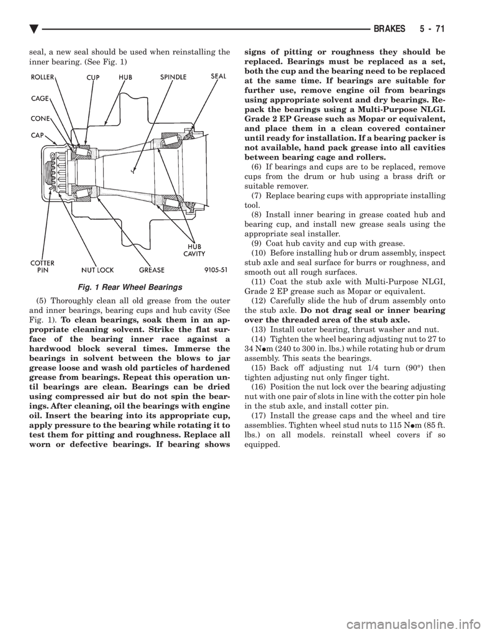
seal, a new seal should be used when reinstalling the
inner bearing. (See Fig. 1) (5) Thoroughly clean all old grease from the outer
and inner bearings, bearing cups and hub cavity (See
Fig. 1). To clean bearings, soak them in an ap-
propriate cleaning solvent. Strike the flat sur-
face of the bearing inner race against a
hardwood block several times. Immerse the
bearings in solvent between the blows to jar
grease loose and wash old particles of hardened
grease from bearings. Repeat this operation un-
til bearings are clean. Bearings can be dried
using compressed air but do not spin the bear-
ings. After cleaning, oil the bearings with engine
oil. Insert the bearing into its appropriate cup,
apply pressure to the bearing while rotating it to
test them for pitting and roughness. Replace all
worn or defective bearings. If bearing shows signs of pitting or roughness they should be
replaced. Bearings must be replaced as a set,
both the cup and the bearing need to be replaced
at the same time. If bearings are suitable for
further use, remove engine oil from bearings
using appropriate solvent and dry bearings. Re-
pack the bearings using a Multi-Purpose NLGI.
Grade 2 EP Grease such as Mopar or equivalent,
and place them in a clean covered container
until ready for installation. If a bearing packer is
not available, hand pack grease into all cavities
between bearing cage and rollers. (6) If bearings and cups are to be replaced, remove
cups from the drum or hub using a brass drift or
suitable remover. (7) Replace bearing cups with appropriate installing
tool. (8) Install inner bearing in grease coated hub and
bearing cup, and install new grease seals using the
appropriate seal installer. (9) Coat hub cavity and cup with grease.
(10) Before installing hub or drum assembly, inspect
stub axle and seal surface for burrs or roughness, and
smooth out all rough surfaces. (11) Coat the stub axle with Multi-Purpose NLGI,
Grade 2 EP grease such as Mopar or equivalent. (12) Carefully slide the hub of drum assembly onto
the stub axle. Do not drag seal or inner bearing
over the threaded area of the stub axle. (13) Install outer bearing, thrust washer and nut.
(14) Tighten the wheel bearing adjusting nut to 27 to
34 N Im (240 to 300 in. lbs.) while rotating hub or drum
assembly. This seats the bearings. (15) Back off adjusting nut 1/4 turn (90É) then
tighten adjusting nut only finger tight. (16) Position the nut lock over the bearing adjusting
nut with one pair of slots in line with the cotter pin hole
in the stub axle, and install cotter pin. (17) Install the grease caps and the wheel and tire
assemblies. Tighten wheel stud nuts to 115 N Im (85 ft.
lbs.) on all models. reinstall wheel covers if so
equipped.
Fig. 1 Rear Wheel Bearings
Ä BRAKES 5 - 71
Page 227 of 2438
circuits are hydraulically isolated so a leak or mal-
function in one circuit will allow continued braking
ability in the other.When force is applied to the brake pedal, the input
pushrod applies force to the boost control valve. As
the boost control valve is moved, it allows the pres-
surized fluid from the accumulator to flow into the
master cylinder booster chamber. The pressure gen-
erated in the booster chamber is directly propor-
tioned to the brake pedal force exerted by the driver.
This pressure in the booster servo in turn applies
pressure to the primary master cylinder piston that
in turn applies pressure to the secondary master cyl-
inder piston. The pressure generated in the primary
and secondary circuits are used to apply the brakes
during normal braking.
WARNING: THE HYDRAULIC ACCUMULATORS
CONTAIN BRAKE FLUID AND NITROGEN GAS AT
HIGH PRESSURE. CERTAIN PORTIONS OF THE
BRAKE SYSTEM ALSO CONTAIN BRAKE FLUID AT
HIGH PRESSURE. REMOVAL OR DISASSEMBLY
MAY RESULT IN PERSONAL INJURY AND IM-
PROPER SYSTEM OPERATION. REFER TO THE AP-
PROPRIATE SERVICE MANUAL FOR PROPER
SERVICE PROCEDURES.
HYDRAULIC BLADDER ACCUMULATOR
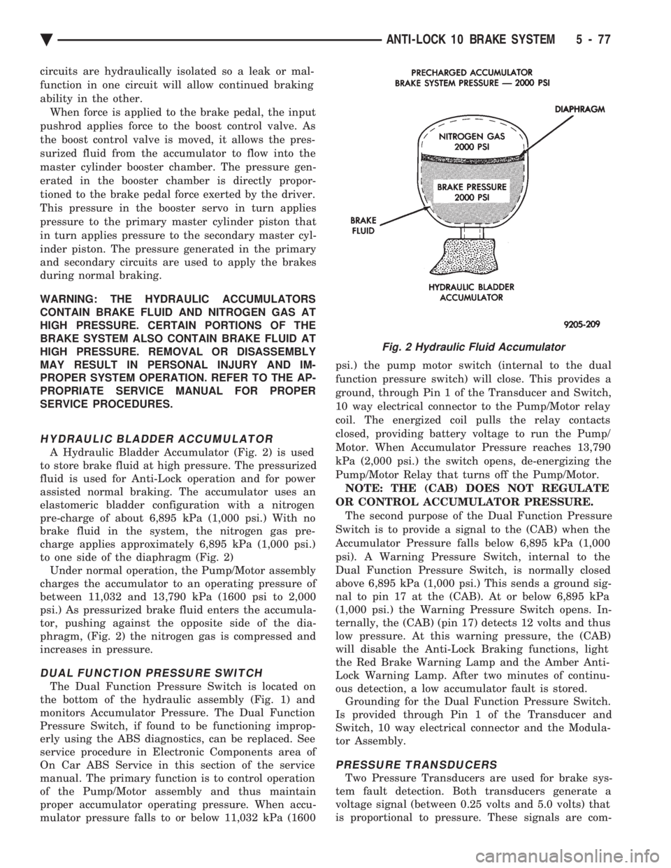
A Hydraulic Bladder Accumulator (Fig. 2) is used
to store brake fluid at high pressure. The pressurized
fluid is used for Anti-Lock operation and for power
assisted normal braking. The accumulator uses an
elastomeric bladder configuration with a nitrogen
pre-charge of about 6,895 kPa (1,000 psi.) With no
brake fluid in the system, the nitrogen gas pre-
charge applies approximately 6,895 kPa (1,000 psi.)
to one side of the diaphragm (Fig. 2) Under normal operation, the Pump/Motor assembly
charges the accumulator to an operating pressure of
between 11,032 and 13,790 kPa (1600 psi to 2,000
psi.) As pressurized brake fluid enters the accumula-
tor, pushing against the opposite side of the dia-
phragm, (Fig. 2) the nitrogen gas is compressed and
increases in pressure.
DUAL FUNCTION PRESSURE SWITCH
The Dual Function Pressure Switch is located on
the bottom of the hydraulic assembly (Fig. 1) and
monitors Accumulator Pressure. The Dual Function
Pressure Switch, if found to be functioning improp-
erly using the ABS diagnostics, can be replaced. See
service procedure in Electronic Components area of
On Car ABS Service in this section of the service
manual. The primary function is to control operation
of the Pump/Motor assembly and thus maintain
proper accumulator operating pressure. When accu-
mulator pressure falls to or below 11,032 kPa (1600 psi.) the pump motor switch (internal to the dual
function pressure switch) will close. This provides a
ground, through Pin 1 of the Transducer and Switch,
10 way electrical connector to the Pump/Motor relay
coil. The energized coil pulls the relay contacts
closed, providing battery voltage to run the Pump/
Motor. When Accumulator Pressure reaches 13,790
kPa (2,000 psi.) the switch opens, de-energizing the
Pump/Motor Relay that turns off the Pump/Motor. NOTE: THE (CAB) DOES NOT REGULATE
OR CONTROL ACCUMULATOR PRESSURE. The second purpose of the Dual Function Pressure
Switch is to provide a signal to the (CAB) when the
Accumulator Pressure falls below 6,895 kPa (1,000
psi). A Warning Pressure Switch, internal to the
Dual Function Pressure Switch, is normally closed
above 6,895 kPa (1,000 psi.) This sends a ground sig-
nal to pin 17 at the (CAB). At or below 6,895 kPa
(1,000 psi.) the Warning Pressure Switch opens. In-
ternally, the (CAB) (pin 17) detects 12 volts and thus
low pressure. At this warning pressure, the (CAB)
will disable the Anti-Lock Braking functions, light
the Red Brake Warning Lamp and the Amber Anti-
Lock Warning Lamp. After two minutes of continu-
ous detection, a low accumulator fault is stored. Grounding for the Dual Function Pressure Switch.
Is provided through Pin 1 of the Transducer and
Switch, 10 way electrical connector and the Modula-
tor Assembly.
PRESSURE TRANSDUCERS
Two Pressure Transducers are used for brake sys-
tem fault detection. Both transducers generate a
voltage signal (between 0.25 volts and 5.0 volts) that
is proportional to pressure. These signals are com-
Fig. 2 Hydraulic Fluid Accumulator
Ä ANTI-LOCK 10 BRAKE SYSTEM 5 - 77
Page 232 of 2438

The primary functions of the (CAB) are:
² (1) Detect wheel locking tendencies.
² (2) Control fluid modulation to the brakes while in
Anti-Lock mode.
² (3) Monitor the system for proper operation.
² (4) Provide communication to the DRB II while in
diagnostic mode. The (CAB) continuously monitors the speed of each
wheel, through the signals generated at the Wheel
Speed Sensors, to determine if any wheel is begin-
ning to lock. When a wheel locking tendency is de-
tected, the (CAB) will isolate the master cylinder
from the wheel brakes. This is done by activating the
Isolation Valves. The (CAB) then commands the ap-
propriate Build or Decay valves to modulate brake
fluid pressure in some or all of the hydraulic circuits.
The fluid used for modulation comes from the booster
servo circuit. The (CAB) continues to control pres-
sure in individual hydraulic circuits until a locking
tendency is no longer present. The (ABS) system is constantly monitored by the
(CAB) for proper operation. If the (CAB) detects a
fault, it can disable the Anti-Lock braking function.
Depending on the fault, the (CAB) will light one or
both of the brake warning lamps. The (CAB) contains a System Diagnostic Program
which triggers the brake system warning lamps
when a system fault is detected. Faults are stored in
a diagnostic program memory. There are 19 fault
codes that may be stored in the (CAB) and displayed
through the DRB II. These fault codes will remain in
the (CAB) memory even after the ignition has been
turned off. These fault codes will remain in memory
until they are cleared with the DRB II, or automati-
cally erased from the memory after (50) ignition
switch on/off cycles.
CONTROLLER ANTI-LOCK BRAKE (INPUTS)
² Four wheel speed sensors.
² Boost pressure transducer.
² Primary pressure transducer.
² Low fluid level switch.
² Differential pressure switch.
² Parking brake switch.
² Dual function pressure switch (warning pressure
only)
² Stop lamp switch.
² Ignition switch.
² System relay voltage.
² Ground.
² Low Accumulator
CONTROLLER ANTI-LOCK BRAKE (OUTPUTS)
²Ten modulator valves-3 decay, 3 build and 4 isola-
tion.
² Red Brake warning lamp.
² Amber Anti-Lock Warning Lamp.
² System relay actuation. ²
Diagnostic communication.
ABS SYSTEM DIAGNOSTIC CONNECTOR
The Bendix Anti-Lock system diagnostic connector
is located under the lower dash panel or in the area
of the fuse box (Fig. 8). The fuse box is located be-
hind the access panel that is on the bottom portion of
the dash panel, left of the steering column. The diag-
nostics connector is a blue 6 way connector.
ANTI-LOCK SYSTEM RELAYS AND WARNING
LAMPS
PUMP/MOTOR RELAY
Pump/Motor power is supplied by the Pump/Motor
Relay. The Pump/Motor relay is located inside the
Power Distribution Center (PDC). The relay coil is
energized by a ground from the Dual Function Pres-
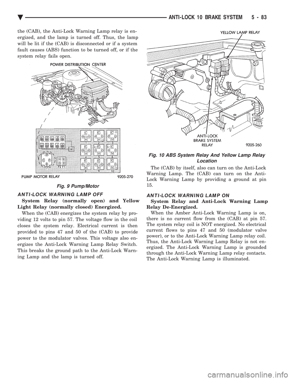
sure Switch. See (Fig. 9) for the location of the pump/
motor relay in the (PDC).
SYSTEM RELAY
The (ABS) Modulator Valves and Anti-Lock Warn-
ing Lamp Relay are controlled through a System Re-
lay. The System relay is located on the top left inner
fender behind the headlight (Fig. 10). The system re-
lay provides power to the (CAB) for modulator valve
operation (pins 47 and 50) after the start-up cycle
when the ignition is turned on.
ANTI-LOCK WARNING LAMP RELAY
The Anti-Lock Warning Lamp is controlled by the
Yellow Light Relay. See (Fig. 10) for location behind
the left headlight. With the relay de-energized, the
lamp is lit. When the system relay is energized by
Fig. 8 A.B.S. Diagnostic Connector Location
5 - 82 ANTI-LOCK 10 BRAKE SYSTEM Ä
Page 233 of 2438
the (CAB), the Anti-Lock Warning Lamp relay is en-
ergized, and the lamp is turned off. Thus, the lamp
will be lit if the (CAB) is disconnected or if a system
fault causes (ABS) function to be turned off, or if the
system relay fails open.
ANTI-LOCK WARNING LAMP OFF
System Relay (normally open) and Yellow
Light Relay (normally closed) Energized. When the (CAB) energizes the system relay by pro-
viding 12 volts to pin 57. The voltage flow in the coil
closes the system relay. Electrical current is then
provided to pins 47 and 50 of the (CAB) to provide
power to the modulator valves. This voltage also en-
ergizes the Anti-Lock Warning Lamp Relay Switch.
This breaks the ground path to the Anti-Lock Warn-
ing Lamp and the lamp is turned off. The (CAB) by itself, also can turn on the Anti-Lock
Warning Lamp. The (CAB) can turn on the Anti-
Lock Warning Lamp by providing a ground at pin
15.
ANTI-LOCK WARNING LAMP ON
System Relay and Anti-Lock Warning Lamp
Relay De-Energized. When the Amber Anti-Lock Warning Lamp is on,
there is no current flow from the (CAB) at pin 57.
The system relay coil is NOT energized. No electrical
current flows to pins 47 and 50 (modulator valve
power), or to the Anti-Lock Warning Lamp relay coil.
Thus, the Anti-Lock Warning Lamp Relay is not en-
ergized. The Anti-Lock Warning Lamp is grounded
through the Anti-Lock Warning Lamp relay contacts.
The Anti-Lock Warning Lamp is illuminated.
Fig. 9 Pump/Motor
Fig. 10 ABS System Relay And Yellow Lamp Relay Location
Ä ANTI-LOCK 10 BRAKE SYSTEM 5 - 83
Page 243 of 2438
DRIVE-OFF CYCLE
The DRIVE-OFF CYCLE takes place when the ve-
hicle reaches about 3 miles per hour the first time af-
ter an ignition reset. During this test, the modulator
solenoid valves are activated briefly to test their
function. The DRIVE-OFF CYCLE will be bypassed
if you drive-off with the service brake pedal de-
pressed.
LATCHING VERSUS NON-LATCHING FAULTS
Some faults detected by the (CAB) are latching.
The fault is latched and (ABS) function is disabled
until the ignition switch is reset (turned OFF/ON).
Thus (ABS) function is disabled even if the original
fault has disappeared during the ignition cycle in
which it occurred. Other faults are non-latching; any
warning lights that are turned on are only on as long
as the fault condition exists. As soon as the condition
goes away. The Amber Anti-Lock Warning Light is
turned off. Although a fault code will be set in most
cases. (Example:low accumulator fault will not be
stored for a time of 2 minutes after the fault is de-
tected).
BENDIX ABS SYSTEMS DIAGNOSTICS
The Bendix Anti-Lock 10 Brake System diagnos-
tics. Beyond the basic mechanical diagnostics, sys-
tems and components covered earlier in this section,
is accomplished by using the DRB II diagnostic
tester. See testing procedures outlined in the Bendix
Anti-Lock 10 Diagnostics Manual for the 1993 M.Y. Please reference the above mentioned manual. For
any further diagnostic service procedures that are re-
quired on the Bendix Anti-Lock 10 Brake System, re-
quiring the use of the DRB II diagnostic tester.
ON CAR HYDRAULIC ABS COMPONENT SERVICE
WARNING: FAILURE TO FULLY DE-PRESSURIZE
THE HYDRAULIC ACCUMULATOR BEFORE PER-
FORMING HYDRAULIC SYSTEM SERVICE OPERA-
TIONS. COULD RESULT IN INJURY TO SERVICE
PERSONNEL AND OR DAMAGE TO PAINTED SUR-
FACES. SEE SECTION 2 FOR ADDITIONAL WARN-
INGS AND CAUTIONS.
GENERAL SERVICE PRECAUTIONS
The following are general precautions that should
be observed when servicing the Anti-Lock Brake Sys-
tem and/or other vehicle systems. Failure to observe
these precautions may result in Anti-Lock brake sys-
tem damage. If welding work is to be performed on the vehicle,
using an electric arc welder, the (CAB) connector
should be disconnected during the welding operation. The (CAB) or hydraulic assembly connector should
never be connected or disconnected with the ignition
switch in the ONposition.
Many components of the Anti-Lock brake system are
not serviceable and must be replaced as an assembly.
Do not attempt to disassemble any component
that is not designed to be a serviced component.
DE-PRESSURIZING HYDRAULIC ACCUMULA- TOR
The pump/motor assembly will keep the hydraulic
accumulator charged to approximately 11,032 and
13,790 kPa (1600 and 2000 psi) any time that the
ignition is in the ON position. The pump/motor assem-
bly cannot run if the ignition is off or if either battery
cable is disconnected. Unless otherwise specified, the hydraulic accumula-
tor should be de-pressurized before disassembling any
portion of the hydraulic system. The following proce-
dure should be used to relieve the pressure in the
hydraulic accumulator: (1) With ignition off, or either battery cable discon-
nected, pump the brake pedal a minimum of 40 times,
using approximately 222 N (50 lbs.) pedal force. A
noticeable change in pedal feel will occur, when the
accumulator is discharged. (2) When a definite increase in pedal effort is felt,
pump pedal a few additional times. This will insure
removal of all hydraulic pressure from the brake sys-
tem.
CHECKING BRAKE FLUID LEVEL
CAUTION: Use only brake fluid conforming to DOT 3
specifications such as Mopar Tor Equivalent. Do not
use any fluid in the brake hydraulic system, which
contains a petroleum base. Do not use a container
which has been used for petroleum based fluids or a
container that is wet with water. Petroleum based
fluids will cause swelling and distortion of rubber
parts in the hydraulic brake system and water will mix
with brake fluid, lowering the fluid boiling point. Keep
all brake fluid containers tightly capped to prevent
contamination.
The hydraulic assembly is equipped with a plastic
fluid reservoir, with a filter/strainer located in the filler
neck of each reservoir section. The Anti-Lock brake system requires that the hy-
draulic accumulator be de-pressurized when checking
the fluid level. To check the brake fluid level, the
following procedure should be used: (1) With the ignition off, de-pressurize the hydraulic
accumulator by applying the brake pedal approxi-
mately 40 times, using a pedal force of approximately
220 N (50 lbs.). A noticeable change in pedal feel will
occur when the accumulator is de-
Ä ANTI-LOCK 10 BRAKE SYSTEM 5 - 93
Page 249 of 2438
(7) Install high pressure hose to hydraulic assem-
bly (Fig. 7). Tighten the hose, to hydraulic assembly
fitting to 16 N Im (145 in. lbs)
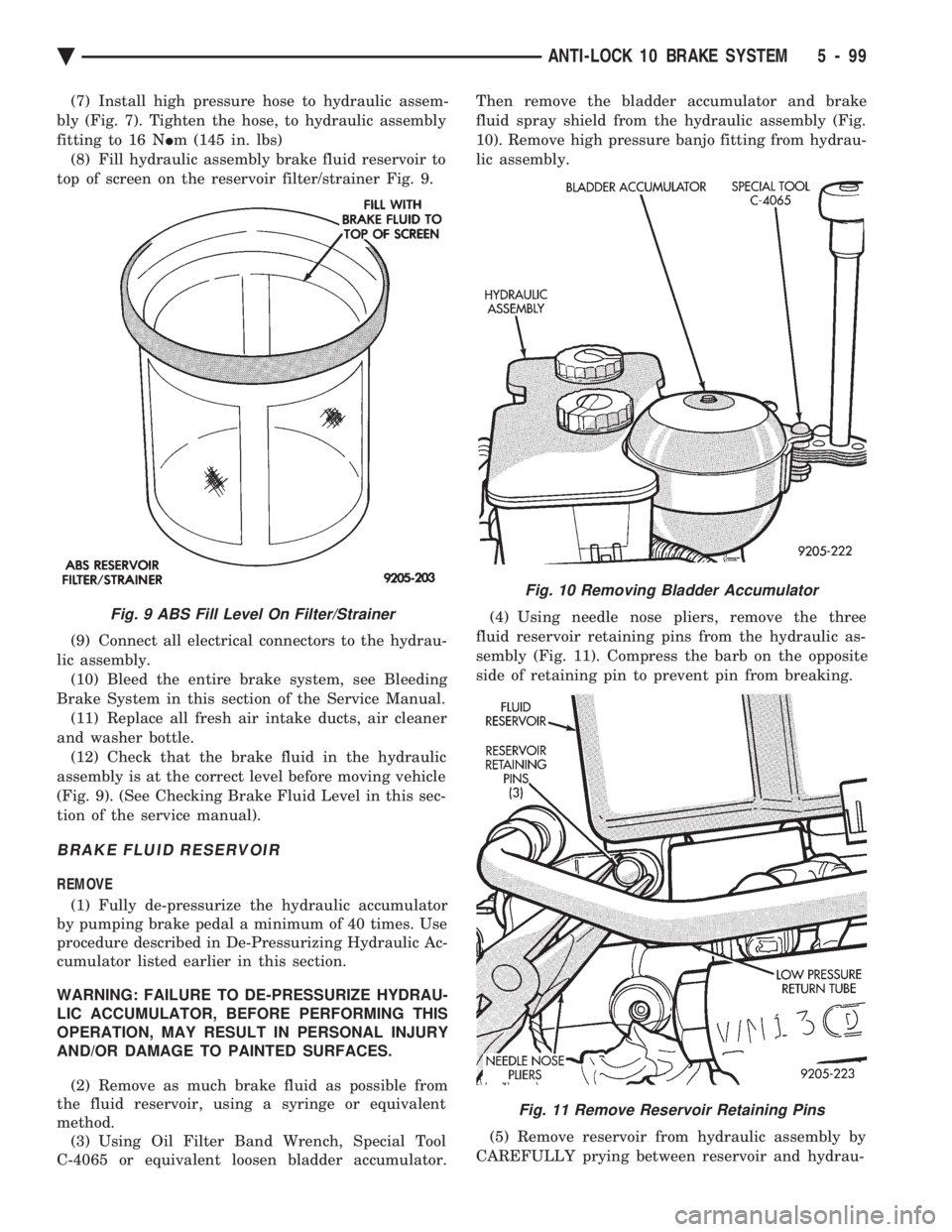
(8) Fill hydraulic assembly brake fluid reservoir to
top of screen on the reservoir filter/strainer Fig. 9.
(9) Connect all electrical connectors to the hydrau-
lic assembly. (10) Bleed the entire brake system, see Bleeding
Brake System in this section of the Service Manual. (11) Replace all fresh air intake ducts, air cleaner
and washer bottle. (12) Check that the brake fluid in the hydraulic
assembly is at the correct level before moving vehicle
(Fig. 9). (See Checking Brake Fluid Level in this sec-
tion of the service manual).
BRAKE FLUID RESERVOIR
REMOVE
(1) Fully de-pressurize the hydraulic accumulator
by pumping brake pedal a minimum of 40 times. Use
procedure described in De-Pressurizing Hydraulic Ac-
cumulator listed earlier in this section.
WARNING: FAILURE TO DE-PRESSURIZE HYDRAU-
LIC ACCUMULATOR, BEFORE PERFORMING THIS
OPERATION, MAY RESULT IN PERSONAL INJURY
AND/OR DAMAGE TO PAINTED SURFACES.
(2) Remove as much brake fluid as possible from
the fluid reservoir, using a syringe or equivalent
method. (3) Using Oil Filter Band Wrench, Special Tool
C-4065 or equivalent loosen bladder accumulator. Then remove the bladder accumulator and brake
fluid spray shield from the hydraulic assembly (Fig.
10). Remove high pressure banjo fitting from hydrau-
lic assembly.
(4) Using needle nose pliers, remove the three
fluid reservoir retaining pins from the hydraulic as-
sembly (Fig. 11). Compress the barb on the opposite
side of retaining pin to prevent pin from breaking.
(5) Remove reservoir from hydraulic assembly by
CAREFULLY prying between reservoir and hydrau-
Fig. 9 ABS Fill Level On Filter/Strainer
Fig. 10 Removing Bladder Accumulator
Fig. 11 Remove Reservoir Retaining Pins
Ä ANTI-LOCK 10 BRAKE SYSTEM 5 - 99