1993 CHEVROLET DYNASTY oil
[x] Cancel search: oilPage 63 of 2438
FRONT SUSPENSION SERVICE PROCEDURES INDEX
page page
Ball Joints .............................. 13
Hub and Bearing Assembly ................. 20
Knuckle (Front Suspension) ................. 16
Lower Control Arm ....................... 10
Lower Control Arm Pivot Bushings ........... 11 Shock Absorbers (Strut Damper)
............. 10
Strut Damper Assembly ..................... 7
Suspension Coil Springs .................... 9
Sway Bar .............................. 14
Wheel Alignment .......................... 5
WHEEL ALIGNMENT
Front wheel alignment is the proper adjustment of
all interrelated front suspension angles. These angles
are what affects the running and steering of the
front wheels of the vehicle. The method of checking front alignment will vary
depending on the type of equipment being used. The
instructions furnished by the manufacturer of the
equipment should always be followed. With the ex-
ception that the alignment specifications recom-
mended by Chrysler Corporation be used. There are six basic factors which are the founda-
tion to front wheel alignment. These are height,
caster, camber, toe-in, steering axis inclination and
toe-out on turns. Of the six basic factors only camber
and toe in are mechanically adjustable (Fig. 1)
CAUTION: Do not attempt to modify any suspen-
sion or steering components by heating or bending
of the component.
Wheel alignment adjustments and checks should be
made in the following sequence. (1) Camber
(2) Toe
Camber is the number of degrees the top of the
wheel is tilted inward or outward from true vertical.
Inward tilt is negative camber. Outward tilt is posi-
tive camber. Excessive camber is a tire wear factor: negative
camber causes wear on the inside of the tire, while
positive camber causes wear to the outside. Toe
is measured in degrees or inches and is the
distance the front edges of the tires are closer (or far-
ther apart) than the rear edges. See Front Wheel
Drive Specifications for Toesettings.
PRE-ALIGNMENT
Before any attempt is made to change or correct
the wheel alignment factors. The following inspection
and necessary corrections must be made on those
parts which influence the steering of the vehicle. (1) Check and inflate tires to recommended pres-
sure. All tires should be the same size and in good
condition and have approximately the same wear.
Note type of tread wear which will aid in diagnosing,
see Wheels and Tires, Group 22. (2) Check front wheel and tire assembly for radial
runout. (3) Inspect lower ball joints and all steering link-
age for looseness. (4) Check for broken or sagged front and rear
springs. Front suspension must only be checked after the
vehicle has had the following checked or adjusted.
Tires set to recommended pressures, full tank of fuel,
no passenger or luggage compartment load and is on
a level floor or alignment rack. Just prior to each alignment reading. The vehicle
should be bounced (rear first, then front) by grasping
bumper at center and jouncing each end an equal
number of times. Always release bumpers at bottom
of down cycle.
Ä SUSPENSION AND DRIVESHAFTS 2 - 5
Page 66 of 2438
INSPECTION
Inspect for evidence of fluid running from the up-
per end of the reservoir. (Actual leakage will be a
stream of fluid running down the side and dripping
off lower end of unit). A slight amount of seepage be-
tween the strut rod and strut shaft seal is not un-
usual and does not affect performance of the strut
assembly.
INSTALLATION
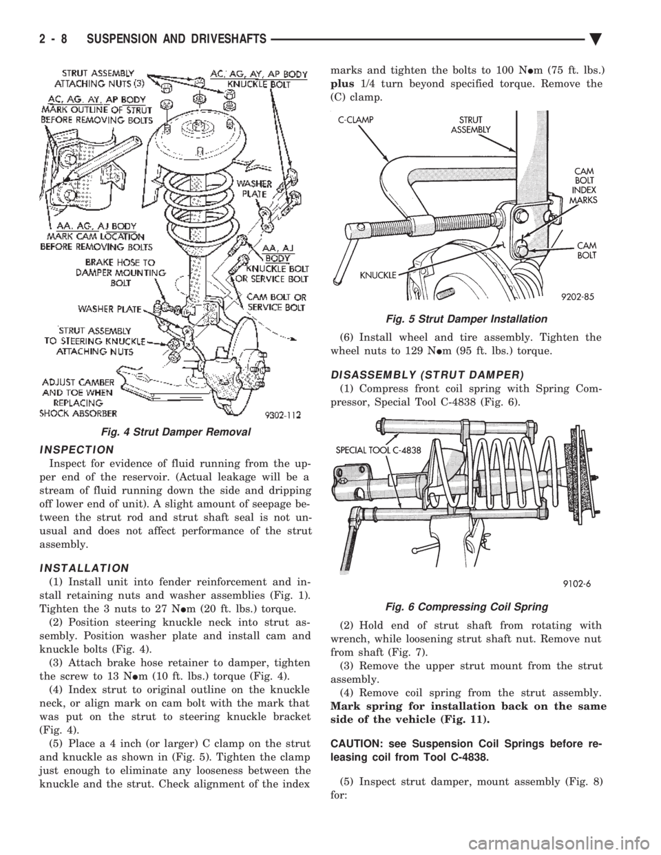
(1) Install unit into fender reinforcement and in-
stall retaining nuts and washer assemblies (Fig. 1).
Tighten the 3 nuts to 27 N Im (20 ft. lbs.) torque.
(2) Position steering knuckle neck into strut as-
sembly. Position washer plate and install cam and
knuckle bolts (Fig. 4). (3) Attach brake hose retainer to damper, tighten
the screw to 13 N Im (10 ft. lbs.) torque (Fig. 4).
(4) Index strut to original outline on the knuckle
neck, or align mark on cam bolt with the mark that
was put on the strut to steering knuckle bracket
(Fig. 4). (5) Plac e a 4 inch (or larger) C clamp on the strut
and knuckle as shown in (Fig. 5). Tighten the clamp
just enough to eliminate any looseness between the
knuckle and the strut. Check alignment of the index marks and tighten the bolts to 100 N
Im (75 ft. lbs.)
plus 1/4 turn beyond specified torque. Remove the
(C) clamp.
(6) Install wheel and tire assembly. Tighten the
wheel nuts to 129 N Im (95 ft. lbs.) torque.
DISASSEMBLY (STRUT DAMPER)
(1) Compress front coil spring with Spring Com-
pressor, Special Tool C-4838 (Fig. 6).
(2) Hold end of strut shaft from rotating with
wrench, while loosening strut shaft nut. Remove nut
from shaft (Fig. 7). (3) Remove the upper strut mount from the strut
assembly. (4) Remove coil spring from the strut assembly.
Mark spring for installation back on the same
side of the vehicle (Fig. 11).
CAUTION: see Suspension Coil Springs before re-
leasing coil from Tool C-4838.
(5) Inspect strut damper, mount assembly (Fig. 8)
for:
Fig. 4 Strut Damper Removal
Fig. 5 Strut Damper Installation
Fig. 6 Compressing Coil Spring
2 - 8 SUSPENSION AND DRIVESHAFTS Ä
Page 67 of 2438
(a) Severe deterioration of rubber isolator; re-
tainers for cracks and distortion and bond failure of
retainers and rubber isolators. (b) Bearings for binding.
(c) Shock Absorber for flat spots over full stroke
also see, Shock Absorbers, (strut damper).
ASSEMBLE (STRUT DAMPER)
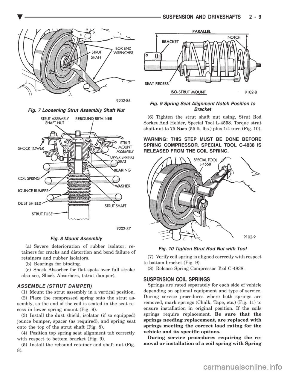
(1) Mount the strut assembly in a vertical position.
(2) Place the compressed spring onto the strut as-
sembly, so the end of the coil is seated in the seat re-
cess in lower spring mount (Fig. 9). (3) Install the dust shield, isolator (if so equipped)
jounce bumper, spacer (as required), and spring seat
onto the top of the strut shaft (Fig. 8). (4) Position top spring seat alignment tab correctly
with respect to bottom bracket (Fig. 9). (5) Install the rebound retainer and shaft nut (Fig.
8). (6) Tighten the strut shaft nut using, Strut Rod
Socket And Holder, Special Tool L-4558. Torque strut
shaft nut to 75 N Im (55 ft. lbs.) plus 1/4 turn (Fig. 10).
WARNING: THIS STEP MUST BE DONE BEFORE
SPRING COMPRESSOR, SPECIAL TOOL C-4838 IS
RELEASED FROM THE COIL SPRING.
(7) Verify coil spring is aligned correctly with respect
to bottom bracket (Fig. 9). (8) Release Spring Compressor Tool C-4838.
SUSPENSION COIL SPRINGS
Springs are rated separately for each side of vehicle
depending on optional equipment and type of service.
During service procedures where both springs are
removed, mark springs (Chalk, Tape, etc.) (Fig. 11) to
ensure installation in original position. If the coils
springs require replacement. Be sure that the
springs needing replacement, are replaced with
springs meeting the correct load rating for the
vehicle and its specific options. During service procedures requiring the re-
moval or installation of a coil spring with Spring
Fig. 7 Loosening Strut Assembly Shaft Nut
Fig. 8 Mount Assembly
Fig. 9 Spring Seat Alignment Notch Position to Bracket
Fig. 10 Tighten Strut Rod Nut with Tool
Ä SUSPENSION AND DRIVESHAFTS 2 - 9
Page 68 of 2438
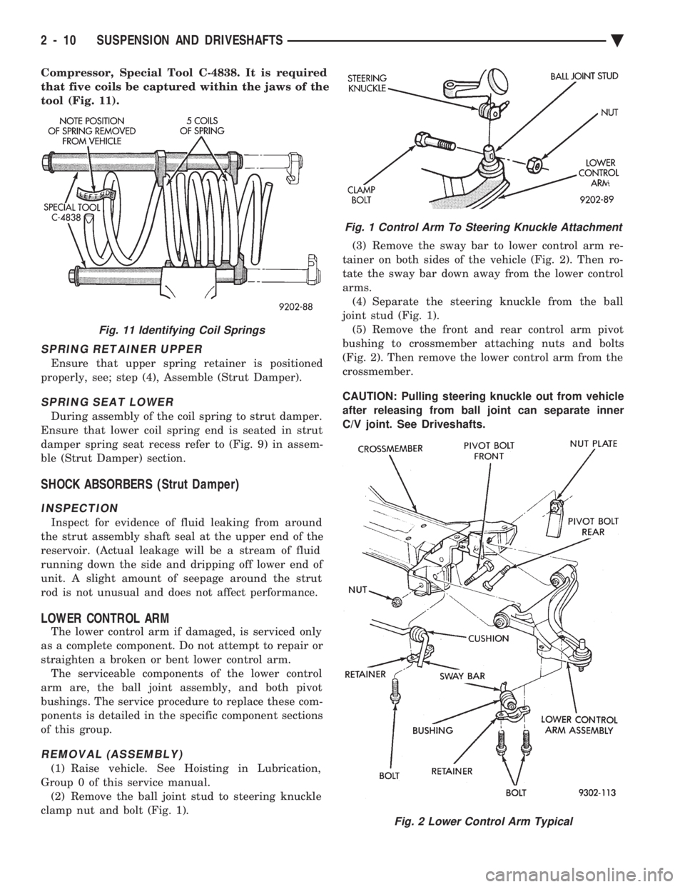
Compressor, Special Tool C-4838. It is required
that five coils be captured within the jaws of the
tool (Fig. 11).
SPRING RETAINER UPPER
Ensure that upper spring retainer is positioned
properly, see; step (4), Assemble (Strut Damper).
SPRING SEAT LOWER
During assembly of the coil spring to strut damper.
Ensure that lower coil spring end is seated in strut
damper spring seat recess refer to (Fig. 9) in assem-
ble (Strut Damper) section.
SHOCK ABSORBERS (Strut Damper)
INSPECTION
Inspect for evidence of fluid leaking from around
the strut assembly shaft seal at the upper end of the
reservoir. (Actual leakage will be a stream of fluid
running down the side and dripping off lower end of
unit. A slight amount of seepage around the strut
rod is not unusual and does not affect performance.
LOWER CONTROL ARM
The lower control arm if damaged, is serviced only
as a complete component. Do not attempt to repair or
straighten a broken or bent lower control arm. The serviceable components of the lower control
arm are, the ball joint assembly, and both pivot
bushings. The service procedure to replace these com-
ponents is detailed in the specific component sections
of this group.
REMOVAL (ASSEMBLY)
(1) Raise vehicle. See Hoisting in Lubrication,
Group 0 of this service manual. (2) Remove the ball joint stud to steering knuckle
clamp nut and bolt (Fig. 1). (3) Remove the sway bar to lower control arm re-
tainer on both sides of the vehicle (Fig. 2). Then ro-
tate the sway bar down away from the lower control
arms. (4) Separate the steering knuckle from the ball
joint stud (Fig. 1). (5) Remove the front and rear control arm pivot
bushing to crossmember attaching nuts and bolts
(Fig. 2). Then remove the lower control arm from the
crossmember.
CAUTION: Pulling steering knuckle out from vehicle
after releasing from ball joint can separate inner
C/V joint. See Driveshafts.
Fig. 11 Identifying Coil Springs
Fig. 1 Control Arm To Steering Knuckle Attachment
Fig. 2 Lower Control Arm Typical
2 - 10 SUSPENSION AND DRIVESHAFTS Ä
Page 97 of 2438
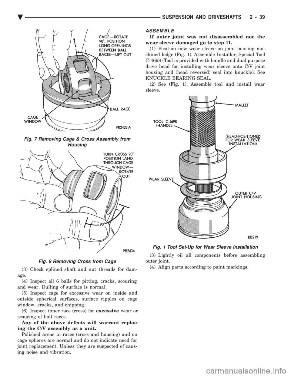
(3) Check splined shaft and nut threads for dam-
age. (4) Inspect all 6 balls for pitting, cracks, scouring
and wear. Dulling of surface is normal. (5) Inspect cage for excessive wear on inside and
outside spherical surfaces, surface ripples on cage
window, cracks, and chipping. (6) Inspect inner race (cross) for excessivewear or
scouring of ball races. Any of the above defects will warrant replac-
ing the C/V assembly as a unit. Polished areas in races (cross and housing) and on
cage spheres are normal and do not indicate need for
joint replacement. Unless they are suspected of caus-
ing noise and vibration.
ASSEMBLE
If outer joint was not disassembled nor the
wear sleeve damaged go to step 11. (1) Position new wear sleeve on joint housing ma-
chined ledge (Fig. 1). Assemble Installer, Special Tool
C-4698 (Tool is provided with handle and dual purpose
drive head for installing wear sleeve onto C/V joint
housing and (head reversed) seal into knuckle). See
KNUCKLE BEARING SEAL. (2) See (Fig. 1). Assemble tool and install wear
sleeve.
(3) Lightly oil all components before assembling
outer joint. (4) Align parts according to paint markings.
Fig. 7 Removing Cage & Cross Assembly from Housing
Fig. 8 Removing Cross from Cage
Fig. 1 Tool Set-Up for Wear Sleeve Installation
Ä SUSPENSION AND DRIVESHAFTS 2 - 39
Page 99 of 2438
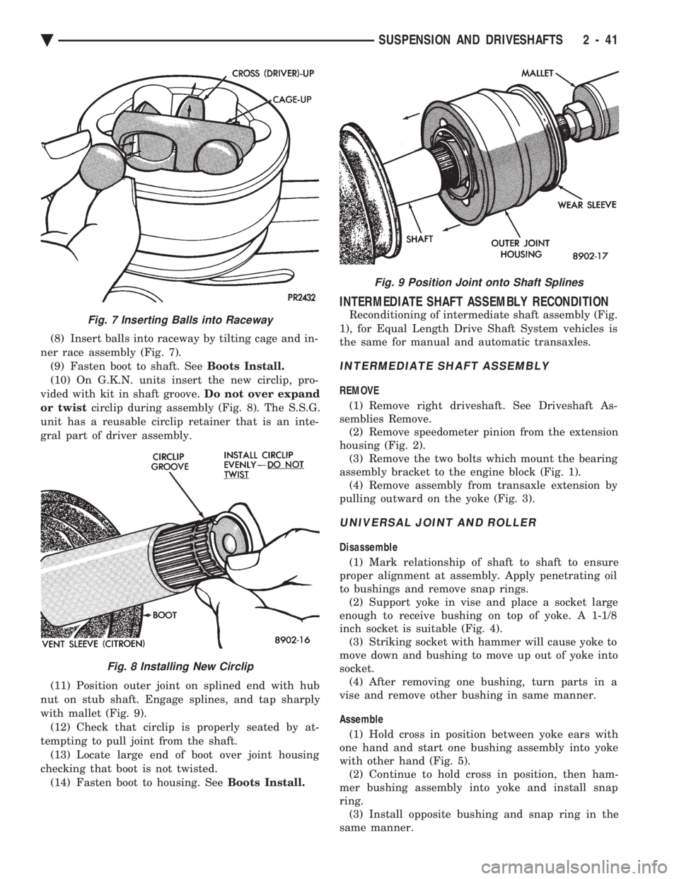
(8) Insert balls into raceway by tilting cage and in-
ner race assembly (Fig. 7). (9) Fasten boot to shaft. See Boots Install.
(10) On G.K.N. units insert the new circlip, pro-
vided with kit in shaft groove. Do not over expand
or twist circlip during assembly (Fig. 8). The S.S.G.
unit has a reusable circlip retainer that is an inte-
gral part of driver assembly.
(11) Position outer joint on splined end with hub
nut on stub shaft. Engage splines, and tap sharply
with mallet (Fig. 9). (12) Check that circlip is properly seated by at-
tempting to pull joint from the shaft. (13) Locate large end of boot over joint housing
checking that boot is not twisted. (14) Fasten boot to housing. See Boots Install.
INTERMEDIATE SHAFT ASSEMBLY RECONDITION
Reconditioning of intermediate shaft assembly (Fig.
1), for Equal Length Drive Shaft System vehicles is
the same for manual and automatic transaxles.
INTERMEDIATE SHAFT ASSEMBLY
REMOVE
(1) Remove right driveshaft. See Driveshaft As-
semblies Remove. (2) Remove speedometer pinion from the extension
housing (Fig. 2). (3) Remove the two bolts which mount the bearing
assembly bracket to the engine block (Fig. 1). (4) Remove assembly from transaxle extension by
pulling outward on the yoke (Fig. 3).
UNIVERSAL JOINT AND ROLLER
Disassemble
(1) Mark relationship of shaft to shaft to ensure
proper alignment at assembly. Apply penetrating oil
to bushings and remove snap rings. (2) Support yoke in vise and place a socket large
enough to receive bushing on top of yoke. A 1-1/8
inch socket is suitable (Fig. 4). (3) Striking socket with hammer will cause yoke to
move down and bushing to move up out of yoke into
socket. (4) After removing one bushing, turn parts in a
vise and remove other bushing in same manner.
Assemble (1) Hold cross in position between yoke ears with
one hand and start one bushing assembly into yoke
with other hand (Fig. 5). (2) Continue to hold cross in position, then ham-
mer bushing assembly into yoke and install snap
ring. (3) Install opposite bushing and snap ring in the
same manner.
Fig. 7 Inserting Balls into Raceway
Fig. 8 Installing New Circlip
Fig. 9 Position Joint onto Shaft Splines
Ä SUSPENSION AND DRIVESHAFTS 2 - 41
Page 102 of 2438
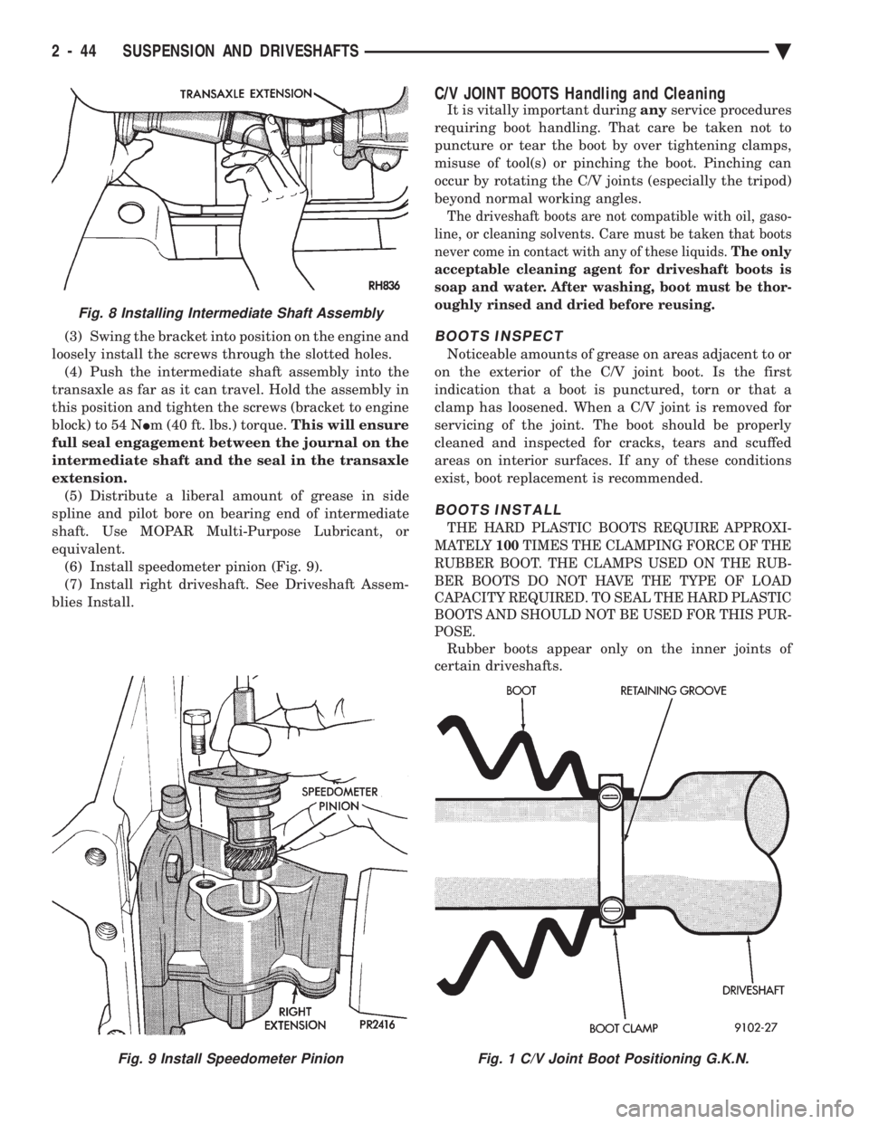
(3) Swing the bracket into position on the engine and
loosely install the screws through the slotted holes. (4) Push the intermediate shaft assembly into the
transaxle as far as it can travel. Hold the assembly in
this position and tighten the screws (bracket to engine
block) to 54 N Im (40 ft. lbs.) torque. This will ensure
full seal engagement between the journal on the
intermediate shaft and the seal in the transaxle
extension. (5) Distribute a liberal amount of grease in side
spline and pilot bore on bearing end of intermediate
shaft. Use MOPAR Multi-Purpose Lubricant, or
equivalent. (6) Install speedometer pinion (Fig. 9).
(7) Install right driveshaft. See Driveshaft Assem-
blies Install.
C/V JOINT BOOTS Handling and Cleaning
It is vitally important during anyservice procedures
requiring boot handling. That care be taken not to
puncture or tear the boot by over tightening clamps,
misuse of tool(s) or pinching the boot. Pinching can
occur by rotating the C/V joints (especially the tripod)
beyond normal working angles.
The driveshaft boots are not compatible with oil, gaso-
line, or cleaning solvents. Care must be taken that boots
never come in contact with any of these liquids. The only
acceptable cleaning agent for driveshaft boots is
soap and water. After washing, boot must be thor-
oughly rinsed and dried before reusing.
BOOTS INSPECT
Noticeable amounts of grease on areas adjacent to or
on the exterior of the C/V joint boot. Is the first
indication that a boot is punctured, torn or that a
clamp has loosened. When a C/V joint is removed for
servicing of the joint. The boot should be properly
cleaned and inspected for cracks, tears and scuffed
areas on interior surfaces. If any of these conditions
exist, boot replacement is recommended.
BOOTS INSTALL
THE HARD PLASTIC BOOTS REQUIRE APPROXI-
MATELY 100TIMES THE CLAMPING FORCE OF THE
RUBBER BOOT. THE CLAMPS USED ON THE RUB-
BER BOOTS DO NOT HAVE THE TYPE OF LOAD
CAPACITY REQUIRED. TO SEAL THE HARD PLASTIC
BOOTS AND SHOULD NOT BE USED FOR THIS PUR-
POSE.
Rubber boots appear only on the inner joints of
certain driveshafts.
Fig. 9 Install Speedometer PinionFig. 1 C/V Joint Boot Positioning G.K.N.
Fig. 8 Installing Intermediate Shaft Assembly
2 - 44 SUSPENSION AND DRIVESHAFTS Ä
Page 108 of 2438
REAR SUSPENSION INDEX
page page
Coil Springs and Jounce Bumper ............ 51
General Information ....................... 50
Pivot Bushing AC AG AJ AP Body ........... 55
Pivot Bushing AC and AY Body ............. 52 Rear Axle Assembly
...................... 57
Shock Absorbers ......................... 51
Track Bar-Brace-Bracket ................... 52
GENERAL INFORMATION
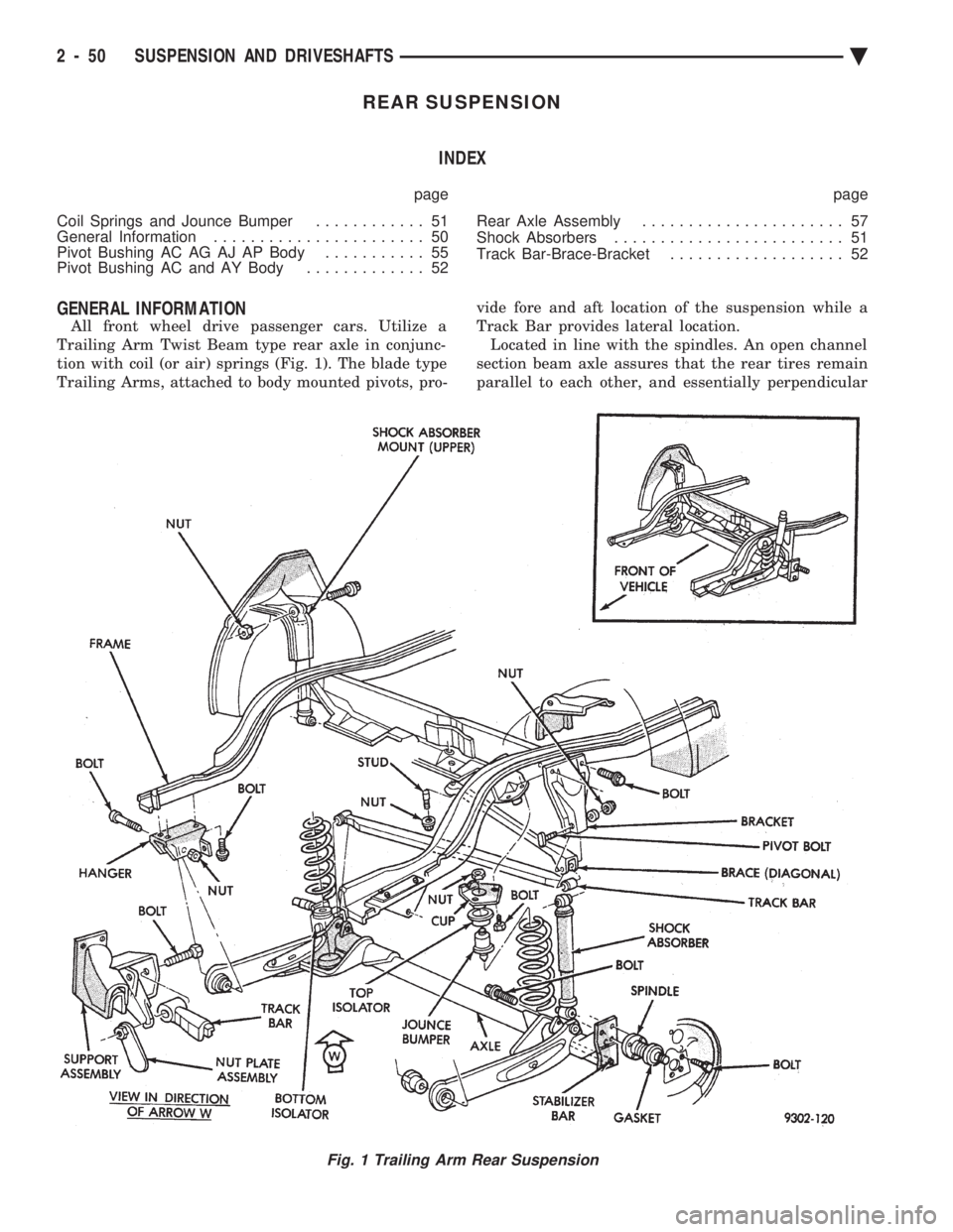
All front wheel drive passenger cars. Utilize a
Trailing Arm Twist Beam type rear axle in conjunc-
tion with coil (or air) springs (Fig. 1). The blade type
Trailing Arms, attached to body mounted pivots, pro- vide fore and aft location of the suspension while a
Track Bar provides lateral location. Located in line with the spindles. An open channel
section beam axle assures that the rear tires remain
parallel to each other, and essentially perpendicular
Fig. 1 Trailing Arm Rear Suspension
2 - 50 SUSPENSION AND DRIVESHAFTS Ä