1993 CHEVROLET DYNASTY oil
[x] Cancel search: oilPage 50 of 2438

PCV SYSTEM TEST
Refer to group 25, Emission Control System for
proper procedures to test PCV system.
FUEL RECOMMENDATIONS
Chrysler Corporation recommends that only fuel pur-
chased from a reputable retailer be used. Use high qual-
ity, unleaded gasoline to provide satisfactory
driveability and highest fuel economy. Gasoline contain-
ing detergent and corrosion control additives are desire-
able. If the engine develops spark knock (audible ping),
poor performance, hard starting or stalling, purchase
fuel from another source. Engine performance can vary
when using different brands of gasoline with the same
octane rating. Occasional light engine spark knock un-
der heavy acceleration, at low speed or when vehicle is
heavily loaded is not harmful. Extended periods of
spark knock under moderate acceleration or at cruising
speed can damage the engine. The cause of excessive
spark knock condition must be diagnosed and corrected.
For diagnostic procedures refer to Group 14, Fuel Sys-
tem and Powertrain Diagnostic Procedures manual.
SELECTING GASOLINE
CAUTION:Do not use fuel containing METHANOL
(methyl or wood alcohol), damage to fuel system
will result. Do not use leaded gasoline, damage to catalytic
converter will result and vehicle will not conform to
emission control standards.
ETHANOL, MTBE OR ETBE BLENDS
All Chrysler Corporation vehicles are designed to
use unleaded gasoline ONLY. Gasohol blends, con-
taining 10% Ethanol (ethyl or grain alcohol) 90% un-
leaded gasoline can be used provided it has adequate
octane rating. Fuel blends containing up to 15% MTBE (Methyl
Tertiary Butyl Ether) and 85% unleaded gasoline can
be used. Fuel blends containing up to 17% ETBE
(Ethyl Tertiary Butyl Ether) and 83% unleaded gas-
oline can also be used. Fuel blended with ethanol, MTBE or ETBE are
also referred to as reformulated or clean air gasoline.
These fuels contribute less emissions to the atmo-
sphere. Chrysler Corporation recommends that
blended fuels be used when available
METHANOL BLENDS Using gasoline blended with methanol can result
in starting and driveability problems. Deterioration
of fuel system components will result. Methanol in-
duced problems are not the responsibility of Chrysler
Corporation and may not be covered by the vehicle
warranty. NON-TURBOCHARGED ENGINES
Use regular unleaded gasoline having a minimum
octane rating of 87 (R+M)/2. Higher octane premium
unleaded gasoline can be used if desired.
2.2L 16 VALVE TURBOCHARGED ENGINE
Use premium unleaded gasoline having a mini-
mum octane rating of 91 (R+M)/2. Gasoline with oc-
tane rating less than 91 (R+M)/2 can be used if
recommended gasoline is not available. Low octane
gasoline will reduce engine performance.
FLEXIBLE FUEL VEHICLES
CAUTION: Do not use 100% methanol, damage to
fuel system can result. Use unleaded regular gasoline having a minimum
octane rating of 87 (R=M)/2 and M85 fuel that is
85% methanol and 15% unleaded gasoline, or a mix-
ture of these two.
FUEL FILTER
The fuel filter requires service only when a fuel
contamination problem is suspected. For proper diag-
nostic and service procedures refer to Group 14, Fuel
System,
IGNITION CABLES, DISTRIBUTOR CAP, AND
ROTOR
Inspect and test ignition cables, distributor cap and
rotor when the spark plugs are replaced. Oil and
grime should be cleaned from the ignition cables and
distributor cap to avoid possible spark plug fouling.
Mopar, Foamy Engine Degreaser, or equivalent is
recommended for cleaning the engine compartment.
For proper service and diagnostic procedures refer to
Group 8D, Ignition System.
SPARK PLUGS
Ignition spark plugs should be replaced at the
mileage interval described in the Lubrication and
Maintenance Schedules. Refer to the General Infor-
mation section of this group. For proper service pro-
cedures refer to Group 8D, Ignition Systems.
DRIVE BELTS
Inspect and adjust drive belts at the interval de-
scribed in the Lubrication and Maintenance Sched-
ules. Refer to General Information section of this
group. For proper inspection and adjustment proce-
dures, see Group 7, Cooling System.
EMISSION CONTROL SYSTEM
Inspect all emission control components and hoses
when other under hood service is performed. Refer to
emission system Vacuum Hose Label located on the
0 - 14 LUBRICATION AND MAINTENANCE Ä
Page 51 of 2438
inside of the hood in the engine compartment and
Group 25, Emission Control Systems for proper ser-
vice procedures.
BATTERY
Inspect battery tray, hold down and terminal con-
nections when other under hood service is performed.
For proper diagnostic procedures refer to Group 8A,
Battery/Starting/Charging System Diagnostics. For
service and cleaning procedures refer to Group 8B,
Battery/Starter Service.
RUBBER AND PLASTIC COMPONENT INSPECTION
CAUTION: Plastic hoses or wire harness covers will
melt or deform when exposed to heat from exhaust
system or engine manifolds. Position plastic or rubber components away from
moving parts in engine compartment or under vehi-
cle, or damage will result. Do not allow rubber engine mounts or other com-
ponents to become oil contaminated, repair cause
of oil contamination and clean area. All rubber and plastic components should be in-
spected when engine compartment or under vehicle
service is performed. When evidence of deterioration
exists, replacement is required. To reduce deteriora-
tion of rubber components, Chrysler Corporation rec-
ommends Mopar Foamy Engine Degreaser or
equivalent be used to clean engine compartment of
oil and road grime.
EXHAUST SYSTEM ISOLATOR AND HANGER
The exhaust system should be inspected when un-
der vehicle service is performed. The exhaust system
should not make contact with under body, brake ca-
bles, brake/fuel lines, fuel tank or suspension compo-
nents. Slight cracking in rubber isolator or hanger is
acceptable. Severely cracked or broken rubber compo-
nents must be replaced. For proper service proce-
dures see Group 11, Exhaust System and Intake
Manifold.
Ä LUBRICATION AND MAINTENANCE 0 - 15
Page 52 of 2438
DRIVETRAIN INDEX
page page
Automatic Transaxle ...................... 16
Automatic Transaxle Floor Shift .............. 16
Clutch and Gearshift Linkage ............... 16
Drive Shaft Cv and Tripod Joint Boots ........ 17 Front Wheel Bearings
..................... 17
Manual Transaxle ........................ 16
Tires .................................. 17
CLUTCH AND GEARSHIFT LINKAGE
If the clutch or gearshift begins to operate with dif-
ficulty, squeak or grunt, the cables and linkage
should be lubricated before service replacement is
performed. For proper lubrication and service proce-
dures refer to Group 6, Clutch, or Group 21, Manual
Transaxle.
MANUAL TRANSAXLE
The manual transaxle should be inspected for oil
leaks and proper oil level when other under vehicle
service is performed. To inspect the transaxle oil
level, position the vehicle on a level surface. Remove
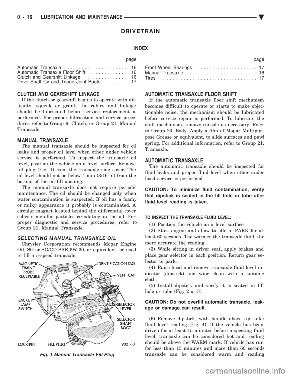
fill plug (Fig. 1) from the transaxle side cover. The
oil level should not be below 4 mm (3/16 in) from the
bottom of the oil fill opening. The manual transaxle does not require periodic
maintenance. The oil should be changed only when
water contamination is suspected. If oil has a foamy
or milky appearance it probably is contaminated. A
circular magnet located behind the differential cover
collects metallic particles circulating in the oil. For
proper diagnostic and service procedures, refer to
Group 21, Manual Transaxle.
SELECTING MANUAL TRANSAXLE OIL
Chrysler Corporation recommends Mopar Engine
Oil, SG or SG/CD SAE 5W-30, or equivalent, be used
to fill a 5-speed transaxle.
AUTOMATIC TRANSAXLE FLOOR SHIFT
If the automatic transaxle floor shift mechanism
becomes difficult to operate or starts to make objec-
tionable noise, the mechanism should be lubricated
before service repair is performed. To lubricate the
shift mechanism, remove console as necessary. Refer
to Group 23, Body. Apply a film of Mopar Multipur-
pose Grease or equivalent, to slide surfaces and pawl
spring. For additional information, refer to Group 21,
Transaxle.
AUTOMATIC TRANSAXLE
The automatic transaxle should be inspected for
fluid leaks and proper fluid level when other under
hood service is performed.
CAUTION: To minimize fluid contamination, verify
that dipstick is seated in the fill hole or tube after
fluid level reading is taken.
TO INSPECT THE TRANSAXLE FLUID LEVEL: (1) Position the vehicle on a level surface.
(2) Start engine and allow to idle in PARK for at
least 60 seconds. The warmer the transaxle fluid, the
more accurate the reading. (3) While sitting in driver seat, apply brakes and
place gear selector in each position. Return gear se-
lector to park. (4) Raise hood and remove transaxle fluid level in-
dicator (dipstick) and wipe clean with a suitable
cloth. (5) Install dipstick and verify it is seated in fill
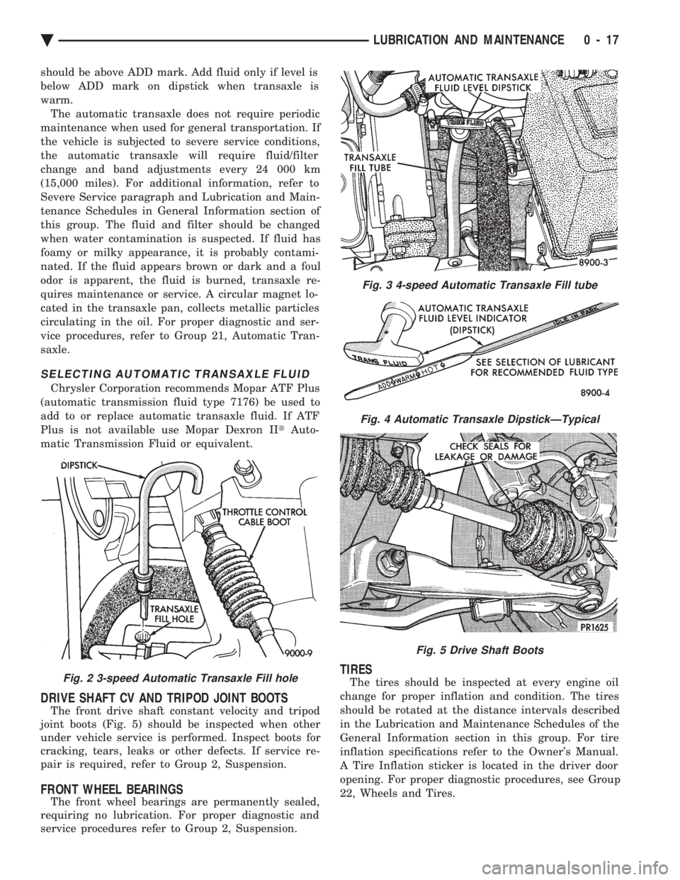
hole or tube (Fig. 2 or 3).
CAUTION: Do not overfill automatic transaxle, leak-
age or damage can result.
(6) Remove dipstick, with handle above tip, take
fluid level reading (Fig. 4). If the vehicle has been
driven for at least 15 minutes before inspecting fluid
level, transaxle can be considered hot and reading
should be above the WARM mark. If vehicle has run
for less than 15 minutes and more than 60 seconds
transaxle can be considered warm and reading
Fig. 1 Manual Transaxle Fill Plug
0 - 16 LUBRICATION AND MAINTENANCE Ä
Page 53 of 2438
should be above ADD mark. Add fluid only if level is
below ADD mark on dipstick when transaxle is
warm.The automatic transaxle does not require periodic
maintenance when used for general transportation. If
the vehicle is subjected to severe service conditions,
the automatic transaxle will require fluid/filter
change and band adjustments every 24 000 km
(15,000 miles). For additional information, refer to
Severe Service paragraph and Lubrication and Main-
tenance Schedules in General Information section of
this group. The fluid and filter should be changed
when water contamination is suspected. If fluid has
foamy or milky appearance, it is probably contami-
nated. If the fluid appears brown or dark and a foul
odor is apparent, the fluid is burned, transaxle re-
quires maintenance or service. A circular magnet lo-
cated in the transaxle pan, collects metallic particles
circulating in the oil. For proper diagnostic and ser-
vice procedures, refer to Group 21, Automatic Tran-
saxle.
SELECTING AUTOMATIC TRANSAXLE FLUID
Chrysler Corporation recommends Mopar ATF Plus
(automatic transmission fluid type 7176) be used to
add to or replace automatic transaxle fluid. If ATF
Plus is not available use Mopar Dexron II tAuto-
matic Transmission Fluid or equivalent.
DRIVE SHAFT CV AND TRIPOD JOINT BOOTS
The front drive shaft constant velocity and tripod
joint boots (Fig. 5) should be inspected when other
under vehicle service is performed. Inspect boots for
cracking, tears, leaks or other defects. If service re-
pair is required, refer to Group 2, Suspension.
FRONT WHEEL BEARINGS
The front wheel bearings are permanently sealed,
requiring no lubrication. For proper diagnostic and
service procedures refer to Group 2, Suspension.
TIRES
The tires should be inspected at every engine oil
change for proper inflation and condition. The tires
should be rotated at the distance intervals described
in the Lubrication and Maintenance Schedules of the
General Information section in this group. For tire
inflation specifications refer to the Owner's Manual.
A Tire Inflation sticker is located in the driver door
opening. For proper diagnostic procedures, see Group
22, Wheels and Tires.Fig. 2 3-speed Automatic Transaxle Fill hole
Fig. 3 4-speed Automatic Transaxle Fill tube
Fig. 4 Automatic Transaxle DipstickÐTypical
Fig. 5 Drive Shaft Boots
Ä LUBRICATION AND MAINTENANCE 0 - 17
Page 55 of 2438
CHASSIS AND BODY INDEX
page page
Body Lubrication ......................... 22
Brakes ................................ 21
Headlamps ............................. 22
Lower Ball Joints ......................... 19 Power Steering
.......................... 19
Rear Wheel Bearings ..................... 20
Steering Linkage ......................... 19
STEERING LINKAGE
INSPECTION
The steering linkage and steering gear should be in-
spected for wear, leaks or damage when other under ve-
hicle service is performed. The rack and pinion steering
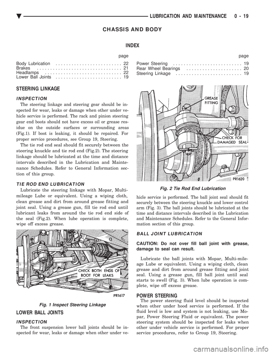
gear end boots should not have excess oil or grease res-
idue on the outside surfaces or surrounding areas
(Fig.1). If boot is leaking, it should be repaired. For
proper service procedures, see Group 19, Steering.
The tie rod end seal should fit securely between the
steering knuckle and tie rod end (Fig.2). The steering
linkage should be lubricated at the time and distance
intervals described in the Lubrication and Mainte-
nance Schedules. Refer to General Information sec-
tion of this group.
TIE ROD END LUBRICATION
Lubricate the steering linkage with Mopar, Multi-
mileage Lube or equivalent. Using a wiping cloth,
clean grease and dirt from around grease fitting and
joint seal. Using a grease gun, fill tie rod end until
lubricant leaks from around the tie rod end side of
the seal (Fig.2). When lube operation is complete,
wipe off excess grease.
LOWER BALL JOINTS
INSPECTION
The front suspension lower ball joints should be in-
spected for wear, leaks or damage when other under ve- hicle service is performed. The ball joint seal should fit
securely between the steering knuckle and lower control
arm (Fig. 3). The ball joints should be lubricated at the
time and distance intervals described in the Lubrication
and Maintenance Schedules. Refer to the General Infor-
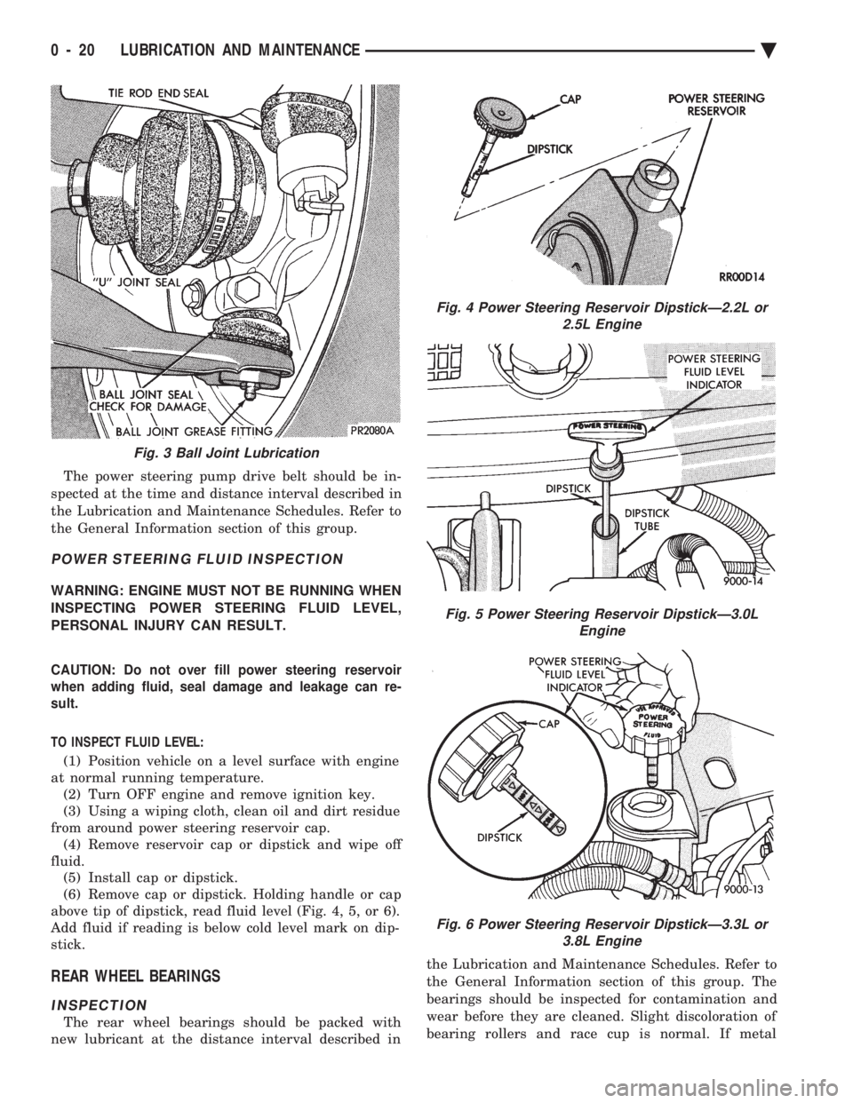
mation section of this group.
BALL JOINT LUBRICATION
CAUTION: Do not over fill ball joint with grease,
damage to seal can result.
Lubricate the ball joints with Mopar, Multi-mile-
age Lube or equivalent. Using a wiping cloth, clean
grease and dirt from around grease fitting and joint
seal. Using a grease gun, fill ball joint until seal
starts to swell (Fig. 3). When lube operation is com-
plete, wipe off excess grease.
POWER STEERING
The power steering fluid level should be inspected
when other under hood service is performed. If the
fluid level is low and system is not leaking, use Mo-
par, Power Steering Fluid or equivalent. The power
steering system should be inspected for leaks when
other under vehicle service is performed. For proper
service procedures, refer to Group 19, Steering.Fig. 1 Inspect Steering Linkage
Fig. 2 Tie Rod End Lubrication
Ä LUBRICATION AND MAINTENANCE 0 - 19
Page 56 of 2438
The power steering pump drive belt should be in-
spected at the time and distance interval described in
the Lubrication and Maintenance Schedules. Refer to
the General Information section of this group.
POWER STEERING FLUID INSPECTION
WARNING: ENGINE MUST NOT BE RUNNING WHEN
INSPECTING POWER STEERING FLUID LEVEL,
PERSONAL INJURY CAN RESULT.
CAUTION: Do not over fill power steering reservoir
when adding fluid, seal damage and leakage can re-
sult.
TO INSPECT FLUID LEVEL:
(1) Position vehicle on a level surface with engine
at normal running temperature. (2) Turn OFF engine and remove ignition key.
(3) Using a wiping cloth, clean oil and dirt residue
from around power steering reservoir cap. (4) Remove reservoir cap or dipstick and wipe off
fluid. (5) Install cap or dipstick.
(6) Remove cap or dipstick. Holding handle or cap
above tip of dipstick, read fluid level (Fig. 4, 5, or 6).
Add fluid if reading is below cold level mark on dip-
stick.
REAR WHEEL BEARINGS
INSPECTION
The rear wheel bearings should be packed with
new lubricant at the distance interval described in the Lubrication and Maintenance Schedules. Refer to
the General Information section of this group. The
bearings should be inspected for contamination and
wear before they are cleaned. Slight discoloration of
bearing rollers and race cup is normal. If metal
Fig. 3 Ball Joint Lubrication
Fig. 4 Power Steering Reservoir DipstickÐ2.2L or 2.5L Engine
Fig. 5 Power Steering Reservoir DipstickÐ3.0L Engine
Fig. 6 Power Steering Reservoir DipstickÐ3.3L or3.8L Engine
0 - 20 LUBRICATION AND MAINTENANCE Ä
Page 58 of 2438
BRAKE RESERVOIR LEVEL INSPECTION
WARNING: DO NOT ALLOW PETROLEUM OR WATER
BASE LIQUIDS TO CONTAMINATE BRAKE FLUID,
SEAL DAMAGE AND BRAKE FAILURE CAN RESULT.
RELIEVE PRESSURE IN ANTI-LOCK BRAKE SYS-
TEM BEFORE ADDING BRAKE FLUID TO RESER-
VOIR. IF NOT, BRAKE FLUID COULD DISCHARGED
FROM THE RESERVOIR POSSIBLY CAUSING PER-
SONAL INJURY.
The brake reservoir level should be inspected when
other under hood service is performed. It is normal
for the reservoir level to drop as disc brake pads
wear. When fluid must be added, use Mopar, Brake
Fluid or equivalent. Use only brake fluid conforming
to DOT 3, Federal, Department of Transportation
specification. To avoid brake fluid contamination, use
fluid from a properly sealed container. On vehicles with anti-lock brakes, depressurize the
system before inspecting fluid level. Turn OFF the
ignition and remove the key. Pump the brake pedal
at least 50 times to relieve the pressure in the sys-
tem.
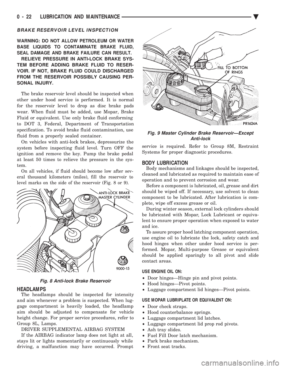
On all vehicles, if fluid should become low after sev-
eral thousand kilometers (miles), fill the reservoir to
level marks on the side of the reservoir (Fig. 8 or 9).
HEADLAMPS
The headlamps should be inspected for intensity
and aim whenever a problem is suspected. When lug-
gage compartment is heavily loaded, the headlamp
aim should be adjusted to compensate for vehicle
height change. For proper service procedures, refer to
Group 8L, Lamps. DRIVER SUPPLEMENTAL AIRBAG SYSTEM
If the AIRBAG indicator lamp does not light at all,
stays lit or lights momentarily or continuously while
driving, a malfunction may have occurred. Prompt service is required. Refer to Group 8M, Restraint
Systems for proper diagnostic procedures.
BODY LUBRICATION
Body mechanisms and linkages should be inspected,
cleaned and lubricated as required to maintain ease of
operation and to prevent corrosion and wear. Before a component is lubricated, oil, grease and dirt
should be wiped off. If necessary, use solvent to clean
component to be lubricated. After lubrication is com-
plete, wipe off excess grease or oil. During winter season, external lock cylinders should
be lubricated with Mopar, Lock Lubricant or equiva-
lent to ensure proper operation when exposed to water
and ice. To assure proper hood latching component operation,
use engine oil to lubricate the lock, safety catch and
hood hinges when other under hood service is per-
formed. Mopar, Multi-purpose Grease or equivalent
should be applied sparingly to all pivot and slide
contact areas.
USE ENGINE OIL ON:
² Door hingesÐHinge pin and pivot points.
² Hood hingesÐPivot points.
² Luggage compartment lid hingesÐPivot points.
USE MOPAR LUBRIPLATE OR EQUIVALENT ON:
² Door check straps.
² Hood counterbalance springs.
² Luggage compartment lid latches.
² Luggage compartment lid prop rod pivots.
² Ash tray slides.
² Fuel Fill Door latch mechanism.
² Park brake mechanism.
² Front seat tracks.
Fig. 8 Anti-lock Brake Reservoir
Fig. 9 Master Cylinder Brake ReservoirÐExcept
Anti-lock
0 - 22 LUBRICATION AND MAINTENANCE Ä
Page 60 of 2438
FRONT SUSPENSION
FRONT SUSPENSION MAJOR COMPONENTS (FIG. 2)
STRUT SUPPORT
The system is supported by coil springs positioned
offset around the struts. The springs are contained
between an upper seat, located just below the top
strut mount assembly (Fig. 2) and a lower spring
seat on the strut lower housing. The top of each strut assembly is bolted to the up-
per fender reinforcement (shock tower) through a
rubber isolated mount. The bottom attaches to the top of the steering
knuckle with two through bolts. On some vehicles,
one bolt has an eccentric cam located below the head
of the bolt for camber adjustment. On the other ve-
hicles the camber adjustment is done by manually
moving the steering knuckle within the strut assem-
bly. Caster is a fixed setting on all vehicles and is
not adjustable.
STEERING KNUCKLE
The steering knuckle is a single casting with legs
machined for attachment to the strut damper, steer-
ing linkage, brake adaptor, and lower control arm
ball joint. The knuckle also holds the front drive hub
bearing. The hub is positioned through the bearing
and knuckle, with the constant velocity stub shaft
splined through the hub.
LOWER CONTROL ARM
The lower control arm is a steel casting with 2
large spool type rubber pivot bushings. The lower
control arm is bolted to the crossmember with pivot
bolts through the center of the rubber pivot bush-
ings. The ball joint is pressed into the control arm and
has a non-tapered stud with a notch for clamp bolt
clearance. The stud is clamped and locked into the
steering knuckle leg with a clamp bolt. The lower control arms are inter-connected through
a rubber isolated sway bar (Fig. 2).
DRIVESHAFTS
A left and right driveshaft is attached inboard to
the transaxle differential side gears, and outboard to
the driven wheel hub. To deliver driving force from the transaxle to the
front wheels during turning maneuvers and suspen-
sion movement. Both shafts are constructed with con-
stant velocity universal joints at both ends. Both shafts have a Tripod (sliding) joint at the
transaxle end and Rzeppa joints (with splined stub
shafts) on the hub ends. Due to the transaxle loca-
tion the connecting shafts between the C/V joints are
of different length and construction. The right shaft
is longer and of tubular construction. The left shaft
is solid.
2 - 2 SUSPENSION AND DRIVESHAFTS Ä