1993 CHEVROLET DYNASTY oil
[x] Cancel search: oilPage 365 of 2438
FAN SHROUD
All vehicles have fan shrouds to improve fan air
flow efficiency. These fan shrouds cover less than full
radiator frontal area to prevent the shroud from re-
stricting air flow at high speeds. The shroud supports the electric fan motor and fan.
For removal and installation see Radiator Section.
AUTOMATIC TRANSMISSION OIL COOLERS
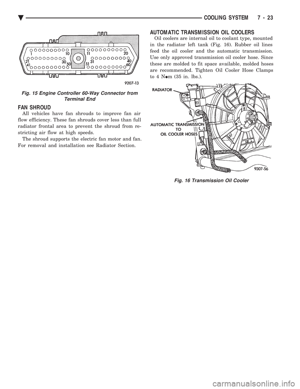
Oil coolers are internal oil to coolant type, mounted
in the radiator left tank (Fig. 16). Rubber oil lines
feed the oil cooler and the automatic transmission.
Use only approved transmission oil cooler hose. Since
these are molded to fit space available, molded hoses
are recommended. Tighten Oil Cooler Hose Clamps
to4N Im (35 in. lbs.).
Fig. 15 Engine Controller 60-Way Connector from
Terminal End
Fig. 16 Transmission Oil Cooler
Ä COOLING SYSTEM 7 - 23
Page 379 of 2438

After 15 seconds, record the loaded voltage reading
and return the load control to the off position. (6) Voltage drop will vary according to battery
temperature at the time of the load test. Battery
temperature can be estimated by the temperature of
exposure over the preceding several hours. If the bat-
tery has been charged, boosted, or loaded a few min-
utes prior to the test, the battery would be slightly
warmer. Refer to Fig. 14 for proper loaded voltage
reading.
(7) If battery passes load test, it is in good condi-
tion and further tests are not necessary. If it fails
load test, it should be replaced.
BATTERY CHARGING
A battery is considered fully charged when it will
meet all the following requirements:
² It has an open circuit voltage charge of at least
12.4 volts (Fig. 9)
² It passes the 15 second load test (Fig. 14)
² The built in test indicator dot is GREEN (Fig. 5)
² The battery cannot be refilled with water. It must
be replaced WARNING: DO NOT CHARGE A BATTERY THAT
HAS EXCESSIVELY LOW ELECTROLYTE LEVEL.
BATTERY MAY SPARK INTERNALLY AND EX-
PLODE. EXPLOSIVE GASES FORM OVER THE BATTERY.
DO NOT SMOKE, USE FLAME, OR CREATE
SPARKS NEAR BATTERY. DO NOT ASSIST BOOST OR CHARGE A FROZEN
BATTERY. BATTERY CASING MAY FRACTURE. BATTERY ACID IS POISON, AND MAY CAUSE SE-
VERE BURNS AND THE BATTERY CONTAIN SUL-
FURIC ACID. AVOID CONTACT WITH SKIN, EYES,
OR CLOTHING. IN THE EVENT OF CONTACT,
FLUSH WITH WATER AND CALL PHYSICIAN IMME-
DIATELY. KEEP OUT OF REACH OF CHILDREN.
CAUTION: Disconnect the battery negative cable
first (Fig. 15) before charging battery to avoid dam-
age to electrical systems. Do not exceed 16.0 volts
while charging battery. Refer to the instructions
supplied with charging equipment
Battery electrolyte will bubble inside the battery
case while being charged properly. If the electrolyte
boils violently, or is discharged from the vent holes
while charging, immediately reduce charging rate or
turn off charger. Evaluate battery condition. Battery
damage may occur if charging is excessive. Some battery chargers are equipped with polarity
sensing devices to protect the charger or battery from
being damaged if improperly connected. If the bat-
tery state of charge is too low for the polarity sensor
to detect, the sensor must be bypassed for charger to
operate. Refer to operating instructions provided
with battery charger being used.
CAUTION: Charge battery until test indicator ap-
pears green. Do not overcharge.
It may be necessary to jiggle the battery or vehicle
to bring the green dot (in the test indicator) into
view. After the battery has been charged to 12.4 volts or
greater, perform a load test to decide cranking capac-
Fig. 13 Load 50 Percent Cold Crank Rating
Fig. 14 Load Test Temperature
Fig. 15 Disconnect Negative Battery Cable
Ä BATTERY/STARTING/CHARGING SYSTEMS DIAGNOSTICS 8A - 7
Page 383 of 2438
STARTER TEST PROCEDURES ON VEHICLE INDEX
page page
Diagnostic Preparation ..................... 11
General Information ....................... 11 Starter Control Circuit Tests
................ 15
Starter Feed Circuit Tests .................. 11
GENERAL INFORMATION
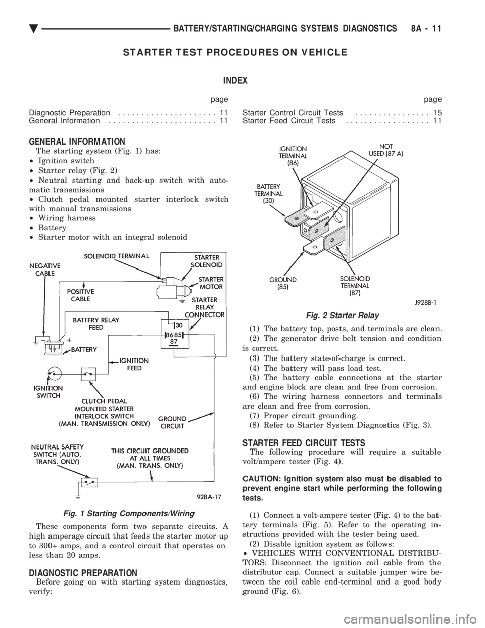
The starting system (Fig. 1) has:
² Ignition switch
² Starter relay (Fig. 2)
² Neutral starting and back-up switch with auto-
matic transmissions
² Clutch pedal mounted starter interlock switch
with manual transmissions
² Wiring harness
² Battery
² Starter motor with an integral solenoid
These components form two separate circuits. A
high amperage circuit that feeds the starter motor up
to 300+ amps, and a control circuit that operates on
less than 20 amps.
DIAGNOSTIC PREPARATION
Before going on with starting system diagnostics,
verify: (1) The battery top, posts, and terminals are clean.
(2) The generator drive belt tension and condition
is correct. (3) The battery state-of-charge is correct.
(4) The battery will pass load test.
(5) The battery cable connections at the starter
and engine block are clean and free from corrosion. (6) The wiring harness connectors and terminals
are clean and free from corrosion. (7) Proper circuit grounding.
(8) Refer to Starter System Diagnostics (Fig. 3).
STARTER FEED CIRCUIT TESTS
The following procedure will require a suitable
volt/ampere tester (Fig. 4).
CAUTION: Ignition system also must be disabled to
prevent engine start while performing the following
tests.
(1) Connect a volt-ampere tester (Fig. 4) to the bat-
tery terminals (Fig. 5). Refer to the operating in-
structions provided with the tester being used. (2) Disable ignition system as follows:
² VEHICLES WITH CONVENTIONAL DISTRIBU-
TORS: Disconnect the ignition coil cable from the
distributor cap. Connect a suitable jumper wire be-
tween the coil cable end-terminal and a good body
ground (Fig. 6).
Fig. 1 Starting Components/Wiring
Fig. 2 Starter Relay
Ä BATTERY/STARTING/CHARGING SYSTEMS DIAGNOSTICS 8A - 11
Page 385 of 2438
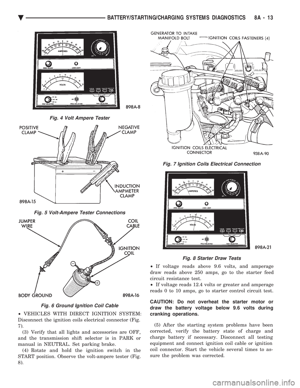
² VEHICLES WITH DIRECT IGNITION SYSTEM:
Disconnect the ignition coils electrical connector (Fig.
7). (3) Verify that all lights and accessories are OFF,
and the transmission shift selector is in PARK or
manual in NEUTRAL. Set parking brake. (4) Rotate and hold the ignition switch in the
START position. Observe the volt-ampere tester (Fig.
8). ²
If voltage reads above 9.6 volts, and amperage
draw reads above 250 amps, go to the starter feed
circuit resistance test.
² If voltage reads 12.4 volts or greater and amperage
reads 0 to 10 amps, go to starter control circuit test.
CAUTION: Do not overheat the starter motor or
draw the battery voltage below 9.6 volts during
cranking operations.
(5) After the starting system problems have been
corrected, verify the battery state of charge and
charge battery if necessary. Disconnect all testing
equipment and connect ignition coil cable or ignition
coil connector. Start the vehicle several times to as-
sure the problem was corrected.
Fig. 4 Volt Ampere Tester
Fig. 5 Volt-Ampere Tester Connections
Fig. 6 Ground Ignition Coil Cable
Fig. 7 Ignition Coils Electrical Connection
Fig. 8 Starter Draw Tests
Ä BATTERY/STARTING/CHARGING SYSTEMS DIAGNOSTICS 8A - 13
Page 386 of 2438
STARTER FEED CIRCUIT RESISTANCE TEST
Before going on with this operation, review Diag-
nostic Preparation and Starter Feed Circuit Tests.
The following operation will require a voltmeter, ac-
curate to 1/10 of a volt.
CAUTION: Ignition system also must be disabled to
prevent engine start while performing the following
tests.
(1) Disable ignition system as follows:
² VEHICLES WITH CONVENTIONAL DISTRIBU-
TORS: Disconnect the ignition coil cable from the
distributor cap. Connect a suitable jumper wire be-
tween the coil cable end-terminal and a good body
ground (Fig. 6).
² VEHICLES WITH DIRECT IGNITION SYSTEM:
Disconnect the ignition coils electrical connector (Fig.
7). (2) With all wiring harnesses and components
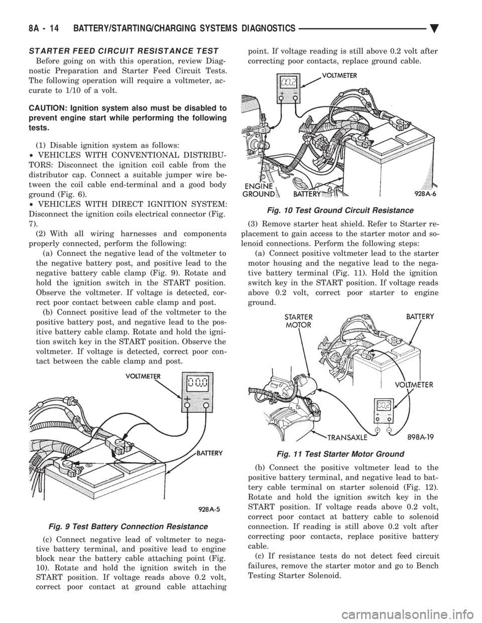
properly connected, perform the following: (a) Connect the negative lead of the voltmeter to
the negative battery post, and positive lead to the
negative battery cable clamp (Fig. 9). Rotate and
hold the ignition switch in the START position.
Observe the voltmeter. If voltage is detected, cor-
rect poor contact between cable clamp and post. (b) Connect positive lead of the voltmeter to the
positive battery post, and negative lead to the pos-
itive battery cable clamp. Rotate and hold the igni-
tion switch key in the START position. Observe the
voltmeter. If voltage is detected, correct poor con-
tact between the cable clamp and post.
(c) Connect negative lead of voltmeter to nega-
tive battery terminal, and positive lead to engine
block near the battery cable attaching point (Fig.
10). Rotate and hold the ignition switch in the
START position. If voltage reads above 0.2 volt,
correct poor contact at ground cable attaching point. If voltage reading is still above 0.2 volt after
correcting poor contacts, replace ground cable.
(3) Remove starter heat shield. Refer to Starter re-
placement to gain access to the starter motor and so-
lenoid connections. Perform the following steps: (a) Connect positive voltmeter lead to the starter
motor housing and the negative lead to the nega-
tive battery terminal (Fig. 11). Hold the ignition
switch key in the START position. If voltage reads
above 0.2 volt, correct poor starter to engine
ground.
(b) Connect the positive voltmeter lead to the
positive battery terminal, and negative lead to bat-
tery cable terminal on starter solenoid (Fig. 12).
Rotate and hold the ignition switch key in the
START position. If voltage reads above 0.2 volt,
correct poor contact at battery cable to solenoid
connection. If reading is still above 0.2 volt after
correcting poor contacts, replace positive battery
cable. (c) If resistance tests do not detect feed circuit
failures, remove the starter motor and go to Bench
Testing Starter Solenoid.
Fig. 9 Test Battery Connection Resistance
Fig. 10 Test Ground Circuit Resistance
Fig. 11 Test Starter Motor Ground
8A - 14 BATTERY/STARTING/CHARGING SYSTEMS DIAGNOSTICS Ä
Page 387 of 2438

STARTER CONTROL CIRCUIT TESTS
The starter control circuit has:
² Starter solenoid
² Starter relay (Fig. 2)
² Neutral starting and back-up switch with auto-
matic transmissions
² Clutch pedal mounted starter interlock switch
with manual transmissions
² Ignition switch
² Battery
² All related wiring and connections
CAUTION: Before performing any starter tests, the
ignition system must be disabled.
² VEHICLES EQUIPPED WITH A CONVEN-
TIONAL DISTRIBUTOR: Disconnect coil wire from
distributor cap center tower. Secure wire to a good
ground to prevent engine from starting (Fig. 6).
² VEHICLES EQUIPPED WITH DIRECT IGNI-
TION SYSTEM: Unplug the coils electrical connector
(Fig. 7).
STARTER SOLENOID TEST
WARNING: CHECK TO ENSURE THAT THE TRANS-
MISSION IS IN PARK OR NEUTRAL WITH THE
PARKING BRAKE APPLIED
(1) Verify battery condition. Battery must be in
good condition with a full charge before performing
any starter tests. Refer to Battery Tests. (2) Perform this starter solenoid test BEFORE per-
forming the starter relay test. (3) Raise the vehicle.
(4) Perform a visual inspection of the starter/
starter solenoid for corrosion, loose connections or
faulty wiring. (5) Lower the vehicle.
(6) Locate the starter relay as follows:
² On AC, AG, AJ and AY Bodies the relay is located
in the Power Distribution Center. This Center is mounted near the front of the left front strut tower
(Fig. 13). The position of the starter relay within this
Center will be shown on the Center cover.
² On AA/AP Bodies the relay is located on the front
of the left front strut tower (Fig. 14).
(7) Remove the starter relay from the connector.
(8) Connect a remote starter switch or a jumper
wire between the battery positive post and terminal
87 on the starter relay connector. To decide the
starter relay terminal numbers, refer to the Starter
Relay Tests.
² If engine now cranks, starter/starter solenoid is
good. Go to the starter relay test.
² If engine does not crank with this test, or solenoid
chatters, check wiring and connectors from starter
Fig. 12 Test Positive Battery Cable Resistance
Fig. 13 Starter Relay LocationÐAC, AG, AJ, and AY Bodies
Fig. 14 Starter Relay LocationÐAA/AP Body
Ä BATTERY/STARTING/CHARGING SYSTEMS DIAGNOSTICS 8A - 15
Page 388 of 2438
relay to starter solenoid for loose or corroded connec-
tions. Particularly at starter terminals.
² Repeat test. If engine still fails to crank properly,
trouble is within starter or starter mounted solenoid,
and it must be removed for repairs. Refer to Group
8B, Battery/Starter/Generator Service, Starter re-
placement.
STARTER RELAY TEST
WARNING: CHECK TO ENSURE THAT THE TRANS-
MISSION IS IN PARK OR NEUTRAL WITH THE
PARKING BRAKE APPLIED
(1) Verify battery condition. Battery must be in
good condition with a full charge before performing
any starter tests. Refer to Battery Tests. (2) Perform the preceding starter solenoid tests
BEFORE performing starter relay tests. Refer to
Starter Solenoid Test. (3) Locate and remove the starter relay. For
starter relay locations, refer to Starter Solenoid Test
(Fig. 13 or 14). (4) After the starter relay has been located and re-
moved, refer to Starter Relay Tests (Fig. 15).
NEUTRAL STARTING AND BACK-UP SWITCH
AUTOMATIC TRANSMISSION ONLY
For electrical diagnostics, when checking starter
circuits, refer to Starter Relay Tests (Fig. 15). For replacement of switch, refer to Group 21, Tran-
saxle, Neutral Starting and Switch Replacement.
STARTER INTERLOCK SWITCHÐCLUTCH PEDAL MOUNTED
MANUAL TRANSMISSION ONLY
For electrical diagnostics, refer to the Starter Relay
Tests. For replacement and/or adjustment of the switch,
refer to Group 6, Manual Transaxle Clutch, Manual
Transaxle Starter Interlock Switch.
IGNITION SWITCH TEST
After testing the starter solenoid and relay, test ig-
nition switch and wiring. Refer to Group 8D, Ignition
Systems, or the Front Wheel Drive Car Wiring Dia-
grams Service Manual. Check all wiring for opens or
shorts, and all connectors for being loose or corroded.
BENCH TESTING STARTER SOLENOID
(1) Disconnect field coil wire from field coil termi-
nal (Fig. 16 or 17). (2) Check for continuity between solenoid terminal
and field coil terminal with a continuity tester. Con-
tinuity should be detected (Fig. 18 or 19). (3) Check for continuity between solenoid terminal
and solenoid housing (Fig. 20 or 21). Continuity
should be detected. If continuity is detected, solenoid
is good. (4) If continuity is not detected in either test, sole-
noid has an open circuit and is defective. If equipped
with:
² BOSCH STARTER: Replace the solenoid.
² NIPPONDENSO STARTER: Replace the starter
assembly.
8A - 16 BATTERY/STARTING/CHARGING SYSTEMS DIAGNOSTICS Ä
Page 390 of 2438
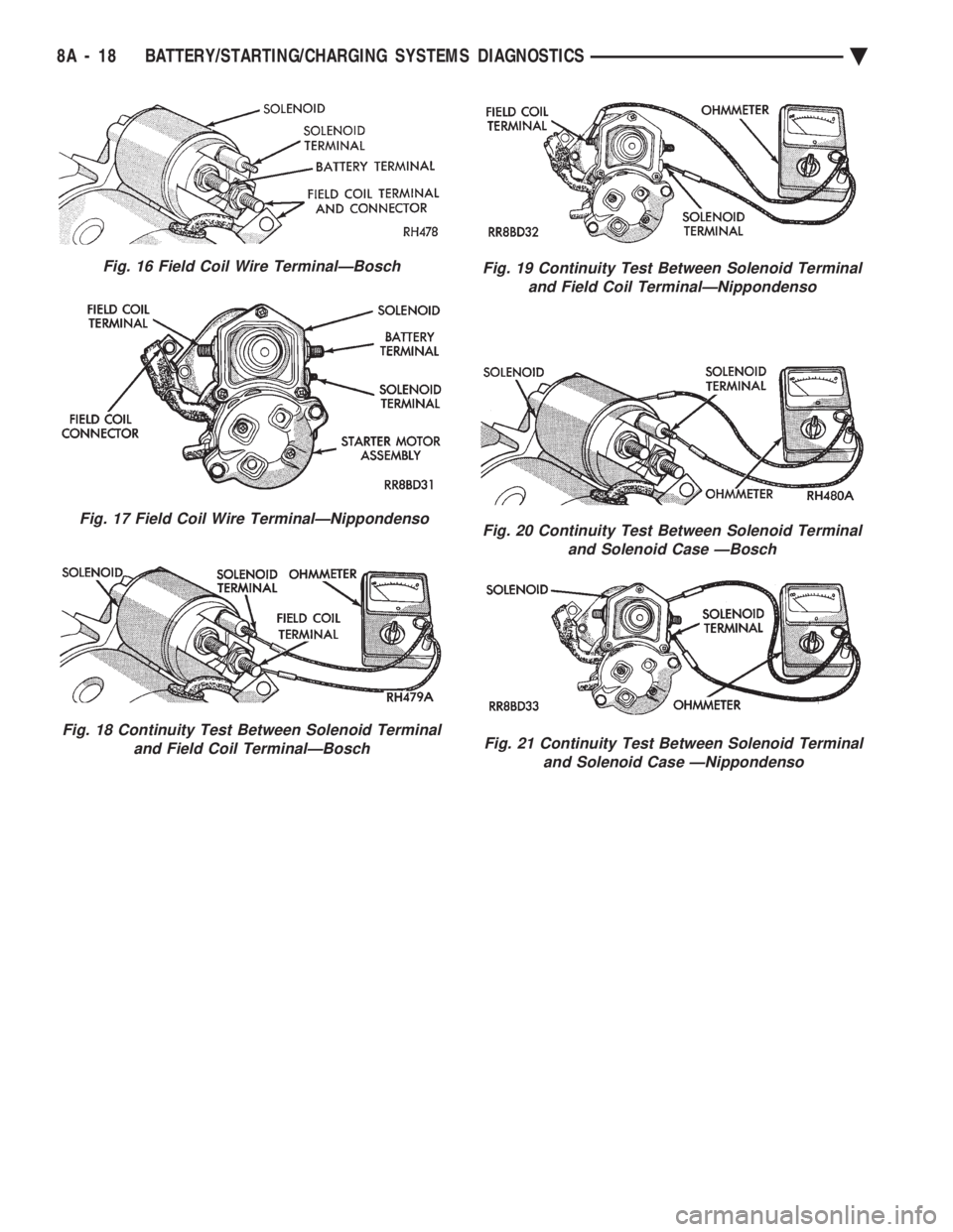
Fig. 16 Field Coil Wire TerminalÐBosch
Fig. 17 Field Coil Wire TerminalÐNippondenso
Fig. 18 Continuity Test Between Solenoid Terminal and Field Coil TerminalÐBosch
Fig. 19 Continuity Test Between Solenoid Terminaland Field Coil TerminalÐNippondenso
Fig. 20 Continuity Test Between Solenoid Terminal and Solenoid Case ÐBosch
Fig. 21 Continuity Test Between Solenoid Terminaland Solenoid Case ÐNippondenso
8A - 18 BATTERY/STARTING/CHARGING SYSTEMS DIAGNOSTICS Ä