1993 CHEVROLET DYNASTY wheel
[x] Cancel search: wheelPage 86 of 2438
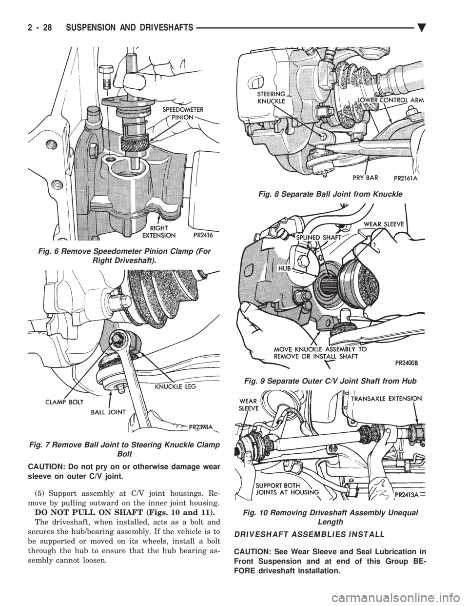
CAUTION: Do not pry on or otherwise damage wear
sleeve on outer C/V joint. (5) Support assembly at C/V joint housings. Re-
move by pulling outward on the inner joint housing. DO NOT PULL ON SHAFT (Figs. 10 and 11).
The driveshaft, when installed, acts as a bolt and
secures the hub/bearing assembly. If the vehicle is to
be supported or moved on its wheels, install a bolt
through the hub to ensure that the hub bearing as-
sembly cannot loosen.
DRIVESHAFT ASSEMBLIES INSTALL
CAUTION: See Wear Sleeve and Seal Lubrication in
Front Suspension and at end of this Group BE-
FORE driveshaft installation.
Fig. 6 Remove Speedometer Pinion Clamp (For Right Driveshaft).
Fig. 7 Remove Ball Joint to Steering Knuckle Clamp Bolt
Fig. 8 Separate Ball Joint from Knuckle
Fig. 9 Separate Outer C/V Joint Shaft from Hub
Fig. 10 Removing Driveshaft Assembly UnequalLength
2 - 28 SUSPENSION AND DRIVESHAFTS Ä
Page 88 of 2438
not to allow dirt to enter or grease to leave the boot
cavity. The clamp must be removed and discarded be-
fore the rod can be inserted. After venting, install a
new Service Clamp. (See Boots Install section at the
end of this group for details).
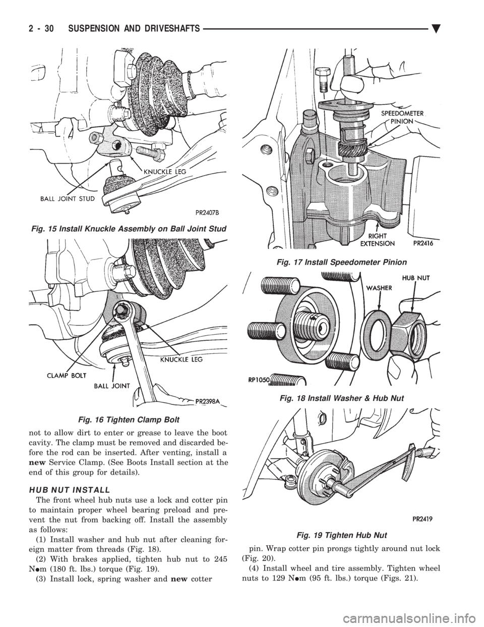
HUB NUT INSTALL
The front wheel hub nuts use a lock and cotter pin
to maintain proper wheel bearing preload and pre-
vent the nut from backing off. Install the assembly
as follows: (1) Install washer and hub nut after cleaning for-
eign matter from threads (Fig. 18). (2) With brakes applied, tighten hub nut to 245
N Im (180 ft. lbs.) torque (Fig. 19).
(3) Install lock, spring washer and newcotter pin. Wrap cotter pin prongs tightly around nut lock
(Fig. 20). (4) Install wheel and tire assembly. Tighten wheel
nuts to 129 N Im (95 ft. lbs.) torque (Figs. 21).
Fig. 15 Install Knuckle Assembly on Ball Joint Stud
Fig. 16 Tighten Clamp Bolt
Fig. 17 Install Speedometer Pinion
Fig. 18 Install Washer & Hub Nut
Fig. 19 Tighten Hub Nut
2 - 30 SUSPENSION AND DRIVESHAFTS Ä
Page 89 of 2438
DRIVESHAFT RECONDITIONING PROCEDURE
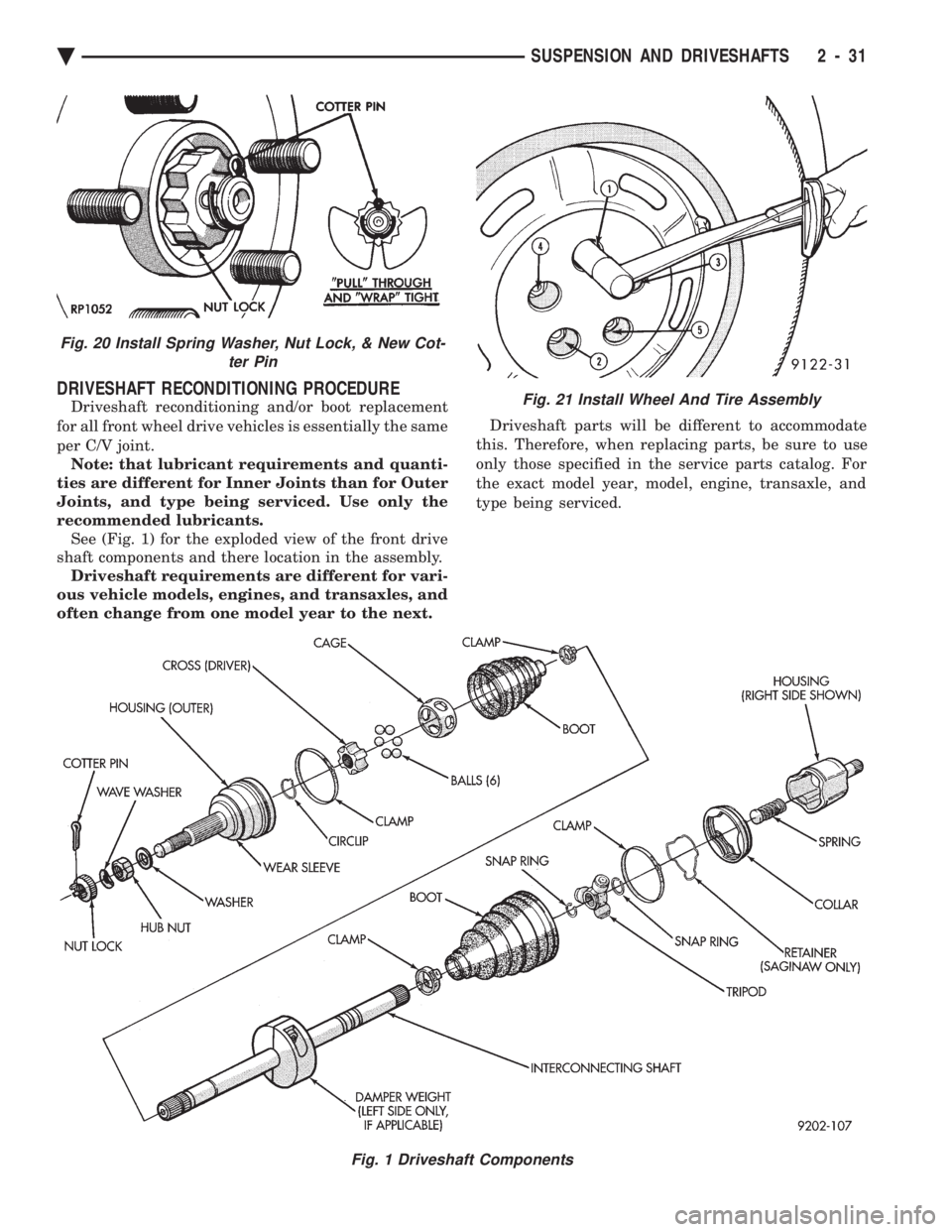
Driveshaft reconditioning and/or boot replacement
for all front wheel drive vehicles is essentially the same
per C/V joint. Note: that lubricant requirements and quanti-
ties are different for Inner Joints than for Outer
Joints, and type being serviced. Use only the
recommended lubricants. See (Fig. 1) for the exploded view of the front drive
shaft components and there location in the assembly. Driveshaft requirements are different for vari-
ous vehicle models, engines, and transaxles, and
often change from one model year to the next. Driveshaft parts will be different to accommodate
this. Therefore, when replacing parts, be sure to use
only those specified in the service parts catalog. For
the exact model year, model, engine, transaxle, and
type being serviced.
Fig. 1 Driveshaft Components
Fig. 21 Install Wheel And Tire Assembly
Fig. 20 Install Spring Washer, Nut Lock, & New Cot- ter Pin
Ä SUSPENSION AND DRIVESHAFTS 2 - 31
Page 106 of 2438
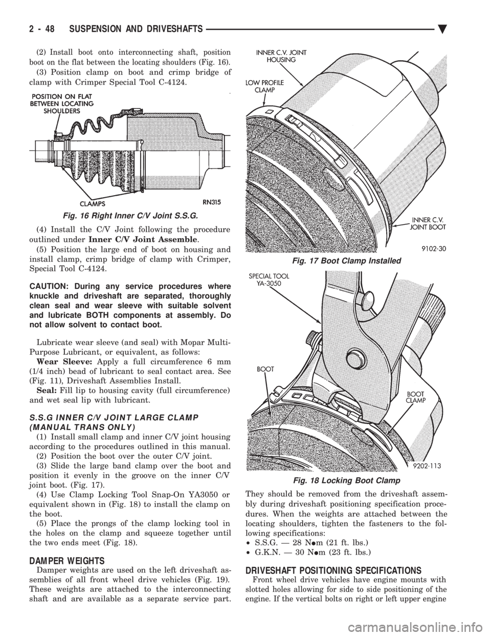
(2) Install boot onto interconnecting shaft, position
boot on the flat between the locating shoulders (Fig. 16).
(3) Position clamp on boot and crimp bridge of
clamp with Crimper Special Tool C-4124.
(4) Install the C/V Joint following the procedure
outlined under Inner C/V Joint Assemble .
(5) Position the large end of boot on housing and
install clamp, crimp bridge of clamp with Crimper,
Special Tool C-4124.
CAUTION: During any service procedures where
knuckle and driveshaft are separated, thoroughly
clean seal and wear sleeve with suitable solvent
and lubricate BOTH components at assembly. Do
not allow solvent to contact boot.
Lubricate wear sleeve (and seal) with Mopar Multi-
Purpose Lubricant, or equivalent, as follows: Wear Sleeve: Apply a full circumference 6 mm
(1/4 inch) bead of lubricant to seal contact area. See
(Fig. 11), Driveshaft Assemblies Install. Seal: Fill lip to housing cavity (full circumference)
and wet seal lip with lubricant.
S.S.G INNER C/V JOINT LARGE CLAMP (MANUAL TRANS ONLY)
(1) Install small clamp and inner C/V joint housing
according to the procedures outlined in this manual. (2) Position the boot over the outer C/V joint.
(3) Slide the large band clamp over the boot and
position it evenly in the groove on the inner C/V
joint boot. (Fig. 17). (4) Use Clamp Locking Tool Snap-On YA3050 or
equivalent shown in (Fig. 18) to install the clamp on
the boot. (5) Place the prongs of the clamp locking tool in
the holes on the clamp and squeeze together until
the two ends meet (Fig. 18).
DAMPER WEIGHTS
Damper weights are used on the left driveshaft as-
semblies of all front wheel drive vehicles (Fig. 19).
These weights are attached to the interconnecting
shaft and are available as a separate service part. They should be removed from the driveshaft assem-
bly during driveshaft positioning specification proce-
dures. When the weights are attached between the
locating shoulders, tighten the fasteners to the fol-
lowing specifications:
² S.S.G. Ð 28 N Im (21 ft. lbs.)
² G.K.N. Ð 30 N Im (23 ft. lbs.)DRIVESHAFT POSITIONING SPECIFICATIONS
Front wheel drive vehicles have engine mounts with
slotted holes allowing for side to side positioning of the
engine. If the vertical bolts on right or left upper engine
Fig. 16 Right Inner C/V Joint S.S.G.
Fig. 17 Boot Clamp Installed
Fig. 18 Locking Boot Clamp
2 - 48 SUSPENSION AND DRIVESHAFTS Ä
Page 107 of 2438
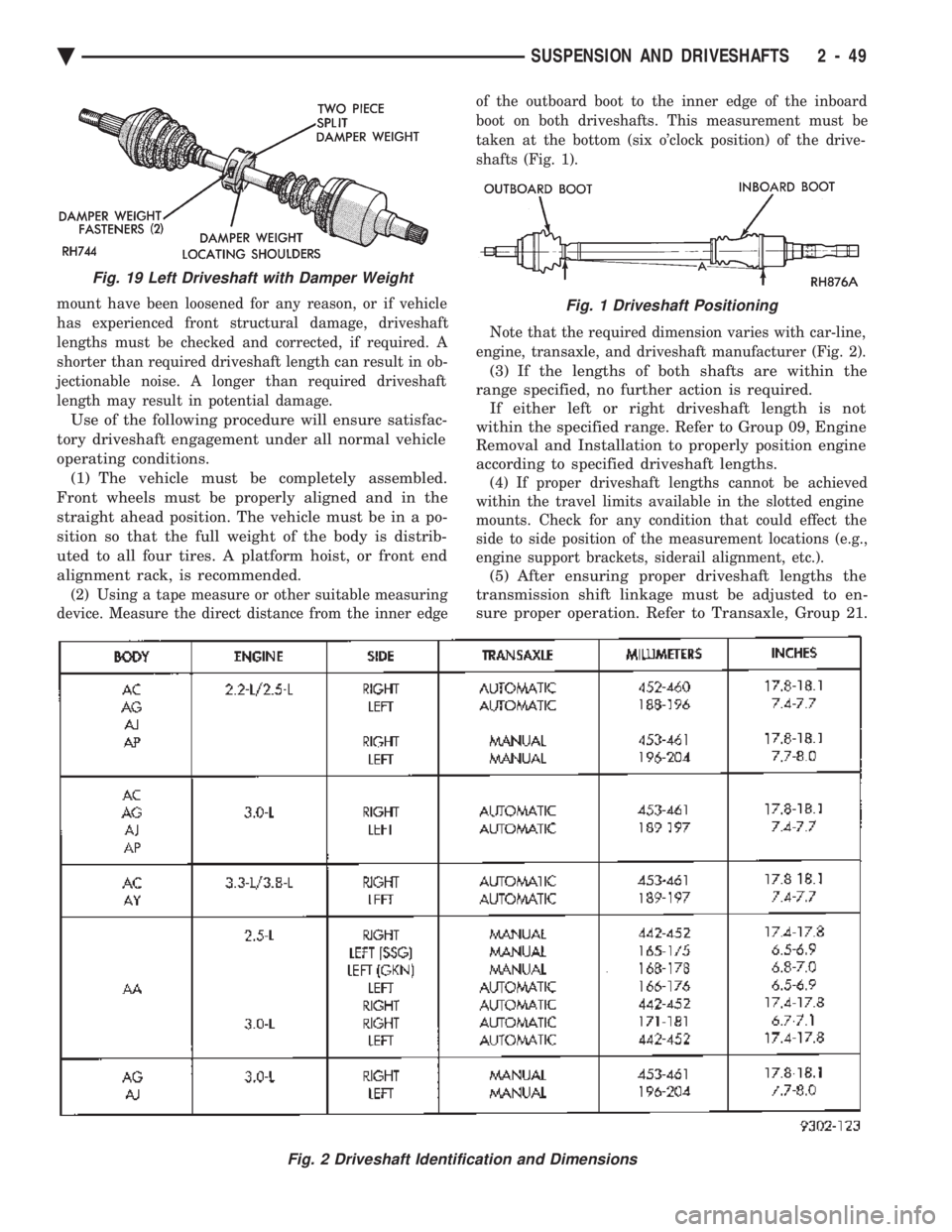
mount have been loosened for any reason, or if vehicle
has experienced front structural damage, driveshaft
lengths must be checked and corrected, if required. A
shorter than required driveshaft length can result in ob-
jectionable noise. A longer than required driveshaft
length may result in potential damage.
Use of the following procedure will ensure satisfac-
tory driveshaft engagement under all normal vehicle
operating conditions. (1) The vehicle must be completely assembled.
Front wheels must be properly aligned and in the
straight ahead position. The vehicle must be in a po-
sition so that the full weight of the body is distrib-
uted to all four tires. A platform hoist, or front end
alignment rack, is recommended.
(2) Using a tape measure or other suitable measuring
device. Measure the direct distance from the inner edge of the outboard boot to the inner edge of the inboard
boot on both driveshafts. This measurement must be
taken at the bottom (six o'clock position) of the drive-
shafts (Fig. 1).
Note that the required dimension varies with car-line,
engine, transaxle, and driveshaft manufacturer (Fig. 2).
(3) If the lengths of both shafts are within the
range specified, no further action is required. If either left or right driveshaft length is not
within the specified range. Refer to Group 09, Engine
Removal and Installation to properly position engine
according to specified driveshaft lengths.
(4) If proper driveshaft lengths cannot be achieved
within the travel limits available in the slotted engine
mounts. Check for any condition that could effect the
side to side position of the measurement locations (e.g.,
engine support brackets, siderail alignment, etc.).
(5) After ensuring proper driveshaft lengths the
transmission shift linkage must be adjusted to en-
sure proper operation. Refer to Transaxle, Group 21.
Fig. 2 Driveshaft Identification and Dimensions
Fig. 19 Left Driveshaft with Damper Weight
Fig. 1 Driveshaft Positioning
Ä SUSPENSION AND DRIVESHAFTS 2 - 49
Page 108 of 2438
REAR SUSPENSION INDEX
page page
Coil Springs and Jounce Bumper ............ 51
General Information ....................... 50
Pivot Bushing AC AG AJ AP Body ........... 55
Pivot Bushing AC and AY Body ............. 52 Rear Axle Assembly
...................... 57
Shock Absorbers ......................... 51
Track Bar-Brace-Bracket ................... 52
GENERAL INFORMATION
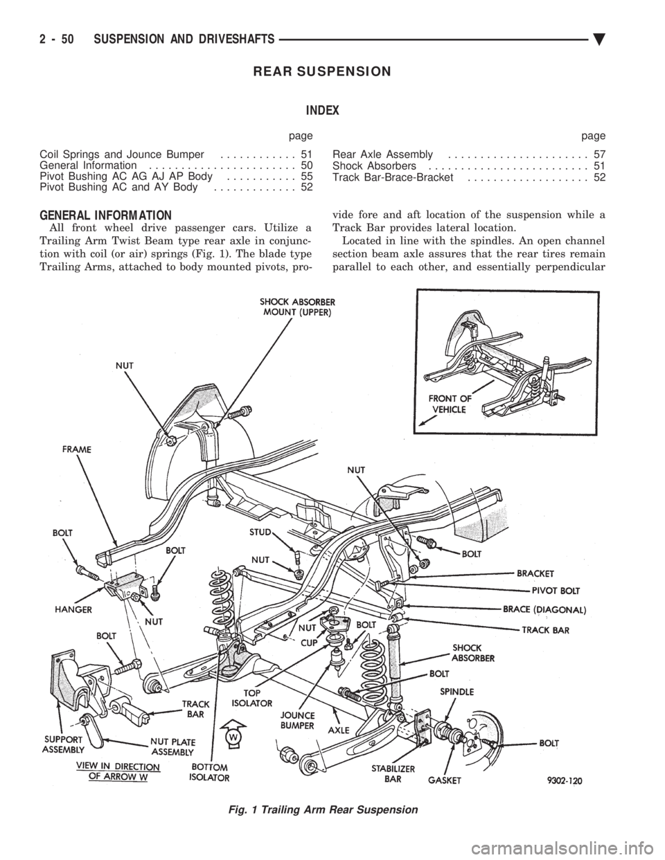
All front wheel drive passenger cars. Utilize a
Trailing Arm Twist Beam type rear axle in conjunc-
tion with coil (or air) springs (Fig. 1). The blade type
Trailing Arms, attached to body mounted pivots, pro- vide fore and aft location of the suspension while a
Track Bar provides lateral location. Located in line with the spindles. An open channel
section beam axle assures that the rear tires remain
parallel to each other, and essentially perpendicular
Fig. 1 Trailing Arm Rear Suspension
2 - 50 SUSPENSION AND DRIVESHAFTS Ä
Page 109 of 2438
to the road surface. While being able to twist as one
wheel moves vertically with respect to the other.Roll resistance is provided partly by the axle's re-
sistance to twist. But primarily by a torque tube or
rod (depending on the suspension option called for)
running through the channel and attached rigidly to
its end plates by welding. Because the torque tube/
rod is an integral part of the axle assembly, it cannot
be individually replaced. The spindles are bolted to the axle end (spindle
mounting) plates and can be individually replaced if
required. Rear wheel alignment changes require the
use of shims between the spindle and axle end plates.
SHOCK ABSORBERS
REMOVAL
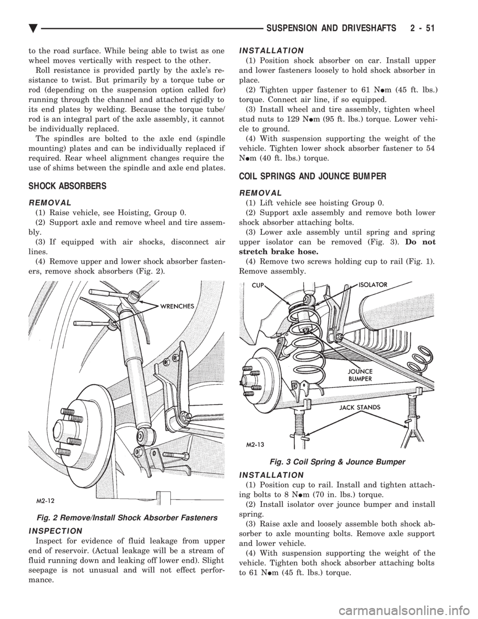
(1) Raise vehicle, see Hoisting, Group 0.
(2) Support axle and remove wheel and tire assem-
bly. (3) If equipped with air shocks, disconnect air
lines. (4) Remove upper and lower shock absorber fasten-
ers, remove shock absorbers (Fig. 2).
INSPECTION
Inspect for evidence of fluid leakage from upper
end of reservoir. (Actual leakage will be a stream of
fluid running down and leaking off lower end). Slight
seepage is not unusual and will not effect perfor-
mance.
INSTALLATION
(1) Position shock absorber on car. Install upper
and lower fasteners loosely to hold shock absorber in
place. (2) Tighten upper fastener to 61 N Im (45 ft. lbs.)
torque. Connect air line, if so equipped. (3) Install wheel and tire assembly, tighten wheel
stud nuts to 129 N Im (95 ft. lbs.) torque. Lower vehi-
cle to ground. (4) With suspension supporting the weight of the
vehicle. Tighten lower shock absorber fastener to 54
N Im (40 ft. lbs.) torque.
COIL SPRINGS AND JOUNCE BUMPER
REMOVAL
(1) Lift vehicle see hoisting Group 0.
(2) Support axle assembly and remove both lower
shock absorber attaching bolts. (3) Lower axle assembly until spring and spring
upper isolator can be removed (Fig. 3). Do not
stretch brake hose. (4) Remove two screws holding cup to rail (Fig. 1).
Remove assembly.
INSTALLATION
(1) Position cup to rail. Install and tighten attach-
ing bolts to 8 N Im (70 in. lbs.) torque.
(2) Install isolator over jounce bumper and install
spring. (3) Raise axle and loosely assemble both shock ab-
sorber to axle mounting bolts. Remove axle support
and lower vehicle. (4) With suspension supporting the weight of the
vehicle. Tighten both shock absorber attaching bolts
to 61 N Im (45 ft. lbs.) torque.
Fig. 2 Remove/Install Shock Absorber Fasteners
Fig. 3 Coil Spring & Jounce Bumper
Ä SUSPENSION AND DRIVESHAFTS 2 - 51
Page 115 of 2438
REAR AXLE ASSEMBLY
REMOVE
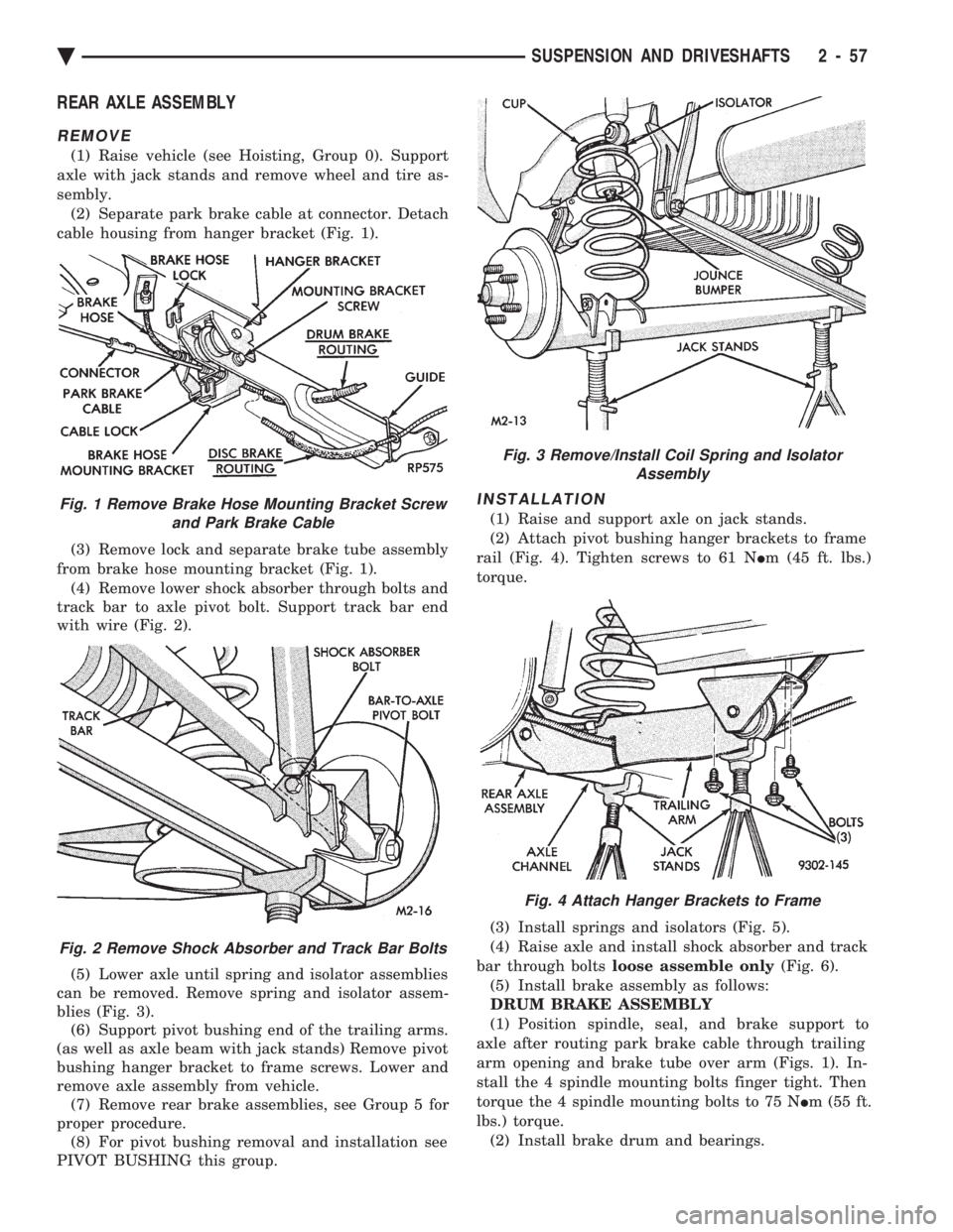
(1) Raise vehicle (see Hoisting, Group 0). Support
axle with jack stands and remove wheel and tire as-
sembly. (2) Separate park brake cable at connector. Detach
cable housing from hanger bracket (Fig. 1).
(3) Remove lock and separate brake tube assembly
from brake hose mounting bracket (Fig. 1). (4) Remove lower shock absorber through bolts and
track bar to axle pivot bolt. Support track bar end
with wire (Fig. 2).
(5) Lower axle until spring and isolator assemblies
can be removed. Remove spring and isolator assem-
blies (Fig. 3). (6) Support pivot bushing end of the trailing arms.
(as well as axle beam with jack stands) Remove pivot
bushing hanger bracket to frame screws. Lower and
remove axle assembly from vehicle. (7) Remove rear brake assemblies, see Group 5 for
proper procedure. (8) For pivot bushing removal and installation see
PIVOT BUSHING this group.
INSTALLATION
(1) Raise and support axle on jack stands.
(2) Attach pivot bushing hanger brackets to frame
rail (Fig. 4). Tighten screws to 61 N Im (45 ft. lbs.)
torque.
(3) Install springs and isolators (Fig. 5).
(4) Raise axle and install shock absorber and track
bar through bolts loose assemble only (Fig. 6).
(5) Install brake assembly as follows:
DRUM BRAKE ASSEMBLY
(1) Position spindle, seal, and brake support to
axle after routing park brake cable through trailing
arm opening and brake tube over arm (Figs. 1). In-
stall the 4 spindle mounting bolts finger tight. Then
torque the 4 spindle mounting bolts to 75 N Im (55 ft.
lbs.) torque. (2) Install brake drum and bearings.Fig. 1 Remove Brake Hose Mounting Bracket Screw and Park Brake Cable
Fig. 2 Remove Shock Absorber and Track Bar Bolts
Fig. 3 Remove/Install Coil Spring and Isolator Assembly
Fig. 4 Attach Hanger Brackets to Frame
Ä SUSPENSION AND DRIVESHAFTS 2 - 57