1993 CHEVROLET DYNASTY wheel
[x] Cancel search: wheelPage 71 of 2438
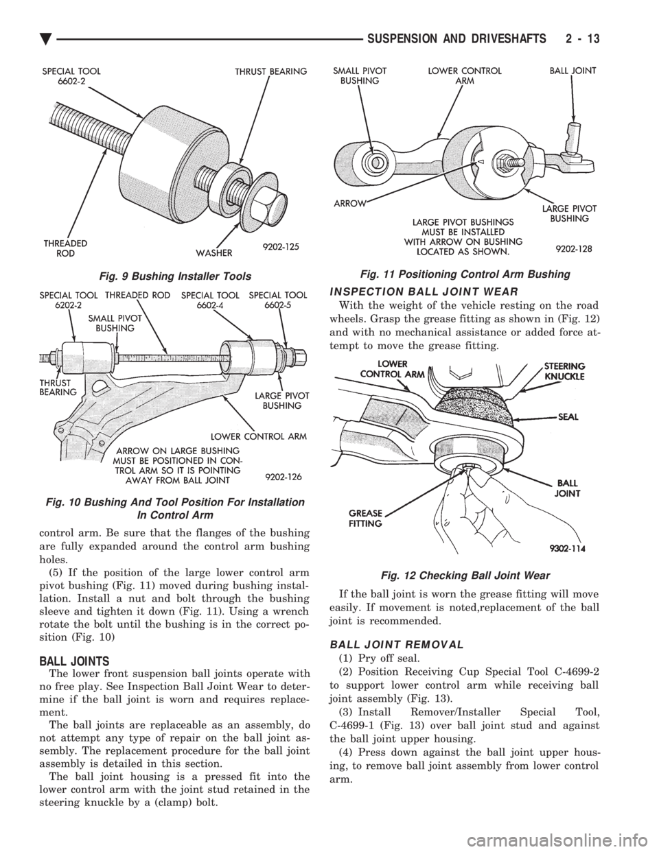
control arm. Be sure that the flanges of the bushing
are fully expanded around the control arm bushing
holes. (5) If the position of the large lower control arm
pivot bushing (Fig. 11) moved during bushing instal-
lation. Install a nut and bolt through the bushing
sleeve and tighten it down (Fig. 11). Using a wrench
rotate the bolt until the bushing is in the correct po-
sition (Fig. 10)
BALL JOINTS
The lower front suspension ball joints operate with
no free play. See Inspection Ball Joint Wear to deter-
mine if the ball joint is worn and requires replace-
ment. The ball joints are replaceable as an assembly, do
not attempt any type of repair on the ball joint as-
sembly. The replacement procedure for the ball joint
assembly is detailed in this section. The ball joint housing is a pressed fit into the
lower control arm with the joint stud retained in the
steering knuckle by a (clamp) bolt.
INSPECTION BALL JOINT WEAR
With the weight of the vehicle resting on the road
wheels. Grasp the grease fitting as shown in (Fig. 12)
and with no mechanical assistance or added force at-
tempt to move the grease fitting.
If the ball joint is worn the grease fitting will move
easily. If movement is noted,replacement of the ball
joint is recommended.
BALL JOINT REMOVAL
(1) Pry off seal.
(2) Position Receiving Cup Special Tool C-4699-2
to support lower control arm while receiving ball
joint assembly (Fig. 13). (3) Install Remover/Installer Special Tool,
C-4699-1 (Fig. 13) over ball joint stud and against
the ball joint upper housing. (4) Press down against the ball joint upper hous-
ing, to remove ball joint assembly from lower control
arm.
Fig. 9 Bushing Installer Tools
Fig. 10 Bushing And Tool Position For Installation In Control Arm
Fig. 11 Positioning Control Arm Bushing
Fig. 12 Checking Ball Joint Wear
Ä SUSPENSION AND DRIVESHAFTS 2 - 13
Page 72 of 2438
BALL JOINT INSTALLATION
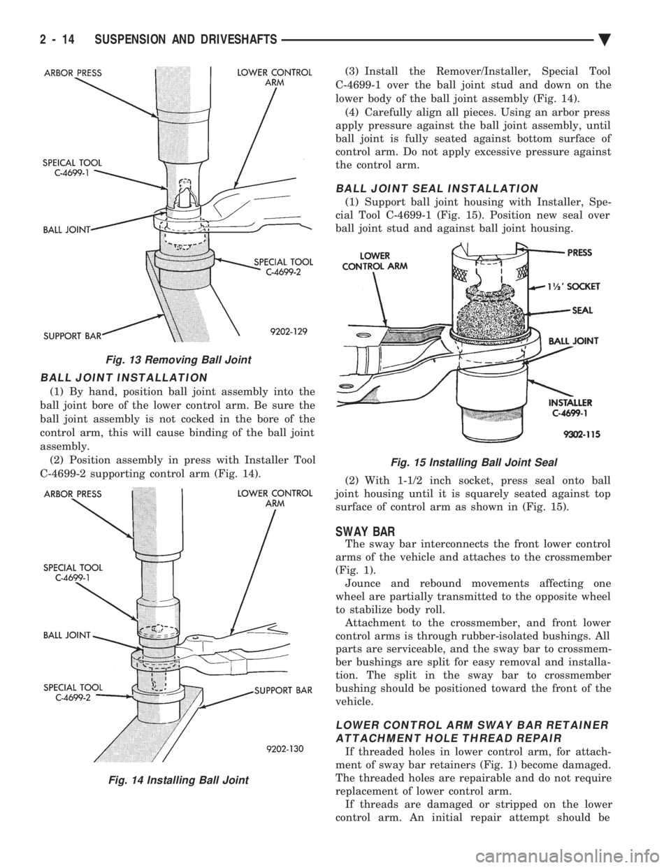
(1) By hand, position ball joint assembly into the
ball joint bore of the lower control arm. Be sure the
ball joint assembly is not cocked in the bore of the
control arm, this will cause binding of the ball joint
assembly. (2) Position assembly in press with Installer Tool
C-4699-2 supporting control arm (Fig. 14). (3) Install the Remover/Installer, Special Tool
C-4699-1 over the ball joint stud and down on the
lower body of the ball joint assembly (Fig. 14). (4) Carefully align all pieces. Using an arbor press
apply pressure against the ball joint assembly, until
ball joint is fully seated against bottom surface of
control arm. Do not apply excessive pressure against
the control arm.
BALL JOINT SEAL INSTALLATION
(1) Support ball joint housing with Installer, Spe-
cial Tool C-4699-1 (Fig. 15). Position new seal over
ball joint stud and against ball joint housing.
(2) With 1-1/2 inch socket, press seal onto ball
joint housing until it is squarely seated against top
surface of control arm as shown in (Fig. 15).
SWAY BAR
The sway bar interconnects the front lower control
arms of the vehicle and attaches to the crossmember
(Fig. 1). Jounce and rebound movements affecting one
wheel are partially transmitted to the opposite wheel
to stabilize body roll. Attachment to the crossmember, and front lower
control arms is through rubber-isolated bushings. All
parts are serviceable, and the sway bar to crossmem-
ber bushings are split for easy removal and installa-
tion. The split in the sway bar to crossmember
bushing should be positioned toward the front of the
vehicle.
LOWER CONTROL ARM SWAY BAR RETAINER ATTACHMENT HOLE THREAD REPAIR
If threaded holes in lower control arm, for attach-
ment of sway bar retainers (Fig. 1) become damaged.
The threaded holes are repairable and do not require
replacement of lower control arm. If threads are damaged or stripped on the lower
control arm. An initial repair attempt should be
Fig. 13 Removing Ball Joint
Fig. 14 Installing Ball Joint
Fig. 15 Installing Ball Joint Seal
2 - 14 SUSPENSION AND DRIVESHAFTS Ä
Page 74 of 2438
the lower clamps and bolts. The center offset in the
sway bar should be oriented toward the front of the
vehicle (Fig. 16)(3) Position bushing retainers on lower control arms
and install bolts (Fig. 16). (4) With lower control arms raised to design height,
tighten all retainer attaching bolts to 70 N Im (50 ft.
lbs.) torque. (5) Lower vehicle.
KNUCKLE (FRONT SUSPENSION)
The front suspension knuckle (Fig. 1) provides for
steering control of the vehicle. Supports the brake
caliper and absorbs the loads exerted during vehicle
braking. It also supports the front (driving) hub and
bearing and stub axle assembly. The front suspension knuckle also provides the abil-
ity to align the front wheels of the vehicle. This is done
by allowing for front wheel camber adjustment and the
ability for front tire Toe adjustments The front suspension knuckle is not a serviceable
component. Do not attempt to straighten or repair the
front suspension knuckle in any way. Service repair or replacement of the front (drive) hub
and bearing, can be done with the front suspension
knuckle remaining on the vehicle.
REMOVAL
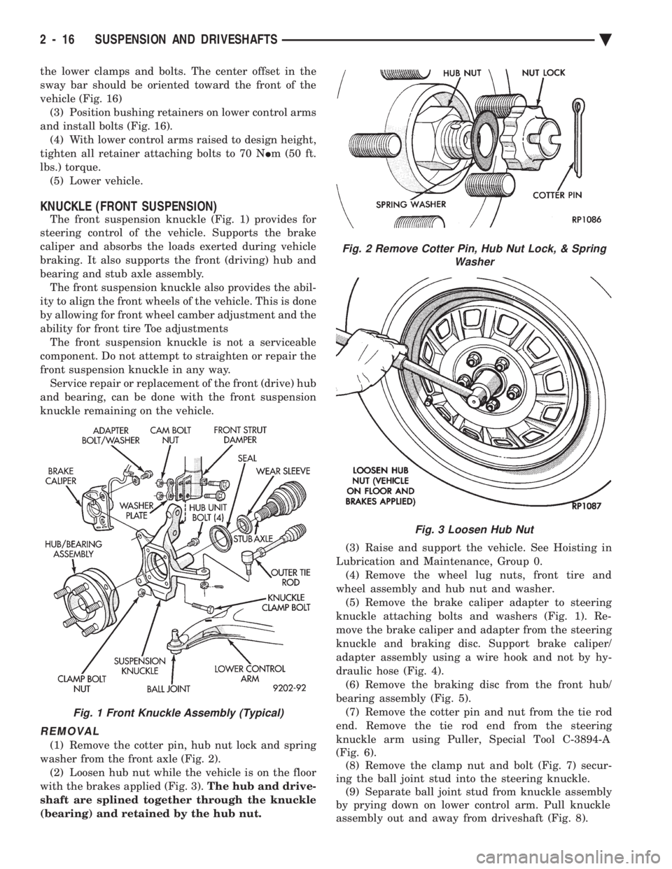
(1) Remove the cotter pin, hub nut lock and spring
washer from the front axle (Fig. 2). (2) Loosen hub nut while the vehicle is on the floor
with the brakes applied (Fig. 3). The hub and drive-
shaft are splined together through the knuckle
(bearing) and retained by the hub nut. (3) Raise and support the vehicle. See Hoisting in
Lubrication and Maintenance, Group 0. (4) Remove the wheel lug nuts, front tire and
wheel assembly and hub nut and washer. (5) Remove the brake caliper adapter to steering
knuckle attaching bolts and washers (Fig. 1). Re-
move the brake caliper and adapter from the steering
knuckle and braking disc. Support brake caliper/
adapter assembly using a wire hook and not by hy-
draulic hose (Fig. 4). (6) Remove the braking disc from the front hub/
bearing assembly (Fig. 5). (7) Remove the cotter pin and nut from the tie rod
end. Remove the tie rod end from the steering
knuckle arm using Puller, Special Tool C-3894-A
(Fig. 6). (8) Remove the clamp nut and bolt (Fig. 7) secur-
ing the ball joint stud into the steering knuckle. (9) Separate ball joint stud from knuckle assembly
by prying down on lower control arm. Pull knuckle
assembly out and away from driveshaft (Fig. 8).
Fig. 2 Remove Cotter Pin, Hub Nut Lock, & Spring Washer
Fig. 3 Loosen Hub Nut
Fig. 1 Front Knuckle Assembly (Typical)
2 - 16 SUSPENSION AND DRIVESHAFTS Ä
Page 77 of 2438
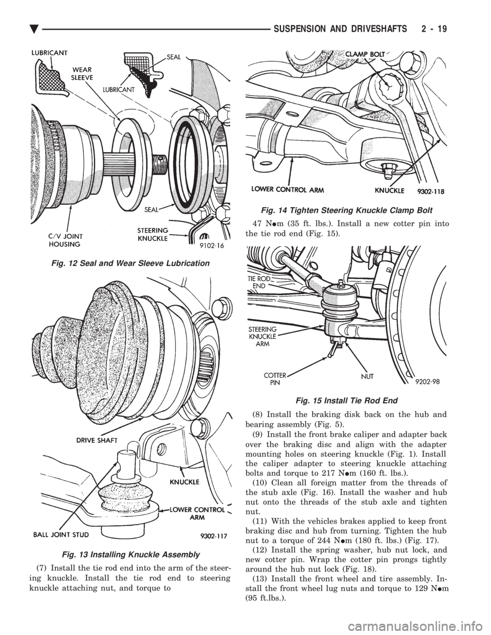
(7) Install the tie rod end into the arm of the steer-
ing knuckle. Install the tie rod end to steering
knuckle attaching nut, and torque to 47 N
Im (35 ft. lbs.). Install a new cotter pin into
the tie rod end (Fig. 15).
(8) Install the braking disk back on the hub and
bearing assembly (Fig. 5). (9) Install the front brake caliper and adapter back
over the braking disc and align with the adapter
mounting holes on steering knuckle (Fig. 1). Install
the caliper adapter to steering knuckle attaching
bolts and torque to 217 N Im (160 ft. lbs.).
(10) Clean all foreign matter from the threads of
the stub axle (Fig. 16). Install the washer and hub
nut onto the threads of the stub axle and tighten
nut. (11) With the vehicles brakes applied to keep front
braking disc and hub from turning. Tighten the hub
nut to a torque of 244 N Im (180 ft. lbs.) (Fig. 17).
(12) Install the spring washer, hub nut lock, and
new cotter pin. Wrap the cotter pin prongs tightly
around the hub nut lock (Fig. 18). (13) Install the front wheel and tire assembly. In-
stall the front wheel lug nuts and torque to 129 N Im
(95 ft.lbs.).
Fig. 13 Installing Knuckle Assembly
Fig. 12 Seal and Wear Sleeve Lubrication
Fig. 14 Tighten Steering Knuckle Clamp Bolt
Fig. 15 Install Tie Rod End
Ä SUSPENSION AND DRIVESHAFTS 2 - 19
Page 78 of 2438
(14) Lower vehicle.
(15) Align the front wheels of the vehicle. Use the
procedure listed under Wheel Alignment, in the
Front Suspension Service Procedures section of this
service manual.
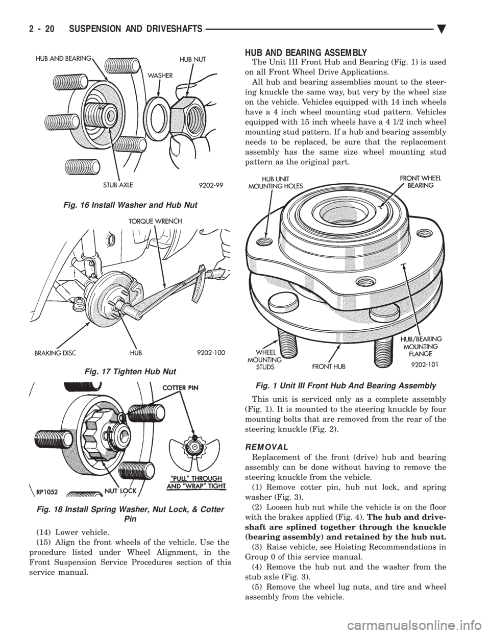
HUB AND BEARING ASSEMBLY
The Unit III Front Hub and Bearing (Fig. 1) is used
on all Front Wheel Drive Applications. All hub and bearing assemblies mount to the steer-
ing knuckle the same way, but very by the wheel size
on the vehicle. Vehicles equipped with 14 inch wheels
have a 4 inch wheel mounting stud pattern. Vehicles
equipped with 15 inch wheels hav e a 4 1/2 inch wheel
mounting stud pattern. If a hub and bearing assembly
needs to be replaced, be sure that the replacement
assembly has the same size wheel mounting stud
pattern as the original part.
This unit is serviced only as a complete assembly
(Fig. 1). It is mounted to the steering knuckle by four
mounting bolts that are removed from the rear of the
steering knuckle (Fig. 2).
REMOVAL
Replacement of the front (drive) hub and bearing
assembly can be done without having to remove the
steering knuckle from the vehicle. (1) Remove cotter pin, hub nut lock, and spring
washer (Fig. 3). (2) Loosen hub nut while the vehicle is on the floor
with the brakes applied (Fig. 4). The hub and drive-
shaft are splined together through the knuckle
(bearing assembly) and retained by the hub nut. (3) Raise vehicle, see Hoisting Recommendations in
Group 0 of this service manual. (4) Remove the hub nut and the washer from the
stub axle (Fig. 3). (5) Remove the wheel lug nuts, and tire and wheel
assembly from the vehicle.
Fig. 16 Install Washer and Hub Nut
Fig. 17 Tighten Hub Nut
Fig. 18 Install Spring Washer, Nut Lock, & Cotter Pin
Fig. 1 Unit III Front Hub And Bearing Assembly
2 - 20 SUSPENSION AND DRIVESHAFTS Ä
Page 82 of 2438
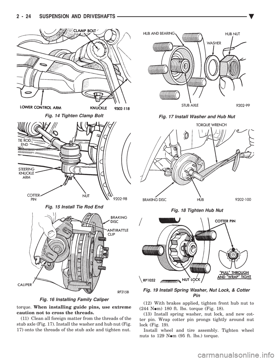
torque. When installing guide pins, use extreme
caution not to cross the threads. (11) Clean all foreign matter from the threads of the
stub axle (Fig. 17). Install the washer and hub nut (Fig.
17) onto the threads of the stub axle and tighten nut. (12) With brakes applied, tighten front hub nut to
(244 N Im) 180 ft. lbs. torque (Fig. 18).
(13) Install spring washer, nut lock, and new cot-
ter pin. Wrap cotter pin prongs tightly around nut
lock (Fig. 19). Install wheel and tire assembly. Tighten wheel
nuts to 129 N Im (95 ft. lbs.) torque.
Fig. 15 Install Tie Rod End
Fig. 16 Installing Family Caliper
Fig. 17 Install Washer and Hub Nut
Fig. 18 Tighten Hub Nut
Fig. 19 Install Spring Washer, Nut Lock, & Cotter
Pin
Fig. 14 Tighten Clamp Bolt
2 - 24 SUSPENSION AND DRIVESHAFTS Ä
Page 83 of 2438
DRIVESHAFTS INDEX
page page
C/V Joint Boots Handling and Cleaning ........ 44
Damper Weights ......................... 48
Driveshaft Identification .................... 27
Driveshaft Positioning Specifications .......... 48
Driveshaft Reconditioning Procedure .......... 31
Driveshafts, Remove Install ................. 27 General Information
....................... 25
Inner C/V Joint .......................... 32
Intermediate Shaft Assembly Recondition ...... 41
Outer C/V Joint .......................... 37
Service Procedures ....................... 27
GENERAL INFORMATION
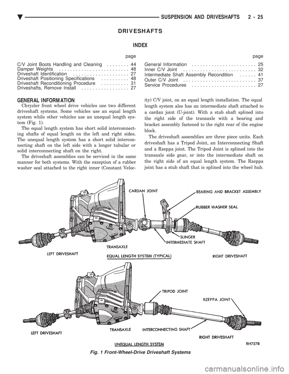
Chrysler front wheel drive vehicles use two different
driveshaft systems. Some vehicles use an equal length
system while other vehicles use an unequal length sys-
tem (Fig. 1). The equal length system has short solid interconnect-
ing shafts of equal length on the left and right sides.
The unequal length system has a short solid intercon-
necting shaft on the left side with a longer tubular or
solid interconnecting shaft on the right.
The driveshaft assemblies can be serviced in the same
manner for both systems. With the exception of a rubber
washer seal attached to the right inner (Constant Veloc- ity) C/V joint, on an equal length installation. The equal
length system also has an intermediate shaft attached to
a cardan joint (U-joint). With a stub shaft splined into
the right side of the transaxle with a bearing and
bracket assembly fastened to the right rear of the engine
block.
The driveshaft assemblies are three piece units. Each
driveshaft has a Tripod Joint, an Interconnecting Shaft
and a Rzeppa joint. The Tripod Joint is splined into the
transaxle side gear, or into the intermediate shaft on
the right side of an equal length system. The Rzeppa
joint has a stub shaft that is splined into the wheel hub.
Fig. 1 Front-Wheel-Drive Driveshaft Systems
Ä SUSPENSION AND DRIVESHAFTS 2 - 25
Page 85 of 2438
DRIVESHAFT IDENTIFICATION
Driveshafts are identified by the manufacturer. Vehi-
cles can be equipped with any of these driveshaft as-
semblies. Each assembly can be identified as shown in
(Fig. 2).
SERVICE PROCEDURES
Procedures for the removal and installation of the
driveshafts are essentially the same for all front
wheel drive vehicles. Each driveshaft has a spring
within the inboard Tripod C/V joint that maintains
constant engagement with the transaxle. This allows
the drive shaft to be removed without dismantling
part of the transaxle.
CAUTION: Boot sealing is vital to retain special lu-
bricants and to prevent foreign contaminants from
entering the C/V joint. Mishandling, such as allow-
ing the assemblies to dangle unsupported, pulling
or pushing the ends can cut boots or damage C/V
joints. During removal and installation procedures
always support both ends of the driveshaft to pre-
vent damage.
DRIVESHAFTS, REMOVE INSTALL
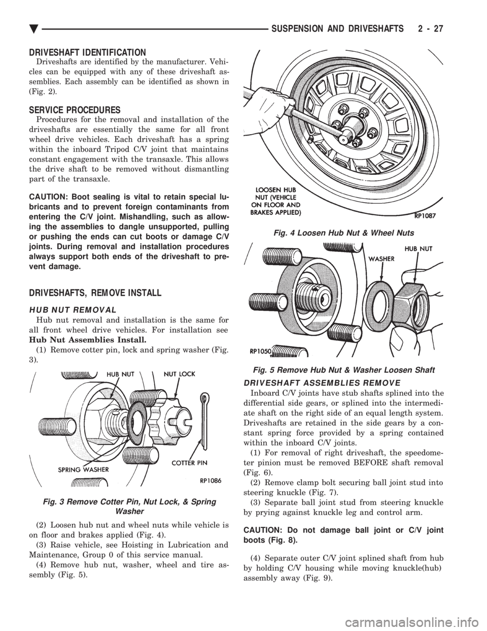
HUB NUT REMOVAL
Hub nut removal and installation is the same for
all front wheel drive vehicles. For installation see
Hub Nut Assemblies Install. (1) Remove cotter pin, lock and spring washer (Fig.
3).
(2) Loosen hub nut and wheel nuts while vehicle is
on floor and brakes applied (Fig. 4). (3) Raise vehicle, see Hoisting in Lubrication and
Maintenance, Group 0 of this service manual. (4) Remove hub nut, washer, wheel and tire as-
sembly (Fig. 5).
DRIVESHAFT ASSEMBLIES REMOVE
Inboard C/V joints have stub shafts splined into the
differential side gears, or splined into the intermedi-
ate shaft on the right side of an equal length system.
Driveshafts are retained in the side gears by a con-
stant spring force provided by a spring contained
within the inboard C/V joints. (1) For removal of right driveshaft, the speedome-
ter pinion must be removed BEFORE shaft removal
(Fig. 6). (2) Remove clamp bolt securing ball joint stud into
steering knuckle (Fig. 7). (3) Separate ball joint stud from steering knuckle
by prying against knuckle leg and control arm.
CAUTION: Do not damage ball joint or C/V joint
boots (Fig. 8). (4) Separate outer C/V joint splined shaft from hub
by holding C/V housing while moving knuckle(hub)
assembly away (Fig. 9).
Fig. 3 Remove Cotter Pin, Nut Lock, & Spring Washer
Fig. 4 Loosen Hub Nut & Wheel Nuts
Fig. 5 Remove Hub Nut & Washer Loosen Shaft
Ä SUSPENSION AND DRIVESHAFTS 2 - 27