1993 CHEVROLET DYNASTY wheel
[x] Cancel search: wheelPage 55 of 2438
CHASSIS AND BODY INDEX
page page
Body Lubrication ......................... 22
Brakes ................................ 21
Headlamps ............................. 22
Lower Ball Joints ......................... 19 Power Steering
.......................... 19
Rear Wheel Bearings ..................... 20
Steering Linkage ......................... 19
STEERING LINKAGE
INSPECTION
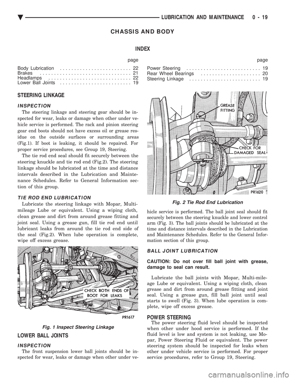
The steering linkage and steering gear should be in-
spected for wear, leaks or damage when other under ve-
hicle service is performed. The rack and pinion steering
gear end boots should not have excess oil or grease res-
idue on the outside surfaces or surrounding areas
(Fig.1). If boot is leaking, it should be repaired. For
proper service procedures, see Group 19, Steering.
The tie rod end seal should fit securely between the
steering knuckle and tie rod end (Fig.2). The steering
linkage should be lubricated at the time and distance
intervals described in the Lubrication and Mainte-
nance Schedules. Refer to General Information sec-
tion of this group.
TIE ROD END LUBRICATION
Lubricate the steering linkage with Mopar, Multi-
mileage Lube or equivalent. Using a wiping cloth,
clean grease and dirt from around grease fitting and
joint seal. Using a grease gun, fill tie rod end until
lubricant leaks from around the tie rod end side of
the seal (Fig.2). When lube operation is complete,
wipe off excess grease.
LOWER BALL JOINTS
INSPECTION
The front suspension lower ball joints should be in-
spected for wear, leaks or damage when other under ve- hicle service is performed. The ball joint seal should fit
securely between the steering knuckle and lower control
arm (Fig. 3). The ball joints should be lubricated at the
time and distance intervals described in the Lubrication
and Maintenance Schedules. Refer to the General Infor-
mation section of this group.
BALL JOINT LUBRICATION
CAUTION: Do not over fill ball joint with grease,
damage to seal can result.
Lubricate the ball joints with Mopar, Multi-mile-
age Lube or equivalent. Using a wiping cloth, clean
grease and dirt from around grease fitting and joint
seal. Using a grease gun, fill ball joint until seal
starts to swell (Fig. 3). When lube operation is com-
plete, wipe off excess grease.
POWER STEERING
The power steering fluid level should be inspected
when other under hood service is performed. If the
fluid level is low and system is not leaking, use Mo-
par, Power Steering Fluid or equivalent. The power
steering system should be inspected for leaks when
other under vehicle service is performed. For proper
service procedures, refer to Group 19, Steering.Fig. 1 Inspect Steering Linkage
Fig. 2 Tie Rod End Lubrication
Ä LUBRICATION AND MAINTENANCE 0 - 19
Page 56 of 2438
The power steering pump drive belt should be in-
spected at the time and distance interval described in
the Lubrication and Maintenance Schedules. Refer to
the General Information section of this group.
POWER STEERING FLUID INSPECTION
WARNING: ENGINE MUST NOT BE RUNNING WHEN
INSPECTING POWER STEERING FLUID LEVEL,
PERSONAL INJURY CAN RESULT.
CAUTION: Do not over fill power steering reservoir
when adding fluid, seal damage and leakage can re-
sult.
TO INSPECT FLUID LEVEL:
(1) Position vehicle on a level surface with engine
at normal running temperature. (2) Turn OFF engine and remove ignition key.
(3) Using a wiping cloth, clean oil and dirt residue
from around power steering reservoir cap. (4) Remove reservoir cap or dipstick and wipe off
fluid. (5) Install cap or dipstick.
(6) Remove cap or dipstick. Holding handle or cap
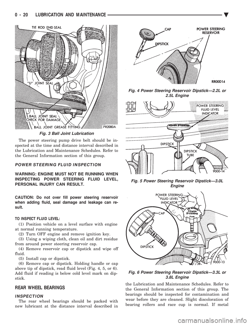
above tip of dipstick, read fluid level (Fig. 4, 5, or 6).
Add fluid if reading is below cold level mark on dip-
stick.
REAR WHEEL BEARINGS
INSPECTION
The rear wheel bearings should be packed with
new lubricant at the distance interval described in the Lubrication and Maintenance Schedules. Refer to
the General Information section of this group. The
bearings should be inspected for contamination and
wear before they are cleaned. Slight discoloration of
bearing rollers and race cup is normal. If metal
Fig. 3 Ball Joint Lubrication
Fig. 4 Power Steering Reservoir DipstickÐ2.2L or 2.5L Engine
Fig. 5 Power Steering Reservoir DipstickÐ3.0L Engine
Fig. 6 Power Steering Reservoir DipstickÐ3.3L or3.8L Engine
0 - 20 LUBRICATION AND MAINTENANCE Ä
Page 57 of 2438
flakes are visible in the used lubricant or the bearing
rollers and race cup is discolored, the bearing and
race cup should be replaced. For proper service pro-
cedures, see Group 5, Brakes. Replace the inner seal
whenever the wheel bearings are serviced.
REAR WHEEL BEARING LUBRICATION
CAUTION: Combining two types of lubricant can
cause bearing failure. Wash used or new bearings
with a suitable solvent and blot dry with a lint free
cloth before packing with new lubricant.
WARNING: DO NOT ALLOW BEARING TO SPIN AT
HIGH RPM WHEN USING COMPRESSED AIR TO
BLOW CLEANING SOLVENT FROM BEARING.
BEARING CAGE CAN EXPLODE, CAUSING PER-
SONAL INJURY.
TO LUBRICATE REAR WHEEL BEARINGS:
(1) Hoist rear wheels off the ground and support ve-
hicle on safety stands. Refer to Hoisting Recommenda-
tions in the General Information section of this group.
(2) Remove rear wheels.
(3) Remove brake caliper on vehicles with rear disc
brakes. For proper procedure, see Group 5, Brakes. (4) Remove rear wheel hub (drum) assembly and
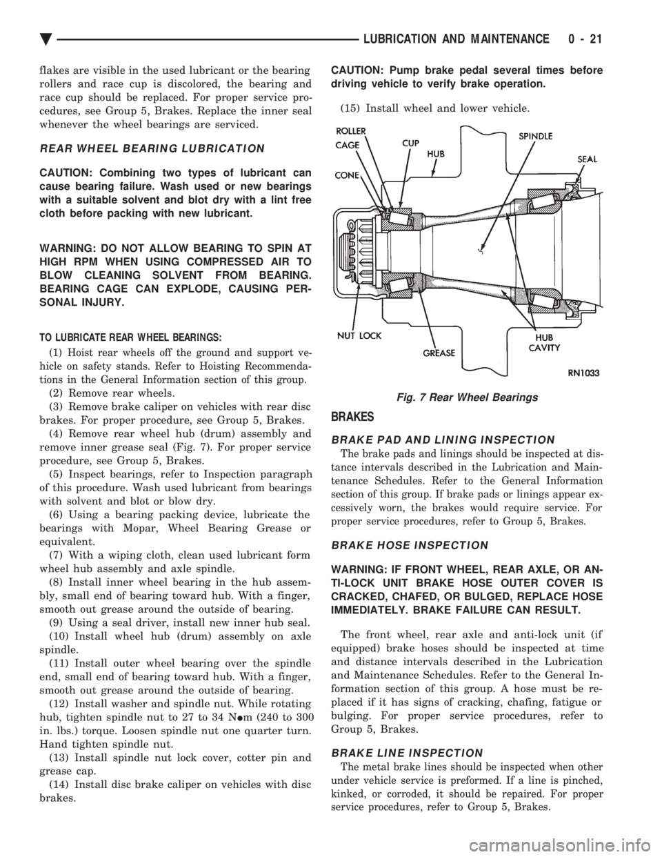
remove inner grease seal (Fig. 7). For proper service
procedure, see Group 5, Brakes. (5) Inspect bearings, refer to Inspection paragraph
of this procedure. Wash used lubricant from bearings
with solvent and blot or blow dry. (6) Using a bearing packing device, lubricate the
bearings with Mopar, Wheel Bearing Grease or
equivalent. (7) With a wiping cloth, clean used lubricant form
wheel hub assembly and axle spindle. (8) Install inner wheel bearing in the hub assem-
bly, small end of bearing toward hub. With a finger,
smooth out grease around the outside of bearing. (9) Using a seal driver, install new inner hub seal.
(10) Install wheel hub (drum) assembly on axle
spindle. (11) Install outer wheel bearing over the spindle
end, small end of bearing toward hub. With a finger,
smooth out grease around the outside of bearing. (12) Install washer and spindle nut. While rotating
hub, tighten spindle nut to 27 to 34 N Im (240 to 300
in. lbs.) torque. Loosen spindle nut one quarter turn.
Hand tighten spindle nut. (13) Install spindle nut lock cover, cotter pin and
grease cap. (14) Install disc brake caliper on vehicles with disc
brakes. CAUTION: Pump brake pedal several times before
driving vehicle to verify brake operation.
(15) Install wheel and lower vehicle.
BRAKES
BRAKE PAD AND LINING INSPECTION
The brake pads and linings should be inspected at dis-
tance intervals described in the Lubrication and Main-
tenance Schedules. Refer to the General Information
section of this group. If brake pads or linings appear ex-
cessively worn, the brakes would require service. For
proper service procedures, refer to Group 5, Brakes.
BRAKE HOSE INSPECTION
WARNING: IF FRONT WHEEL, REAR AXLE, OR AN-
TI-LOCK UNIT BRAKE HOSE OUTER COVER IS
CRACKED, CHAFED, OR BULGED, REPLACE HOSE
IMMEDIATELY. BRAKE FAILURE CAN RESULT.
The front wheel, rear axle and anti-lock unit (if
equipped) brake hoses should be inspected at time
and distance intervals described in the Lubrication
and Maintenance Schedules. Refer to the General In-
formation section of this group. A hose must be re-
placed if it has signs of cracking, chafing, fatigue or
bulging. For proper service procedures, refer to
Group 5, Brakes.
BRAKE LINE INSPECTION
The metal brake lines should be inspected when other
under vehicle service is preformed. If a line is pinched,
kinked, or corroded, it should be repaired. For proper
service procedures, refer to Group 5, Brakes.
Fig. 7 Rear Wheel Bearings
Ä LUBRICATION AND MAINTENANCE 0 - 21
Page 60 of 2438
FRONT SUSPENSION
FRONT SUSPENSION MAJOR COMPONENTS (FIG. 2)
STRUT SUPPORT
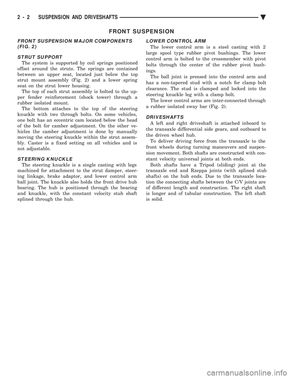
The system is supported by coil springs positioned
offset around the struts. The springs are contained
between an upper seat, located just below the top
strut mount assembly (Fig. 2) and a lower spring
seat on the strut lower housing. The top of each strut assembly is bolted to the up-
per fender reinforcement (shock tower) through a
rubber isolated mount. The bottom attaches to the top of the steering
knuckle with two through bolts. On some vehicles,
one bolt has an eccentric cam located below the head
of the bolt for camber adjustment. On the other ve-
hicles the camber adjustment is done by manually
moving the steering knuckle within the strut assem-
bly. Caster is a fixed setting on all vehicles and is
not adjustable.
STEERING KNUCKLE
The steering knuckle is a single casting with legs
machined for attachment to the strut damper, steer-
ing linkage, brake adaptor, and lower control arm
ball joint. The knuckle also holds the front drive hub
bearing. The hub is positioned through the bearing
and knuckle, with the constant velocity stub shaft
splined through the hub.
LOWER CONTROL ARM
The lower control arm is a steel casting with 2
large spool type rubber pivot bushings. The lower
control arm is bolted to the crossmember with pivot
bolts through the center of the rubber pivot bush-
ings. The ball joint is pressed into the control arm and
has a non-tapered stud with a notch for clamp bolt
clearance. The stud is clamped and locked into the
steering knuckle leg with a clamp bolt. The lower control arms are inter-connected through
a rubber isolated sway bar (Fig. 2).
DRIVESHAFTS
A left and right driveshaft is attached inboard to
the transaxle differential side gears, and outboard to
the driven wheel hub. To deliver driving force from the transaxle to the
front wheels during turning maneuvers and suspen-
sion movement. Both shafts are constructed with con-
stant velocity universal joints at both ends. Both shafts have a Tripod (sliding) joint at the
transaxle end and Rzeppa joints (with splined stub
shafts) on the hub ends. Due to the transaxle loca-
tion the connecting shafts between the C/V joints are
of different length and construction. The right shaft
is longer and of tubular construction. The left shaft
is solid.
2 - 2 SUSPENSION AND DRIVESHAFTS Ä
Page 62 of 2438
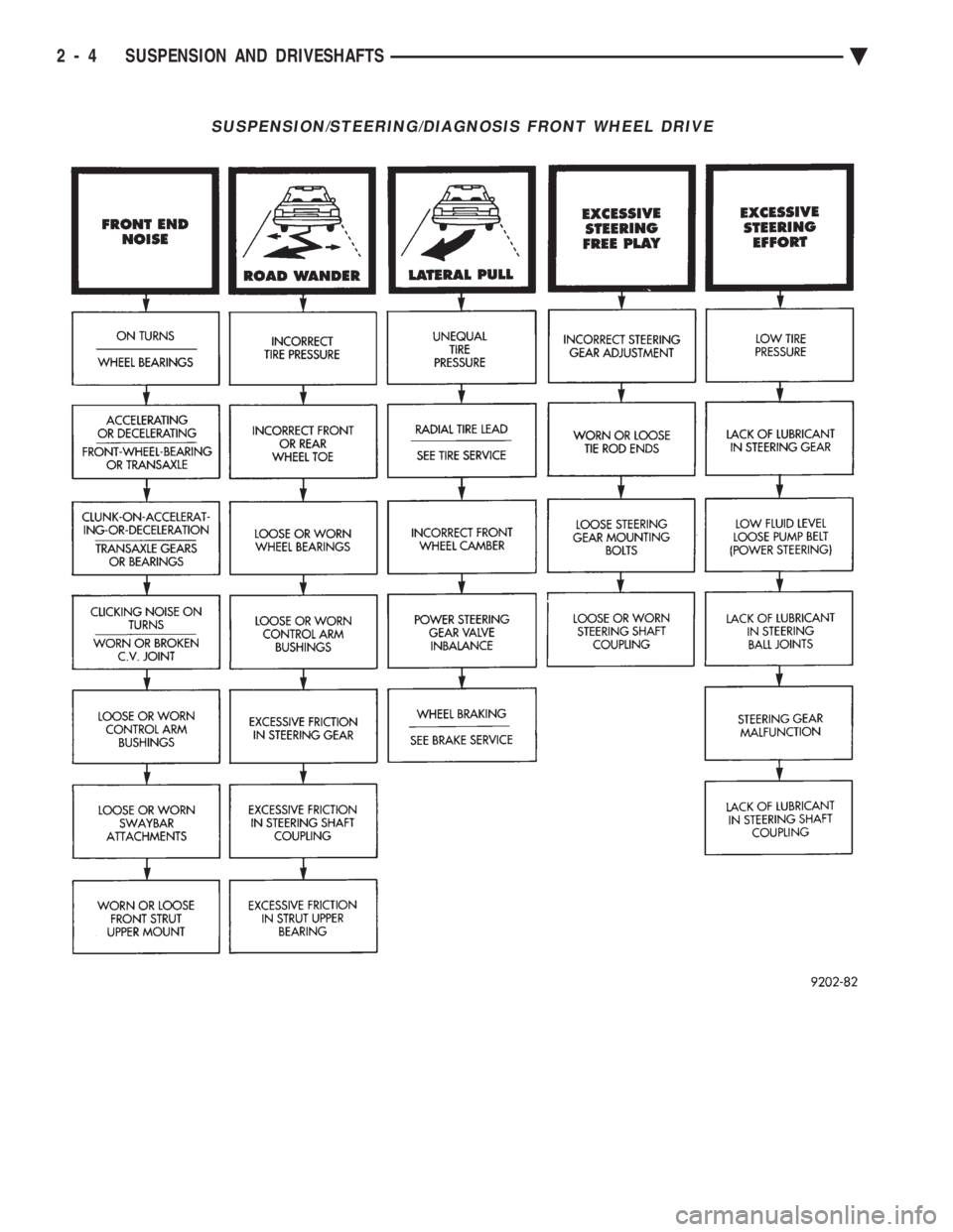
SUSPENSION/STEERING/DIAGNOSIS FRONT WHEEL DRIVE
2 - 4 SUSPENSION AND DRIVESHAFTS Ä
Page 63 of 2438
FRONT SUSPENSION SERVICE PROCEDURES INDEX
page page
Ball Joints .............................. 13
Hub and Bearing Assembly ................. 20
Knuckle (Front Suspension) ................. 16
Lower Control Arm ....................... 10
Lower Control Arm Pivot Bushings ........... 11 Shock Absorbers (Strut Damper)
............. 10
Strut Damper Assembly ..................... 7
Suspension Coil Springs .................... 9
Sway Bar .............................. 14
Wheel Alignment .......................... 5
WHEEL ALIGNMENT
Front wheel alignment is the proper adjustment of
all interrelated front suspension angles. These angles
are what affects the running and steering of the
front wheels of the vehicle. The method of checking front alignment will vary
depending on the type of equipment being used. The
instructions furnished by the manufacturer of the
equipment should always be followed. With the ex-
ception that the alignment specifications recom-
mended by Chrysler Corporation be used. There are six basic factors which are the founda-
tion to front wheel alignment. These are height,
caster, camber, toe-in, steering axis inclination and
toe-out on turns. Of the six basic factors only camber
and toe in are mechanically adjustable (Fig. 1)
CAUTION: Do not attempt to modify any suspen-
sion or steering components by heating or bending
of the component.
Wheel alignment adjustments and checks should be
made in the following sequence. (1) Camber
(2) Toe
Camber is the number of degrees the top of the
wheel is tilted inward or outward from true vertical.
Inward tilt is negative camber. Outward tilt is posi-
tive camber. Excessive camber is a tire wear factor: negative
camber causes wear on the inside of the tire, while
positive camber causes wear to the outside. Toe
is measured in degrees or inches and is the
distance the front edges of the tires are closer (or far-
ther apart) than the rear edges. See Front Wheel
Drive Specifications for Toesettings.
PRE-ALIGNMENT
Before any attempt is made to change or correct
the wheel alignment factors. The following inspection
and necessary corrections must be made on those
parts which influence the steering of the vehicle. (1) Check and inflate tires to recommended pres-
sure. All tires should be the same size and in good
condition and have approximately the same wear.
Note type of tread wear which will aid in diagnosing,
see Wheels and Tires, Group 22. (2) Check front wheel and tire assembly for radial
runout. (3) Inspect lower ball joints and all steering link-
age for looseness. (4) Check for broken or sagged front and rear
springs. Front suspension must only be checked after the
vehicle has had the following checked or adjusted.
Tires set to recommended pressures, full tank of fuel,
no passenger or luggage compartment load and is on
a level floor or alignment rack. Just prior to each alignment reading. The vehicle
should be bounced (rear first, then front) by grasping
bumper at center and jouncing each end an equal
number of times. Always release bumpers at bottom
of down cycle.
Ä SUSPENSION AND DRIVESHAFTS 2 - 5
Page 65 of 2438
WHEEL ALIGNMENT SERVICE PROCEDURE
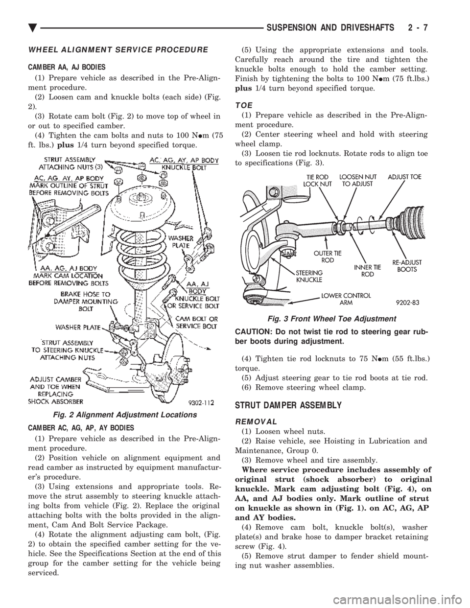
CAMBER AA, AJ BODIES (1) Prepare vehicle as described in the Pre-Align-
ment procedure. (2) Loosen cam and knuckle bolts (each side) (Fig.
2). (3) Rotate cam bolt (Fig. 2) to move top of wheel in
or out to specified camber. (4) Tighten the cam bolts and nuts to 100 N Im (75
ft. lbs.) plus1/4 turn beyond specified torque.
CAMBER AC, AG, AP, AY BODIES (1) Prepare vehicle as described in the Pre-Align-
ment procedure. (2) Position vehicle on alignment equipment and
read camber as instructed by equipment manufactur-
er's procedure. (3) Using extensions and appropriate tools. Re-
move the strut assembly to steering knuckle attach-
ing bolts from vehicle (Fig. 2). Replace the original
attaching bolts with the bolts provided in the align-
ment, Cam And Bolt Service Package. (4) Rotate the alignment adjusting cam bolt, (Fig.
2) to obtain the specified camber setting for the ve-
hicle. See the Specifications Section at the end of this
group for the camber setting for the vehicle being
serviced. (5) Using the appropriate extensions and tools.
Carefully reach around the tire and tighten the
knuckle bolts enough to hold the camber setting.
Finish by tightening the bolts to 100 N Im (75 ft.lbs.)
plus 1/4 turn beyond specified torque.
TOE
(1) Prepare vehicle as described in the Pre-Align-
ment procedure. (2) Center steering wheel and hold with steering
wheel clamp. (3) Loosen tie rod locknuts. Rotate rods to align toe
to specifications (Fig. 3).
CAUTION: Do not twist tie rod to steering gear rub-
ber boots during adjustment. (4) Tighten tie rod locknuts to 75 N Im (55 ft.lbs.)
torque. (5) Adjust steering gear to tie rod boots at tie rod.
(6) Remove steering wheel clamp.
STRUT DAMPER ASSEMBLY
REMOVAL
(1) Loosen wheel nuts.
(2) Raise vehicle, see Hoisting in Lubrication and
Maintenance, Group 0. (3) Remove wheel and tire assembly.
Where service procedure includes assembly of
original strut (shock absorber) to original
knuckle. Mark cam adjusting bolt (Fig. 4), on
AA, and AJ bodies only. Mark outline of strut
on knuckle as shown in (Fig. 1). on AC, AG, AP
and AY bodies. (4) Remove cam bolt, knuckle bolt(s), washer
plate(s) and brake hose to damper bracket retaining
screw (Fig. 4). (5) Remove strut damper to fender shield mount-
ing nut washer assemblies.
Fig. 2 Alignment Adjustment Locations
Fig. 3 Front Wheel Toe Adjustment
Ä SUSPENSION AND DRIVESHAFTS 2 - 7
Page 66 of 2438
INSPECTION
Inspect for evidence of fluid running from the up-
per end of the reservoir. (Actual leakage will be a
stream of fluid running down the side and dripping
off lower end of unit). A slight amount of seepage be-
tween the strut rod and strut shaft seal is not un-
usual and does not affect performance of the strut
assembly.
INSTALLATION
(1) Install unit into fender reinforcement and in-
stall retaining nuts and washer assemblies (Fig. 1).
Tighten the 3 nuts to 27 N Im (20 ft. lbs.) torque.
(2) Position steering knuckle neck into strut as-
sembly. Position washer plate and install cam and
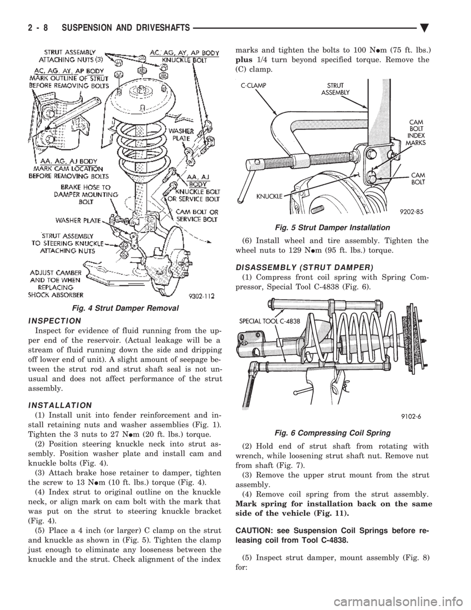
knuckle bolts (Fig. 4). (3) Attach brake hose retainer to damper, tighten
the screw to 13 N Im (10 ft. lbs.) torque (Fig. 4).
(4) Index strut to original outline on the knuckle
neck, or align mark on cam bolt with the mark that
was put on the strut to steering knuckle bracket
(Fig. 4). (5) Plac e a 4 inch (or larger) C clamp on the strut
and knuckle as shown in (Fig. 5). Tighten the clamp
just enough to eliminate any looseness between the
knuckle and the strut. Check alignment of the index marks and tighten the bolts to 100 N
Im (75 ft. lbs.)
plus 1/4 turn beyond specified torque. Remove the
(C) clamp.
(6) Install wheel and tire assembly. Tighten the
wheel nuts to 129 N Im (95 ft. lbs.) torque.
DISASSEMBLY (STRUT DAMPER)
(1) Compress front coil spring with Spring Com-
pressor, Special Tool C-4838 (Fig. 6).
(2) Hold end of strut shaft from rotating with
wrench, while loosening strut shaft nut. Remove nut
from shaft (Fig. 7). (3) Remove the upper strut mount from the strut
assembly. (4) Remove coil spring from the strut assembly.
Mark spring for installation back on the same
side of the vehicle (Fig. 11).
CAUTION: see Suspension Coil Springs before re-
leasing coil from Tool C-4838.
(5) Inspect strut damper, mount assembly (Fig. 8)
for:
Fig. 4 Strut Damper Removal
Fig. 5 Strut Damper Installation
Fig. 6 Compressing Coil Spring
2 - 8 SUSPENSION AND DRIVESHAFTS Ä