1993 CHEVROLET DYNASTY oil
[x] Cancel search: oilPage 2100 of 2438
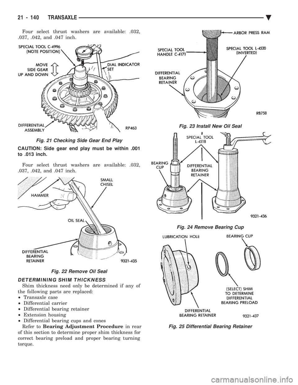
Four select thrust washers are available: .032,
.037, .042, and .047 inch.
CAUTION: Side gear end play must be within .001
to .013 inch.
Four select thrust washers are available: .032,
.037, .042, and .047 inch.
DETERMINING SHIM THICKNESS
Shim thickness need only be determined if any of
the following parts are replaced:
² Transaxle case
² Differential carrier
² Differential bearing retainer
² Extension housing
² Differential bearing cups and cones
Refer to Bearing Adjustment Procedure in rear
of this section to determine proper shim thickness for
correct bearing preload and proper bearing turning
torque.
Fig. 21 Checking Side Gear End Play
Fig. 22 Remove Oil Seal
Fig. 23 Install New Oil Seal
Fig. 24 Remove Bearing Cup
Fig. 25 Differential Bearing Retainer
21 - 140 TRANSAXLE Ä
Page 2101 of 2438
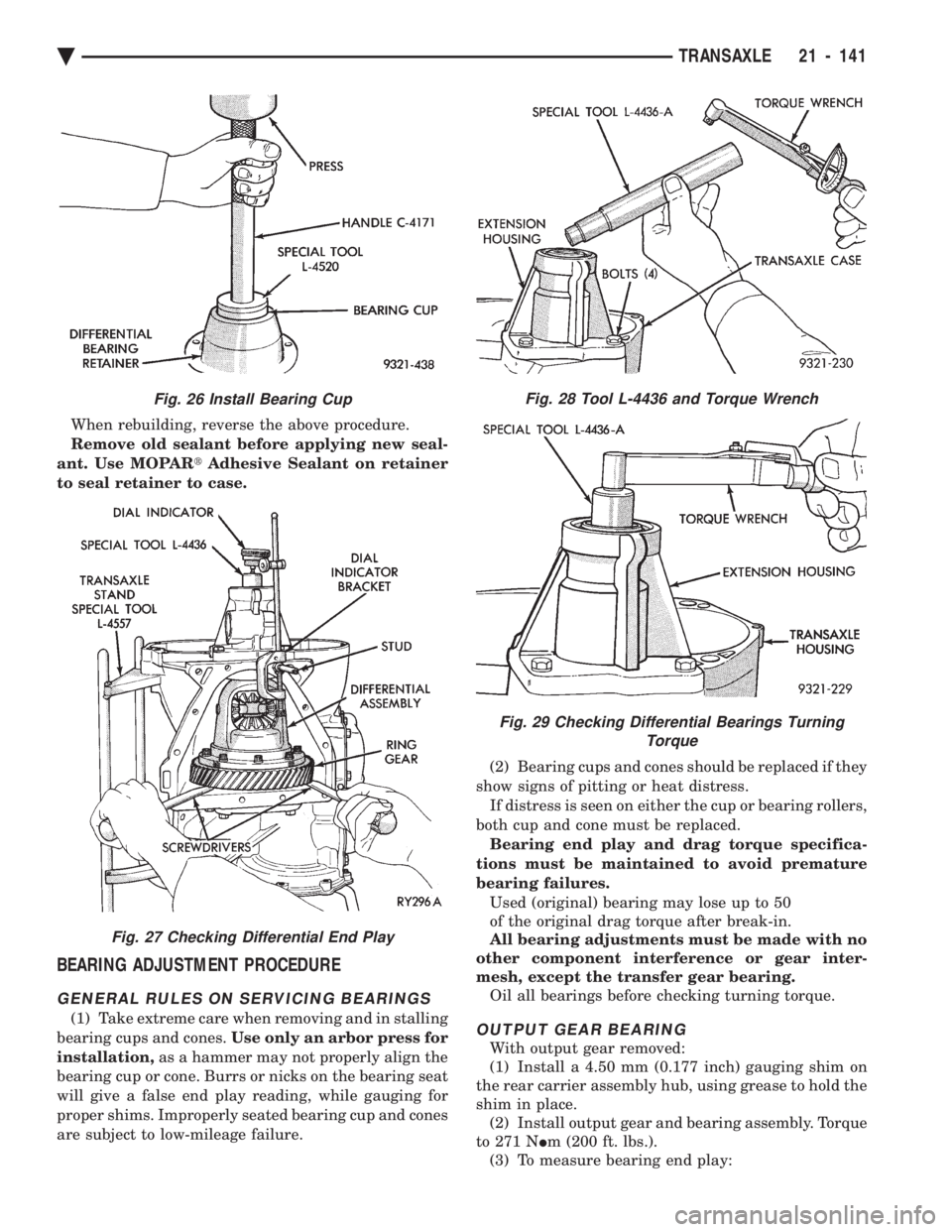
When rebuilding, reverse the above procedure.
Remove old sealant before applying new seal-
ant. Use MOPAR tAdhesive Sealant on retainer
to seal retainer to case.
BEARING ADJUSTMENT PROCEDURE
GENERAL RULES ON SERVICING BEARINGS
(1) Take extreme care when removing and in stalling
bearing cups and cones. Use only an arbor press for
installation, as a hammer may not properly align the
bearing cup or cone. Burrs or nicks on the bearing seat
will give a false end play reading, while gauging for
proper shims. Improperly seated bearing cup and cones
are subject to low-mileage failure. (2) Bearing cups and cones should be replaced if they
show signs of pitting or heat distress. If distress is seen on either the cup or bearing rollers,
both cup and cone must be replaced. Bearing end play and drag torque specifica-
tions must be maintained to avoid premature
bearing failures. Used (original) bearing may lose up to 50
of the original drag torque after break-in.
All bearing adjustments must be made with no
other component interference or gear inter-
mesh, except the transfer gear bearing. Oil all bearings before checking turning torque.OUTPUT GEAR BEARING
With output gear removed:
(1) Install a 4.50 mm (0.177 inch) gauging shim on
the rear carrier assembly hub, using grease to hold the
shim in place. (2) Install output gear and bearing assembly. Torque
to 271 N Im (200 ft. lbs.).
(3) To measure bearing end play:
Fig. 26 Install Bearing Cup
Fig. 27 Checking Differential End Play
Fig. 28 Tool L-4436 and Torque Wrench
Fig. 29 Checking Differential Bearings Turning Torque
Ä TRANSAXLE 21 - 141
Page 2102 of 2438
(a) Attach Tool L-4432 to the gear.
(b) Push and pull the gear while rotating back
and forth to insure seating of the bearing rollers. (c) Using a dial indicator, mounted to the tran-
saxle case, measure output gear end play.
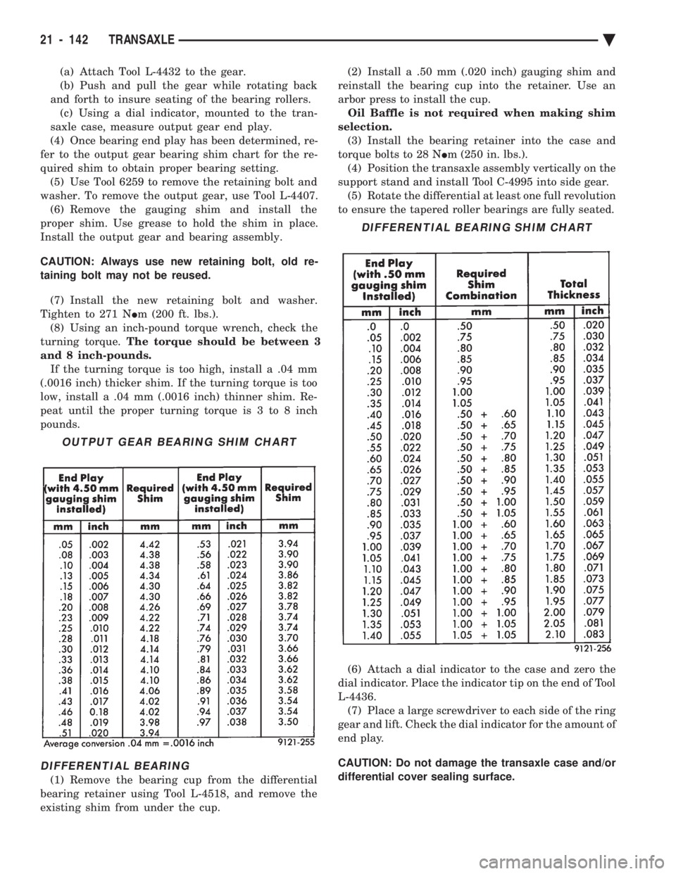
(4) Once bearing end play has been determined, re-
fer to the output gear bearing shim chart for the re-
quired shim to obtain proper bearing setting. (5) Use Tool 6259 to remove the retaining bolt and
washer. To remove the output gear, use Tool L-4407. (6) Remove the gauging shim and install the
proper shim. Use grease to hold the shim in place.
Install the output gear and bearing assembly.
CAUTION: Always use new retaining bolt, old re-
taining bolt may not be reused.
(7) Install the new retaining bolt and washer.
Tighten to 271 N Im (200 ft. lbs.).
(8) Using an inch-pound torque wrench, check the
turning torque. The torque should be between 3
and 8 inch-pounds. If the turning torque is too high, install a .04 mm
(.0016 inch) thicker shim. If the turning torque is too
low, install a .04 mm (.0016 inch) thinner shim. Re-
peat until the proper turning torque is 3 to 8 inch
pounds.
DIFFERENTIAL BEARING
(1) Remove the bearing cup from the differential
bearing retainer using Tool L-4518, and remove the
existing shim from under the cup. (2) Install a .50 mm (.020 inch) gauging shim and
reinstall the bearing cup into the retainer. Use an
arbor press to install the cup. Oil Baffle is not required when making shim
selection. (3) Install the bearing retainer into the case and
torque bolts to 28 N Im (250 in. lbs.).
(4) Position the transaxle assembly vertically on the
support stand and install Tool C-4995 into side gear. (5) Rotate the differential at least one full revolution
to ensure the tapered roller bearings are fully seated.
(6) Attach a dial indicator to the case and zero the
dial indicator. Place the indicator tip on the end of Tool
L-4436. (7) Place a large screwdriver to each side of the ring
gear and lift. Check the dial indicator for the amount of
end play.
CAUTION: Do not damage the transaxle case and/or
differential cover sealing surface.
OUTPUT GEAR BEARING SHIM CHART
DIFFERENTIAL BEARING SHIM CHART
21 - 142 TRANSAXLE Ä
Page 2103 of 2438
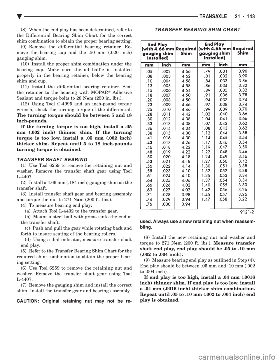
(8) When the end play has been determined, refer to
the Differential Bearing Shim Chart for the correct
shim combination to obtain the proper bearing setting. (9) Remove the differential bearing retainer. Re-
move the bearing cup and the .50 mm (.020 inch)
gauging shim. (10) Install the proper shim combination under the
bearing cup. Make sure the oil baffle is installed
properly in the bearing retainer, below the bearing
shim and cup. (11) Install the differential bearing retainer. Seal
the retainer to the housing with MOPAR tAdhesive
Sealant and torque bolts to 28 N Im (250 in. lbs.).
(12) Using Tool C-4995 and an inch-pound torque
wrench, check the turning torque of the differential.
The turning torque should be between 5 and 18
inch-pounds. If the turning torque is too high, install a .05
mm (.002 inch) thinner shim. If the turning
torque is too low, install a .05 mm (.002 inch)
thicker shim. Repeat until 5 to 18 inch-pounds
turning torque is obtained.
TRANSFER SHAFT BEARING
(1) Use Tool 6259 to remove the retaining nut and
washer. Remove the transfer shaft gear using Tool
L-4407. (2) Install a 4.66 mm (.184 inch) gauging shim on the
transfer shaft. (3) Install transfer shaft gear and bearing assembly
and torque the nut to 271 N Im (200 ft. lbs.).
(4) To measure bearing end play: (a) Attach Tool L-4432 to the transfer gear.
(b) Mount a steel ball with grease into the end of
the transfer shaft. (c) Push and pull the gear while rotating back and
forth to insure seating of the bearing rollers. (d) Using a dial indicator, measure transfer shaft
end play.
(5) Refer to the Transfer Bearing Shim Chart for the
required shim combination to obtain the proper bear-
ing setting. (6) Use Tool 6259 to remove the retaining nut and
washer. Remove the transfer shaft gear using Tool
L-4407. (7) Remove the gauging shim and install the correct
shim. Install the transfer gear and bearing assembly.
CAUTION: Original retaining nut may not be re- used. Always use a new retaining nut when reassem-
bling.
(8) Install the new retaining nut and washer and
torque to 271 N Im (200 ft. lbs.). Measure transfer
shaft end play, end play should be .05 to .10 mm
(.002 to .004 inch). (9) Measure bearing end play as outlined in Step (4).
End play should be between .05 mm and .10 mm (.002
to .004 inch). If end play is too high, install a .04 mm (.0016
inch) thinner shim. If end play is too low, install
a .04 mm (.0016 inch) thicker shim combination.
Repeat until .05 to .10 mm (.002 to .004 inch) end
play is obtained.
TRANSFER BEARING SHIM CHART
Ä TRANSAXLE 21 - 143
Page 2149 of 2438
WHEELSÐTIRES
CONTENTS
page page
SPECIFICATIONS ........................ 8
TIRE SERVICE PROCEDURES .............. 1 WHEELS SERVICE PROCEDURES
........... 6
TIRE SERVICE PROCEDURES INDEX
page page
Cleaning of Tires .......................... 1
General Information ........................ 1
Pressure Gauges ......................... 2
Radial-Ply Tires ........................... 1
Repairing Leaks .......................... 3
Rotation ................................ 3 Spare TireÐCompact
...................... 1
Tire Inflation Pressures ..................... 2
Tire Noise or Vibration ..................... 3
Tire Wear Patterns ........................ 3
Tread Wear Indicators ...................... 3
GENERAL INFORMATION
Throughout this group, references may be made to a
particular vehicle by letter or number designation. A
chart showing the breakdown of these designations is
included in the Introduction Section. Tires are designed for the vehicle and provide the
best overall performance for normal operation. The
ride and handling characteristics match the vehicle's
requirements. With proper care they will give excellent
reliability traction, skid resistance and tread life. They
have load carrying capacity, when properly inflated, to
operate at loads up to the specified Maximum Vehicle
Capacity. Driving habits have more effect on tire life than any
other factor. Careful drivers will obtain, in most cases,
much greater mileage than severe or careless drivers. A
few of the driving habits which will shorten the life of
any tire are:
² Rapid acceleration and deceleration
² Severe application of brakes
² High-speed driving
² Taking turns at excessive speeds
² Striking curbs and other obstacles
Radial ply tires can be more susceptible to irregular
tread wear. It is very important to follow the tire
rotation interval shown in the section on Tire
Rotation to achieve a greater tread life potential.
RADIAL-PLY TIRES
Radial-ply tires improve handling, tread life, and
ride quality and decrease rolling resistance. Radial-ply tires must always be used in sets of four
and under no circumstances should they be used on
the front only. However, they may be mixed with temporary spare tires when necessary,
but reduced speeds are recommended. Radial-ply tires have the same load carrying capac-
ity as other types of tires of the same size. They also
use the same recommended inflation pressures.
SPARE TIREÐCOMPACT
The compact spare tire is designed for emergency
use only. The original tire should be repaired and re-
installed at the first opportunity. Refer to Owner's
Manual for complete details.
TIRE CHAINS
Tire snow chains may be used on certainmodels.
Refer to Owner's Manual for more information.
CLEANING OF TIRES
Remove protective coating on tires before delivery
of vehicle, otherwise it could cause deterioration of
tires. Remove protective coating by applying warm wa-
ter, letting it soak one minute, and then scrubbing
the coating away with a soft bristle brush. Steam cleaning may also be used for cleaning.
DO NOT use gasoline or wire brush for cleaning.
DO NOT use mineral oil or an oil-based solvent.
Ä WHEELSÐTIRES 22 - 1
Page 2151 of 2438
ponents. Under extremes of suspension and steering
travel tire damage may occur.
WARNING: FAILURE TO EQUIP THE VEHICLE WITH
TIRES HAVING ADEQUATE SPEED RATING CAN
CAUSE SUDDEN TIRE FAILURE.
ROTATION
DIRECTIONAL TREAD PATTERN TIRES
Some vehicles are fitted with special high-perfor-
mance tires having a directional tread pattern de-
signed to improve traction on wet pavement. To obtain the full benefits of this design, the tires
must be installed so that they rotate in the correct
direction. This is indicated by arrows on the tire
sidewalls. When wheels and tires are being installed, extra
care is needed to ensure that this direction of rota-
tion is maintained. Refer to Owner's Manual for rotation schedule.
NONDIRECTIONAL TIRES
Tires on the front and rear axles of vehicles oper-
ate at different loads and perform different steering,
driving, and braking functions. For these reasons,
they wear at unequal rates, and tend to develop ir-
regular wear patterns. These effects can be reduced
by timely rotation of tires. Rotation will increase
tread life, help to maintain mud, snow, and wet trac-
tion levels, and contribute to a smooth, quiet ride. The suggested rotation method is the forward-cross
tire rotation method. This method takes advantage of
current tire industry practice which now allows cross
rotation of radial-ply tires. Refer to the owner's man-
ual (usually found in the glove box) for additional in-
formation. Other rotation methods may be used, but
may not have all the benefits of the recommended
method. Always check air pressure and wheel nut tightness
after rotation. Do NOT use oil or grease on studs
or nuts. Refer to Owner's Manual for rotation schedule.
TREAD WEAR INDICATORS
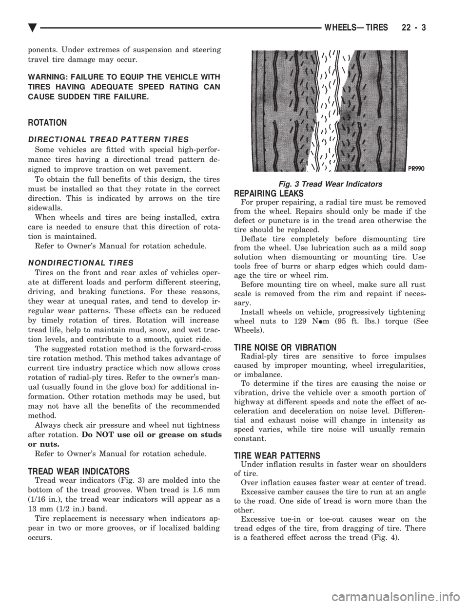
Tread wear indicators (Fig. 3) are molded into the
bottom of the tread grooves. When tread is 1.6 mm
(1/16 in.), the tread wear indicators will appear as a
13 mm (1/2 in.) band. Tire replacement is necessary when indicators ap-
pear in two or more grooves, or if localized balding
occurs.
REPAIRING LEAKS
For proper repairing, a radial tire must be removed
from the wheel. Repairs should only be made if the
defect or puncture is in the tread area otherwise the
tire should be replaced. Deflate tire completely before dismounting tire
from the wheel. Use lubrication such as a mild soap
solution when dismounting or mounting tire. Use
tools free of burrs or sharp edges which could dam-
age the tire or wheel rim. Before mounting tire on wheel, make sure all rust
scale is removed from the rim and repaint if neces-
sary. Install wheels on vehicle, progressively tightening
wheel nuts to 129 N Im (95 ft. lbs.) torque (See
Wheels).
TIRE NOISE OR VIBRATION
Radial-ply tires are sensitive to force impulses
caused by improper mounting, wheel irregularities,
or imbalance. To determine if the tires are causing the noise or
vibration, drive the vehicle over a smooth portion of
highway at different speeds and note the effect of ac-
celeration and deceleration on noise level. Differen-
tial and exhaust noise will change in intensity as
speed varies, while tire noise will usually remain
constant.
TIRE WEAR PATTERNS
Under inflation results in faster wear on shoulders
of tire. Over inflation causes faster wear at center of tread.
Excessive camber causes the tire to run at an angle
to the road. One side of tread is worn more than the
other. Excessive toe-in or toe-out causes wear on the
tread edges of the tire, from dragging of tire. There
is a feathered effect across the tread (Fig. 4).
Fig. 3 Tread Wear Indicators
Ä WHEELSÐTIRES 22 - 3
Page 2154 of 2438
WHEELS SERVICE PROCEDURES INDEX
page page
General Information ........................ 6
Tire and Wheel Balance .................... 6
Tire and Wheel Run Out .................... 7 Wheel Installation
......................... 6
Wheel Replacement ....................... 6
GENERAL INFORMATION
Original equipment wheels are designed for proper
operation at all loads up to the maximum vehicle ca-
pacity. All models use steel or cast aluminum drop center
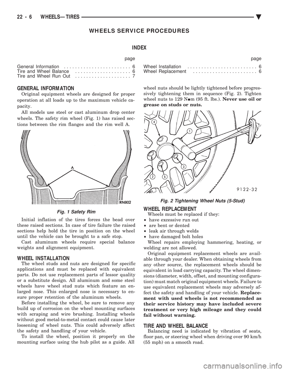
wheels. The safety rim wheel (Fig. 1) has raised sec-
tions between the rim flanges and the rim well A.
Initial inflation of the tires forces the bead over
these raised sections. In case of tire failure the raised
sections help hold the tire in position on the wheel
until the vehicle can be brought to a safe stop. Cast aluminum wheels require special balance
weights and alignment equipment.
WHEEL INSTALLATION
The wheel studs and nuts are designed for specific
applications and must be replaced with equivalent
parts. Do not use replacement parts of lessor quality
or a substitute design. All aluminum and some steel
wheels have wheel stud nuts which feature an en-
larged nose. This enlarged nose is necessary to en-
sure proper retention of the aluminum wheels. Before installing the wheel, be sure to remove any
build up of corrosion on the wheel mounting surfaces
with scraping and wire brushing. Installing wheels
without good metal-to-metal contact could cause later
loosening of wheel nuts. This could adversely affect
the safety and handling of your vehicle. To install the wheel, position it properly on the
mounting surface using the hub pilot as a guide. All wheel nuts should be lightly tightened before progres-
sively tightening them in sequence (Fig. 2). Tighten
wheel nuts to 129 N Im (95 ft. lbs.). Never use oil or
grease on studs or nuts.
WHEEL REPLACEMENT
Wheels must be replaced if they:
² have excessive run out
² are bent or dented
² leak air through welds
² have damaged bolt holes
Wheel repairs employing hammering, heating, or
welding are not allowed. Original equipment replacement wheels are avail-
able through your dealer. When obtaining wheels from
any other source, the replacement wheels should be
equivalent in load carrying capacity. The wheel dimen-
sions (diameter, width, offset, and mounting configura-
tion) must match original equipment wheels. Failure to
use equivalent replacement wheels may adversely af-
fect the safety and handling of your vehicle. Replace-
ment with used wheels is not recommended as
their service history may have included severe
treatment or very high mileage and they could
fail without warning.
TIRE AND WHEEL BALANCE
Balancing need is indicated by vibration of seats,
floor pan, or steering wheel when driving over 90 km/h
(55 mph) on a smooth road.
Fig. 1 Safety Rim
Fig. 2 Tightening Wheel Nuts (5-Stud)
22 - 6 WHEELSÐTIRES Ä
Page 2160 of 2438
PAINT
INTRODUCTION
A paint code is provided on the body code plate
located in the engine compartment. Refer to the Intro-
duction section at the front of this manual for body code
plate description. The color names provided in the
Paint and Trim Code Description chart are the color
names used on most repair product containers. The
color names in the new vehicle ordering guides vary
depending on car line but use the same color code.
BASE COAT/CLEAR COAT FINISH
On most vehicles a two part paint application (base
coat/clear coat) is used. Color paint that is applied to
primer is called base coat. The clear coat protects the
base coat from ultra violet light and provides a durable
high gloss finish.
WET SANDING,BUFFING AND POLISHING
Minor acid etching, orange peel or smudging in clear
coat can be reduced with light wet sanding, hand
buffing and polishing. If the finish has been wet sanded
in the past, it can not be repeated. Wet sanding
operation should be performed by a trained automotive
painter.
CAUTION: Do not remove clear coat finish, if
equipped. Base coat paint must retain clear coat to
shine.
PAINTED SURFACE TOUCH-UP
When a painted metal surface has been scratched or
chipped, it should be touched-up as soon as possible to avoid corrosion. For best results, use Mopar
tScratch
Filler/Primer, Touch-Up Paints and Clear Top Coat.
Refer to Introduction group of this manual for Body
Code Plate information.
TOUCH-UP PROCEDURE
(1) Scrape loose paint and corrosion from inside
scratch or chip. (2) Clean affected area with Mopar tTar/Road Oil
Remover and allow to dry. (3) Fill the inside of the scratch or chip with a coat of
filler/primer. Do not overlap primer onto good surface
finish. The applicator brush should be wet enough to
puddle fill the defect without running. Do not stroke
brush applicator on body surface. Allow the filler/
primer to dry hard. (4) Cover the filler/primer with color touch-up paint.
Do not overlap touch-up color onto the original color
coat around the scratch or chip. Butt the new color to
the original color if possible. Do not stroke applicator
brush on body surface. Allow touch-up paint to dry
hard. (5) On vehicles without clear coat, the touch-up color
can be lightly (600 grit) wet sanded and polished with
rubbing compound. (6) On vehicles with clear coat, Apply clear top coat
to touch-up paint with the same technique as described
in step 4. Allow clear top coat to dry hard. If desired,
step 5 can be performed on clear top coat.
23 - 4 BODY Ä