Page 2059 of 2438

CAUTION: If the vehicle is equipped with two oil
coolers (one in the radiator tank, one in front of the
radiator) they must be flushed separately. Do not
attempt to flush both coolers at one time. (1) Disconnect the cooler lines at the transmission.
(2) Using a hand suction gun filled with mineral
spirits, reverse flush the cooler. Force mineral spirits
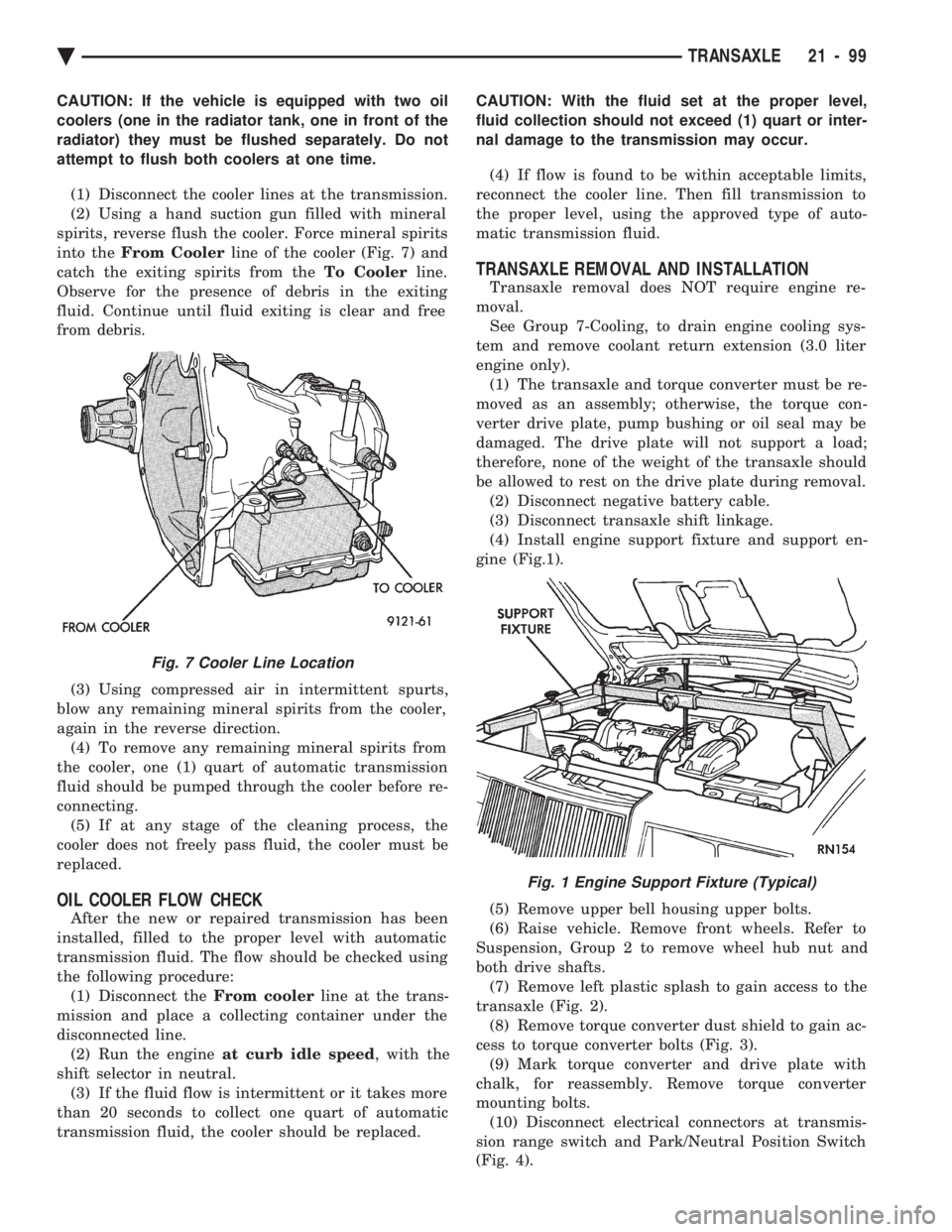
into the From Cooler line of the cooler (Fig. 7) and
catch the exiting spirits from the To Coolerline.
Observe for the presence of debris in the exiting
fluid. Continue until fluid exiting is clear and free
from debris.
(3) Using compressed air in intermittent spurts,
blow any remaining mineral spirits from the cooler,
again in the reverse direction. (4) To remove any remaining mineral spirits from
the cooler, one (1) quart of automatic transmission
fluid should be pumped through the cooler before re-
connecting. (5) If at any stage of the cleaning process, the
cooler does not freely pass fluid, the cooler must be
replaced.
OIL COOLER FLOW CHECK
After the new or repaired transmission has been
installed, filled to the proper level with automatic
transmission fluid. The flow should be checked using
the following procedure: (1) Disconnect the From coolerline at the trans-
mission and place a collecting container under the
disconnected line. (2) Run the engine at curb idle speed , with the
shift selector in neutral. (3) If the fluid flow is intermittent or it takes more
than 20 seconds to collect one quart of automatic
transmission fluid, the cooler should be replaced. CAUTION: With the fluid set at the proper level,
fluid collection should not exceed (1) quart or inter-
nal damage to the transmission may occur.
(4) If flow is found to be within acceptable limits,
reconnect the cooler line. Then fill transmission to
the proper level, using the approved type of auto-
matic transmission fluid.
TRANSAXLE REMOVAL AND INSTALLATION
Transaxle removal does NOT require engine re-
moval. See Group 7-Cooling, to drain engine cooling sys-
tem and remove coolant return extension (3.0 liter
engine only). (1) The transaxle and torque converter must be re-
moved as an assembly; otherwise, the torque con-
verter drive plate, pump bushing or oil seal may be
damaged. The drive plate will not support a load;
therefore, none of the weight of the transaxle should
be allowed to rest on the drive plate during removal. (2) Disconnect negative battery cable.
(3) Disconnect transaxle shift linkage.
(4) Install engine support fixture and support en-
gine (Fig.1).
(5) Remove upper bell housing upper bolts.
(6) Raise vehicle. Remove front wheels. Refer to
Suspension, Group 2 to remove wheel hub nut and
both drive shafts. (7) Remove left plastic splash to gain access to the
transaxle (Fig. 2). (8) Remove torque converter dust shield to gain ac-
cess to torque converter bolts (Fig. 3). (9) Mark torque converter and drive plate with
chalk, for reassembly. Remove torque converter
mounting bolts. (10) Disconnect electrical connectors at transmis-
sion range switch and Park/Neutral Position Switch
(Fig. 4).
Fig. 7 Cooler Line Location
Fig. 1 Engine Support Fixture (Typical)
Ä TRANSAXLE 21 - 99
Page 2062 of 2438
TRANSMISSION RANGE SWITCH
The transmission range switch is the white switch
located on the front of the transaxle, just above the
transaxle oil pan. CAUTION: Switch seal washer must be seated prop-
erly before tightening switch. Failure to do so may
result in leakage of transmission fluid (Fig. 6).
PARK/NEUTRAL POSITION SWITCH
The Park/Neutral Position Switch is the black
switch located to the right of the transmission range
switch.
CAUTION: Switch seal washer must be seated prop-
erly before tightening switch. Failure to do so may
result in leakage of transmission fluid (Fig. 7).
SPEED SENSOR-INPUT
CAUTION: When disconnecting speed sensor con-
nector, be sure that the weather seal does not fall
off or remain in old sensor.
The input speed sensor is located to the right of the
manual shift lever.
Fig. 2 Input Speed Sensor Removed
Fig. 3 Sound Cover
Fig. 4 Attaching Screws
Fig. 5 Solenoid Assembly
Fig. 6 Transmission Range Switch
21 - 102 TRANSAXLE Ä
Page 2065 of 2438

If screen (c) appears, the transmission control mod-
ule has completed its break-in status program. Press
the enter key on the DRB II scan tool key pad to return
the status to the start of break-in. (9) After pressing the enter key a second time in step
8 a screen will appear that says ``RESET LU CLUTCH
ARE YOU SURE ?''. Press the enter key on the DRB II
scan tool key pad. The DRB II scan tool will then carry
out the reset command. (10) After the DRB II scan tool completes the reset
command, a screen will appear saying ``LU Clutch
Break-in Status has been RESET to Start''. This screen
will indicate that the reset procedure has been success-
fully completed. (11) Disconnect the DRB II scan tool from the blue
CCD Bus connector.
TRANSAXLE RECONDITION
Tag all clutch pack assemblies, as they are
removed, for reassembly identification.
CAUTION: Do not intermix clutch discs or plates as
the unit might then fail.
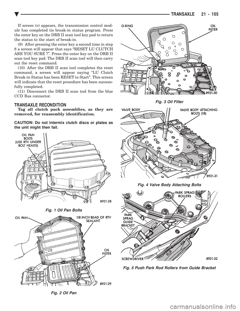
Fig. 1 Oil Pan Bolts
Fig. 2 Oil Pan
Fig. 3 Oil Filter
Fig. 4 Valve Body Attaching Bolts
Fig. 5 Push Park Rod Rollers from Guide Bracket
Ä TRANSAXLE 21 - 105
Page 2068 of 2438
CAUTION: Be sure input speed sensor is removed
before removing oil pump.
CAUTION:The cooler bypass valve must be re-
placed if a transaxle failure has occurred. Do not re- use old valve or attempt to clean old valve. When
installing bypass valve, insert with O-ring end to-
wards rear of case.
Fig. 17 Remove Oil Pump
Fig. 18 Oil Pump Removed
Fig. 19 Oil Pump Gasket
Fig. 20 Remove Bypass Valve
Fig. 21 No.1 Caged Needle Bearing
Fig. 22 Input Clutches Assembly
21 - 108 TRANSAXLE Ä
Page 2080 of 2438

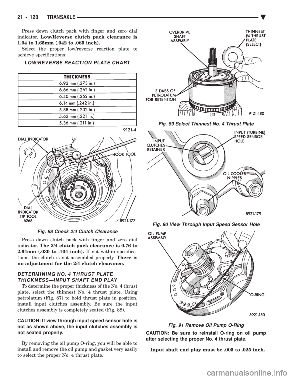
Press down clutch pack with finger and zero dial
indicator. Low/Reverse clutch pack clearance is
1.04 to 1.65mm (.042 to .065 inch). Select the proper low/reverse reaction plate to
achieve specifications:
Press down clutch pack with finger and zero dial
indicator. The 2/4 clutch pack clearance is 0.76 to
2.64mm (.030 to .104 inch). If not within specifica-
tions, the clutch is not assembled properly. There is
no adjustment for the 2/4 clutch clearance.
DETERMINING NO. 4 THRUST PLATE THICKNESSÐINPUT SHAFT END PLAY
To determine the proper thickness of the No. 4 thrust
plate, select the thinnest No. 4 thrust plate. Using
petrolatum (Fig. 87) to hold thrust plate in position,
install input clutches assembly. Be sure the input
clutches assembly is completely seated (Fig. 88).
CAUTION: If view through input speed sensor hole is
not as shown above, the input clutches assembly is
not seated properly.
By removing the oil pump O-ring, you will be able to
install and remove the oil pump and gasket very easily
to select the proper No. 4 thrust plate. CAUTION: Be sure to reinstall O-ring on oil pump
after selecting the proper No. 4 thrust plate.
Input shaft end play must be .005 to .025 inch.
LOW/REVERSE REACTION PLATE CHART
Fig. 88 Check 2/4 Clutch Clearance
Fig. 89 Select Thinnest No. 4 Thrust Plate
Fig. 90 View Through Input Speed Sensor Hole
Fig. 91 Remove Oil Pump O-Ring
21 - 120 TRANSAXLE Ä
Page 2092 of 2438

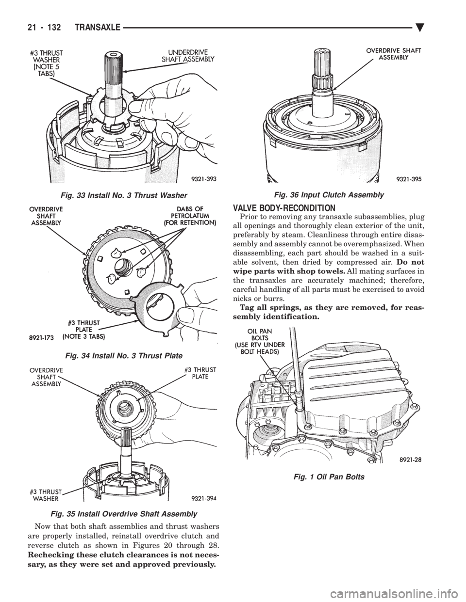
Now that both shaft assemblies and thrust washers
are properly installed, reinstall overdrive clutch and
reverse clutch as shown in Figures 20 through 28.
Rechecking these clutch clearances is not neces-
sary, as they were set and approved previously.
VALVE BODY-RECONDITION
Prior to removing any transaxle subassemblies, plug
all openings and thoroughly clean exterior of the unit,
preferably by steam. Cleanliness through entire disas-
sembly and assembly cannot be overemphasized. When
disassembling, each part should be washed in a suit-
able solvent, then dried by compressed air. Do not
wipe parts with shop towels. All mating surfaces in
the transaxles are accurately machined; therefore,
careful handling of all parts must be exercised to avoid
nicks or burrs. Tag all springs, as they are removed, for reas-
sembly identification.
Fig. 33 Install No. 3 Thrust Washer
Fig. 34 Install No. 3 Thrust Plate
Fig. 35 Install Overdrive Shaft Assembly
Fig. 36 Input Clutch Assembly
Fig. 1 Oil Pan Bolts
21 - 132 TRANSAXLE Ä
Page 2093 of 2438
Fig. 2 Oil Pan
Fig. 3 Oil Filter
Fig. 4 Valve Body Attaching Bolts
Fig. 5 Push Park Rod Rollers from Guide Bracket
Fig. 6 Remove or Install Valve Body
Fig. 7 Valve Body Removed
Ä TRANSAXLE 21 - 133
Page 2096 of 2438
When installing valve body assembly onto tran-
saxle, observe Figure 5. Guide park rod rollers into
guide bracket, while shifting manual lever assembly
out of the installation position.
OIL PUMP SEAL REPLACE DIFFERENTIAL REPAIR
The transfer shaft should be removed for differen-
tial repair and bearing turning torque checking.
Fig. 16 Remove Oil Pump Seal
Fig. 17 Install Oil Pump Seal
Fig. 1 Remove Extension Seal
Fig. 2 Install New Seal Into Extension
Fig. 14 Remove or Install Dual Retainer Plate
Fig. 15 Remove or Install Retainer Plate
21 - 136 TRANSAXLE Ä