Page 1965 of 2438

TRANSAXLE REMOVAL AND INSTALLATION
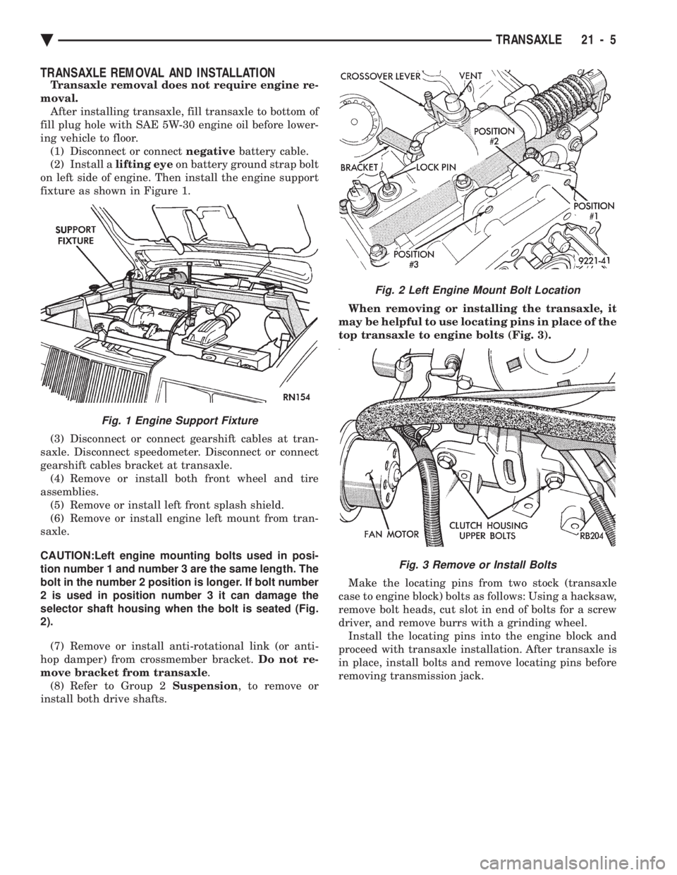
Transaxle removal does not require engine re-
moval. After installing transaxle, fill transaxle to bottom of
fill plug hole with SAE 5W-30 engine oil before lower-
ing vehicle to floor. (1) Disconnect or connect negativebattery cable.
(2) Install a lifting eyeon battery ground strap bolt
on left side of engine. Then install the engine support
fixture as shown in Figure 1.
(3) Disconnect or connect gearshift cables at tran-
saxle. Disconnect speedometer. Disconnect or connect
gearshift cables bracket at transaxle. (4) Remove or install both front wheel and tire
assemblies. (5) Remove or install left front splash shield.
(6) Remove or install engine left mount from tran-
saxle.
CAUTION:Left engine mounting bolts used in posi-
tion number 1 and number 3 are the same length. The
bolt in the number 2 position is longer. If bolt number
2 is used in position number 3 it can damage the
selector shaft housing when the bolt is seated (Fig.
2).
(7) Remove or install anti-rotational link (or anti-
hop damper) from crossmember bracket. Do not re-
move bracket from transaxle .
(8) Refer to Group 2 Suspension, to remove or
install both drive shafts. When removing or installing the transaxle, it
may be helpful to use locating pins in place of the
top transaxle to engine bolts (Fig. 3).
Make the locating pins from two stock (transaxle
case to engine block) bolts as follows: Using a hacksaw,
remove bolt heads, cut slot in end of bolts for a screw
driver, and remove burrs with a grinding wheel. Install the locating pins into the engine block and
proceed with transaxle installation. After transaxle is
in place, install bolts and remove locating pins before
removing transmission jack.
Fig. 1 Engine Support Fixture
Fig. 2 Left Engine Mount Bolt Location
Fig. 3 Remove or Install Bolts
Ä TRANSAXLE 21 - 5
Page 1974 of 2438
CLUTCH RELEASE BEARING INPUT SHAFT OIL SEAL
Fig. 34 Remove or Install Gear Set
Fig. 35 Gear Set
Fig. 1 Remove Retaining E-Clip
Fig. 2 Remove or Install Clutch Release Shaft
Fig. 3 Clutch Release Shaft Components
Fig. 4 Remove or Install Input Shaft Seal Retainer
21 - 14 TRANSAXLE
Ä
Page 1976 of 2438
Use Tool C-4660-2A Screw. The screw has a larger
hole in the lower end to fit over the larger oil feeder
nipple (Fig. 5).
INTERMEDIATE SHAFT ASSEMBLY
Intermediate shaft ball bearing seal color:
A-525/A-523/A-543 Black, A-568 Blue.
Fig. 3 Remove or Install Bearing Retaining Strap
Fig. 4 Remove Intermediate Shaft Front Bearing
Fig. 5 Oil Feeder
Fig. 6 Install Intermediate Shaft Front Bearing
Fig. 1 Intermediate Shaft Bearing Snap Ring
Fig. 2 Remove Intermediate Shaft Rear Bearing
21 - 16 TRANSAXLE Ä
Page 1982 of 2438
The C-Clip groves in the selector shaft will
damage the oil seal. Install oil seal after selector
shaft is installed. Always use a new oil seal when
selector shaft is removed. Proper torque to the 5-R blocker attaching
bolts is very important (Fig. 8).
Fig. 4 Remove Oil Seal
Fig. 5 Install Oil Seal
Fig. 6 Remove Vent Cap
Fig. 7 Crossover Shaft Roll Pin
Fig. 8 5-R Blocker Attaching Bolts
Fig. 9 5-R Blocker Assembly
21 - 22 TRANSAXLE Ä
Page 1984 of 2438
DIFFERENTIAL BEARING RETAINER
Fig. 1 Remove Differential Bearing Retainer Seal
Fig. 2 Install Differential Bearing Retainer Seal
Fig. 3 Remove Differential Bearing Retainer Cup
Fig. 4 Differential Bearing Retainer
Fig. 5 Install Oil Baffle
Fig. 6 Insert (Select) Shim and Differential Bearing Retainer Cup
21 - 24 TRANSAXLE Ä
Page 1985 of 2438
EXTENSION HOUSING
Fig. 1 Remove Extension Seal
Fig. 2 Install New Seal into Extension
Fig. 3 Remove Extension Bearing Cup
Fig. 4 Extension
Fig. 5 Install Extension Oil Baffle
Fig. 6 Install Extension Bearing Cup
Ä TRANSAXLE 21 - 25
Page 1992 of 2438

ing seat will give a false end play reading while
gauging for proper shims. Improperly seated bearing
cups and cones are subject to low mileage failure.(2) Bearing cups and cones should be replaced if they
show signs of pitting or heat distress. If distress is seen
on either the cup or bearing rollers, both cup and cone
must be replaced. (3) Bearing preload and drag torque specifications
must be maintained to avoid premature bearing
failures. Used (original) bearing may lose up to 50% of
the original drag torque after break in. All bearing
adjustments must be made with no other compo-
nent interference or gear intermesh. (4) Replace bearings as a pair. For example, if one
differential bearing is defective, replace both differen-
tial bearings. If one input shaft bearing is defective,
replace both input shaft bearings. (5) Bearing cones must notbe reused if removed.
(6) Turning torque readings should be obtained
while smoothly rotating in either direction (break-
away reading is not indicative of the true turning
torque). (7) Replace oil baffle, if damaged.
INPUT SHAFT BEARING END PLAY ADJUST-MENT
(1) Using Tool C-4656 with Handle C-4171, press
input shaft front bearing cup slightly forward in case.
Then, using Tool C-4655 with Handle C-4171, press
bearing cup back into case from the front. Properly
position bearing cup, before checking input shaft end
play (see input shaft front bearing cup replace in
Subassembly Recondition section).This step is
not necessary if Tool C-4655 was previously used
to install input shaft front bearing cup in the
case. Also no input shaft shim has been installed
since pressing cup into case. (2) Select a gauging shim which will give 0.025 to
0.254mm (.001 to .010 inch) end play. SUGGESTION:
Measure original shim from input shaft seal retainer and select a shim 0.254mm (.010
inch) thinner than original for the gauging shim.
(3) Install gauging shim on bearing cup and install
input shaft seal retainer.
CAUTION: The input shaft seal retainer is used to
draw the input shaft front bearing cup the proper
distance into the case bore during this step. Alter-
nately tighten input shaft seal retainer bolts until
input shaft seal retainer is bottomed against case.
Tighten bolts to 28 N Im (21 ft. lbs.).
(4) Oil input shaft bearings with SAE 5W-30 engine
oil and install input shaft in case. Install bearing
retainer plate with input shaft rear bearing cup
pressed in and bearing support plate installed. Tighten
all bolts and nuts to 28 N Im (21 ft. lbs.).
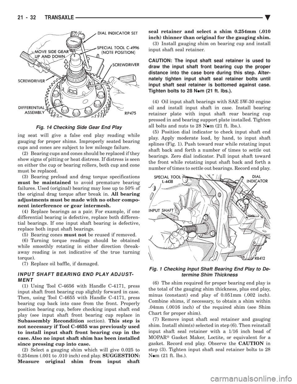
(5) Position dial indicator to check input shaft end
play. Apply moderate load, by hand, to input shaft
splines (Fig. 1). Push toward rear while rotating input
shaft back and forth a number of times to settle out
bearings. Zero dial indicator. Pull input shaft toward
the front while rotating input shaft back and forth a
number of times to settle out bearings. Record end play.
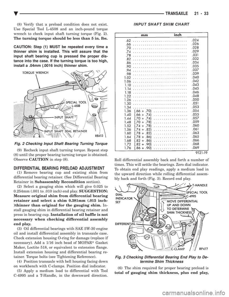
(6) The shim required for proper bearing end play is
the total of the gauging shim thickness, plus end play,
minus (constant) end play of 0.051mm (.002 inch).
Combine shims, if necessary, to obtain a shim within
.04mm (.0016 inch) of the required shim (see Shim
Chart for proper shim). (7) Remove input shaft seal retainer and gauging
shim. Install shim(s) selected in step (6). Then reinstall
input shaft seal retainer with a 1/16 inch bead of
MOPAR tGasket Maker, Loctite, or equivalent for a
gasket. Record end play. Observe the CAUTIONin
step (3). Tighten input shaft seal retainer bolts to 28
N Im (21 ft. lbs.).
Fig. 14 Checking Side Gear End Play
Fig. 1 Checking Input Shaft Bearing End Play to De-
termine Shim Thickness
21 - 32 TRANSAXLE Ä
Page 1993 of 2438

(8) Verify that a preload condition does not exist.
Use Special Tool L-4508 and an inch-pound torque
wrench to check input shaft turning torque (Fig. 2).
The turning torque should be less than 5 in. lbs.
CAUTION: Step (1) MUST be repeated every time a
thinner shim is installed. This will assure that the
input shaft bearing cup is pressed the proper dis-
tance into the case. If the turning torque is too high,
install a .04mm (.0016 inch) thinner shim.
(9) Recheck input shaft turning torque. Repeat step
(8) until the proper bearing turning torque is obtained.
Observe CAUTION in step (8).
DIFFERENTIAL BEARING PRELOAD ADJUSTMENT
(1) Remove bearing cup and existing shim from
differential bearing retainer. (See Differential Bearing
Retainer in Subassembly Recondition section).
(2) Select a gauging shim which will give 0.025 to
0.254mm (.001 to .010 inch) end play. SUGGESTION:
Measure original shim from differential bearing
retainer and select a shim 0.381mm (.015 inch-
)thinner than original for the gauging shim. In-
stall gauging shim in differential bearing retainer and
press in bearing cup. Installation of oil baffle is not
necessary when checking differential assembly
end play. (3) Oil differential bearings with SAE 5W-30 engine
oil and install differential assembly in transaxle case.
Check extension housing O-ring for damage (replace if
necessary). Add a 1/16 inch bead of MOPAR tGasket
Maker, Loctite 518, or equivalent to extension flange.
Install extension housing and differential bearing re-
tainer. Torque bolts (see Tightening Reference). (4) Position transaxle with bell housing facing down
on workbench with C-clamps. Position dial indicator. (5) Apply a medium load to differential with Tool
C-4995 and a T-Handle, in the downward direction. Roll differential assembly back and forth a number of
times. This will settle the bearings. Zero dial indicator.
To obtain end play readings, apply a medium load in
the upward direction while rolling differential assem-
bly back and forth (Fig. 3). Record end play.
(6) The shim required for proper bearing preload is
total of gauging shim thickness, plus end play,
Fig. 2 Checking Input Shaft Bearing Turning Torque
INPUT SHAFT SHIM CHART
Fig. 3 Checking Differential Bearing End Play to De- termine Shim Thickness
Ä TRANSAXLE 21 - 33