1993 CHEVROLET DYNASTY oil
[x] Cancel search: oilPage 1930 of 2438
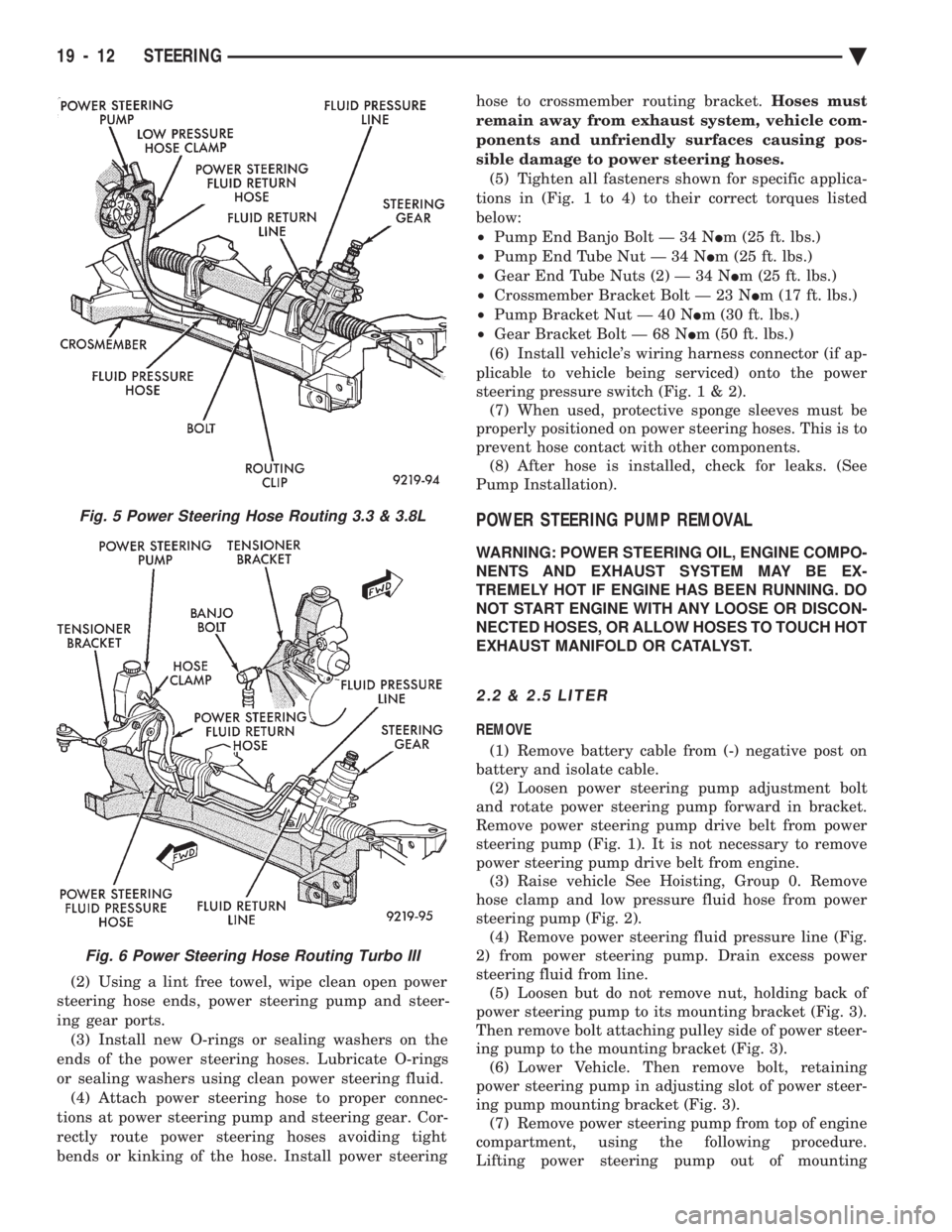
(2) Using a lint free towel, wipe clean open power
steering hose ends, power steering pump and steer-
ing gear ports. (3) Install new O-rings or sealing washers on the
ends of the power steering hoses. Lubricate O-rings
or sealing washers using clean power steering fluid. (4) Attach power steering hose to proper connec-
tions at power steering pump and steering gear. Cor-
rectly route power steering hoses avoiding tight
bends or kinking of the hose. Install power steering hose to crossmember routing bracket.
Hoses must
remain away from exhaust system, vehicle com-
ponents and unfriendly surfaces causing pos-
sible damage to power steering hoses. (5) Tighten all fasteners shown for specific applica-
tions in (Fig. 1 to 4) to their correct torques listed
below:
² Pump End Banjo Bolt Ð 34 N Im (25 ft. lbs.)
² Pump End Tube Nut Ð 34 N Im (25 ft. lbs.)
² Gear End Tube Nuts (2) Ð 34 N Im (25 ft. lbs.)
² Crossmember Bracket Bolt Ð 23 N Im (17 ft. lbs.)
² Pump Bracket Nut Ð 40 N Im (30 ft. lbs.)
² Gear Bracket Bolt Ð 68 N Im (50 ft. lbs.)
(6) Install vehicle's wiring harness connector (if ap-
plicable to vehicle being serviced) onto the power
steering pressure switch (Fig .1&2).
(7) When used, protective sponge sleeves must be
properly positioned on power steering hoses. This is to
prevent hose contact with other components. (8) After hose is installed, check for leaks. (See
Pump Installation).
POWER STEERING PUMP REMOVAL
WARNING: POWER STEERING OIL, ENGINE COMPO-
NENTS AND EXHAUST SYSTEM MAY BE EX-
TREMELY HOT IF ENGINE HAS BEEN RUNNING. DO
NOT START ENGINE WITH ANY LOOSE OR DISCON-
NECTED HOSES, OR ALLOW HOSES TO TOUCH HOT
EXHAUST MANIFOLD OR CATALYST.
2.2 & 2.5 LITER
REMOVE
(1) Remove battery cable from (-) negative post on
battery and isolate cable. (2) Loosen power steering pump adjustment bolt
and rotate power steering pump forward in bracket.
Remove power steering pump drive belt from power
steering pump (Fig. 1). It is not necessary to remove
power steering pump drive belt from engine. (3) Raise vehicle See Hoisting, Group 0. Remove
hose clamp and low pressure fluid hose from power
steering pump (Fig. 2). (4) Remove power steering fluid pressure line (Fig.
2) from power steering pump. Drain excess power
steering fluid from line. (5) Loosen but do not remove nut, holding back of
power steering pump to its mounting bracket (Fig. 3).
Then remove bolt attaching pulley side of power steer-
ing pump to the mounting bracket (Fig. 3). (6) Lower Vehicle. Then remove bolt, retaining
power steering pump in adjusting slot of power steer-
ing pump mounting bracket (Fig. 3). (7) Remove power steering pump from top of engine
compartment, using the following procedure.
Lifting power steering pump out of mounting
Fig. 5 Power Steering Hose Routing 3.3 & 3.8L
Fig. 6 Power Steering Hose Routing Turbo III
19 - 12 STEERING Ä
Page 1932 of 2438
(10) Connect negative cable back on negative post
of battery. (11) Start engine and turn steering wheel several
times from stop to stop to bleed air from fluid in sys-
tem. Stop engine, check fluid level, and inspect sys-
tem for leaks. See Checking Fluid Level.
3.0 LITER
REMOVE
(1) REMOVE THE (-) NEGATIVE BATTERY CA-
BLE FROM THE BATTERY AND ISOLATE CA-
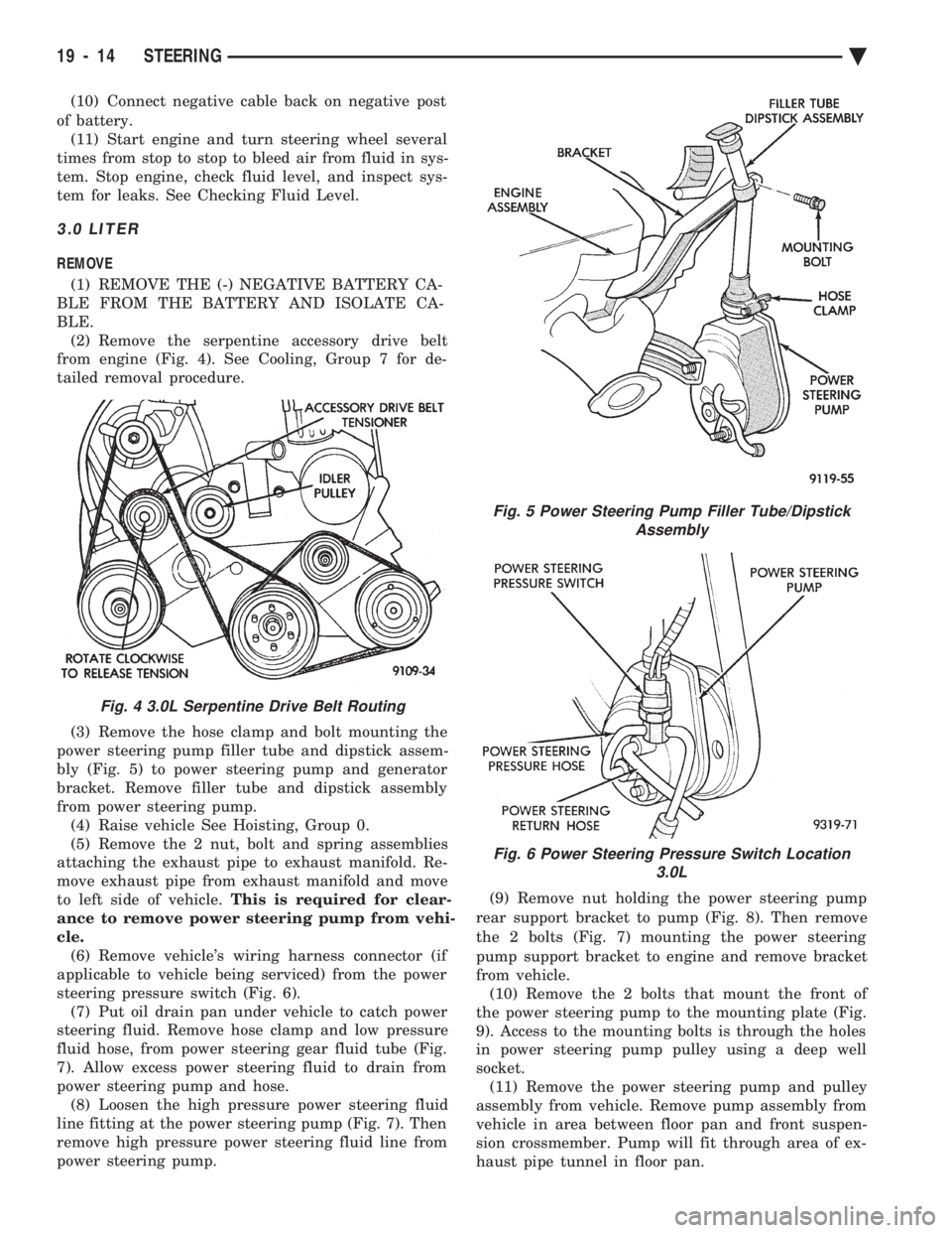
BLE. (2) Remove the serpentine accessory drive belt
from engine (Fig. 4). See Cooling, Group 7 for de-
tailed removal procedure.
(3) Remove the hose clamp and bolt mounting the
power steering pump filler tube and dipstick assem-
bly (Fig. 5) to power steering pump and generator
bracket. Remove filler tube and dipstick assembly
from power steering pump. (4) Raise vehicle See Hoisting, Group 0.
(5) Remove the 2 nut, bolt and spring assemblies
attaching the exhaust pipe to exhaust manifold. Re-
move exhaust pipe from exhaust manifold and move
to left side of vehicle. This is required for clear-
ance to remove power steering pump from vehi-
cle. (6) Remove vehicle's wiring harness connector (if
applicable to vehicle being serviced) from the power
steering pressure switch (Fig. 6). (7) Put oil drain pan under vehicle to catch power
steering fluid. Remove hose clamp and low pressure
fluid hose, from power steering gear fluid tube (Fig.
7). Allow excess power steering fluid to drain from
power steering pump and hose. (8) Loosen the high pressure power steering fluid
line fitting at the power steering pump (Fig. 7). Then
remove high pressure power steering fluid line from
power steering pump. (9) Remove nut holding the power steering pump
rear support bracket to pump (Fig. 8). Then remove
the 2 bolts (Fig. 7) mounting the power steering
pump support bracket to engine and remove bracket
from vehicle. (10) Remove the 2 bolts that mount the front of
the power steering pump to the mounting plate (Fig.
9). Access to the mounting bolts is through the holes
in power steering pump pulley using a deep well
socket. (11) Remove the power steering pump and pulley
assembly from vehicle. Remove pump assembly from
vehicle in area between floor pan and front suspen-
sion crossmember. Pump will fit through area of ex-
haust pipe tunnel in floor pan.
Fig. 4 3.0L Serpentine Drive Belt Routing
Fig. 5 Power Steering Pump Filler Tube/Dipstick Assembly
Fig. 6 Power Steering Pressure Switch Location 3.0L
19 - 14 STEERING Ä
Page 1934 of 2438
(15) Start engine and turn steering wheel several
times from stop to stop to bleed air from fluid in sys-
tem. Stop engine, check fluid level, and inspect sys-
tem for leaks. See Checking Fluid Level.
3.3 & 3.8 LITER
REMOVE
(1) Remove the (-) negative battery cable from the
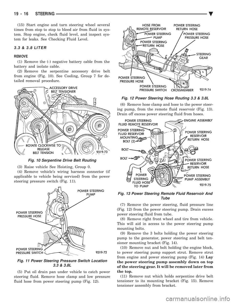
battery and isolate cable. (2) Remove the serpentine accessory drive belt
from engine (Fig. 10). See Cooling, Group 7 for de-
tailed removal procedure.
(3) Raise vehicle See Hoisting, Group 0.
(4) Remove vehicle's wiring harness connector (if
applicable to vehicle being serviced) from the power
steering pressure switch (Fig. 11).
(5) Put oil drain pan under vehicle to catch power
steering fluid. Remove hose clamp and low pressure
fluid hose from power steering pump (Fig. 12). (6) Remove hose clamp and hose to the power steer-
ing pump, from the remote fluid reservoir (Fig. 13).
Drain off excess power steering fluid from hoses.
(7) Remove the power steering, fluid pressure line
(Fig. 12) from the power steering pump. Drain excess
power steering fluid from tube. (8) Remove right front wheel and tire from vehicle.
This will aid in access to the power steering pump
mounting bolts. (9) Remove the 3 bolts holding the power steering
pump to the generator, power steering and belt ten-
sioner mounting bracket (Fig. 14). (10) Remove nut and bolt holding the engine block,
to power steering pump support strut. Remove strut
from engine and power steering pump (Fig. 14) Lay
the power steering pump assembly down on top
of the steering gear. It will be removed later from
the top. (11) Remove nut which holds serpentine drive belt
tensioner to its mounting bracket (Fig. 15). Remove
tensioner assembly from bracket.
Fig. 10 Serpentine Drive Belt Routing
Fig. 11 Power Steering Pressure Switch Location 3.3 & 3.8L
Fig. 12 Power Steering Hose Routing 3.3 & 3.8L
Fig. 13 Power Steering Remote Fluid Reservoir And Tube
19 - 16 STEERING Ä
Page 1937 of 2438
(18) Lower vehicle.
(19) Install the serpentine drive belt. Refer to (Fig.
10) for correct serpentine belt routing. See Cooling,
Group 7 for detailed installation procedure.
CAUTION: Do not use automatic transmission fluid
in power steering system. Only use Mopar T, Power
Steering Fluid, or equivalent.
(20) Fill power steering pump reservoir to correct
fluid level. (21) Connect the negative battery cable on the
negative battery post. (22) Start engine and turn steering wheel several
times from stop to stop to bleed air from fluid in sys-
tem. Stop engine, check fluid level, and inspect sys-
tem for leaks. See Checking Fluid Level.
TURBO III
REMOVE
(1) Disconnect the battery (-) negative cable from
the battery and isolate cable. (2) Raise vehicle See Hoisting, Group 0. Put oil
drain pan under vehicle to catch power steering
fluid. (3) Remove the right front underhood splash shield
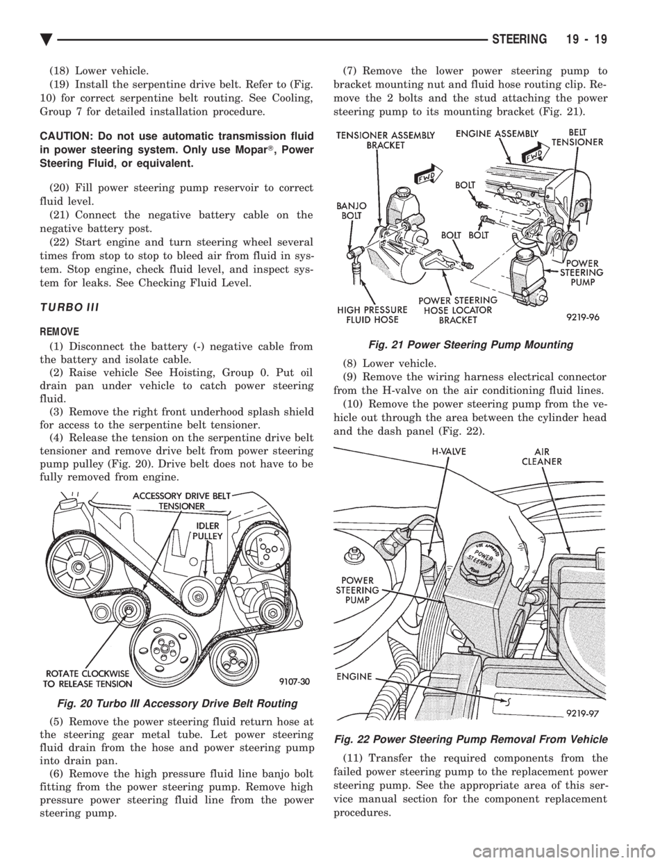
for access to the serpentine belt tensioner. (4) Release the tension on the serpentine drive belt
tensioner and remove drive belt from power steering
pump pulley (Fig. 20). Drive belt does not have to be
fully removed from engine.
(5) Remove the power steering fluid return hose at
the steering gear metal tube. Let power steering
fluid drain from the hose and power steering pump
into drain pan. (6) Remove the high pressure fluid line banjo bolt
fitting from the power steering pump. Remove high
pressure power steering fluid line from the power
steering pump. (7) Remove the lower power steering pump to
bracket mounting nut and fluid hose routing clip. Re-
move the 2 bolts and the stud attaching the power
steering pump to its mounting bracket (Fig. 21).
(8) Lower vehicle.
(9) Remove the wiring harness electrical connector
from the H-valve on the air conditioning fluid lines. (10) Remove the power steering pump from the ve-
hicle out through the area between the cylinder head
and the dash panel (Fig. 22).
(11) Transfer the required components from the
failed power steering pump to the replacement power
steering pump. See the appropriate area of this ser-
vice manual section for the component replacement
procedures.
Fig. 20 Turbo III Accessory Drive Belt Routing
Fig. 21 Power Steering Pump Mounting
Fig. 22 Power Steering Pump Removal From Vehicle
Ä STEERING 19 - 19
Page 1943 of 2438
POWER STEERING GEAR INDEX
page page
General Information ....................... 25
Outer Tie Rod ........................... 27 Steering Gear Service
..................... 25
GENERAL INFORMATION
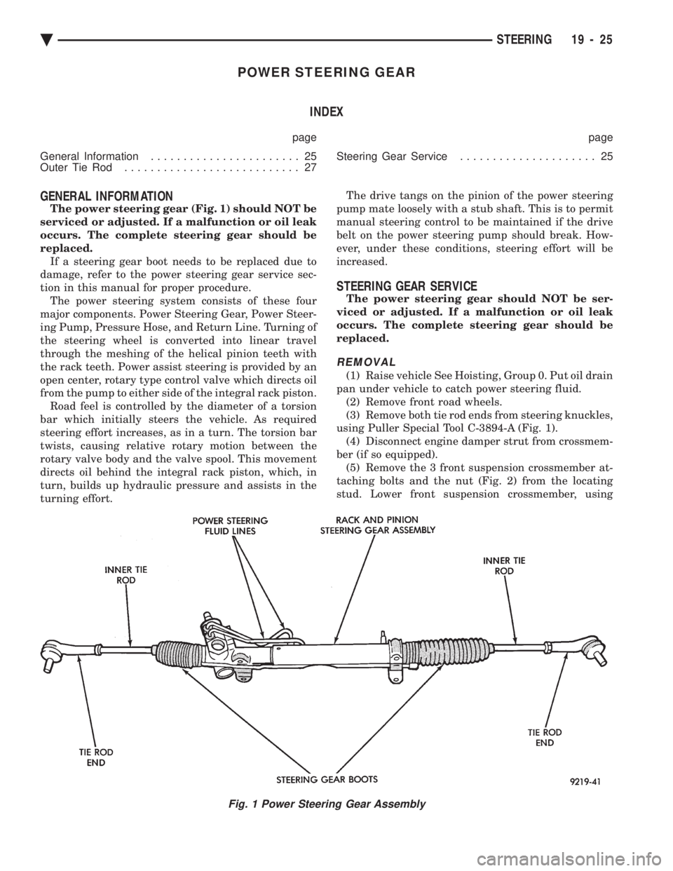
The power steering gear (Fig. 1) should NOT be
serviced or adjusted. If a malfunction or oil leak
occurs. The complete steering gear should be
replaced. If a steering gear boot needs to be replaced due to
damage, refer to the power steering gear service sec-
tion in this manual for proper procedure. The power steering system consists of these four
major components. Power Steering Gear, Power Steer-
ing Pump, Pressure Hose, and Return Line. Turning of
the steering wheel is converted into linear travel
through the meshing of the helical pinion teeth with
the rack teeth. Power assist steering is provided by an
open center, rotary type control valve which directs oil
from the pump to either side of the integral rack piston. Road feel is controlled by the diameter of a torsion
bar which initially steers the vehicle. As required
steering effort increases, as in a turn. The torsion bar
twists, causing relative rotary motion between the
rotary valve body and the valve spool. This movement
directs oil behind the integral rack piston, which, in
turn, builds up hydraulic pressure and assists in the
turning effort. The drive tangs on the pinion of the power steering
pump mate loosely with a stub shaft. This is to permit
manual steering control to be maintained if the drive
belt on the power steering pump should break. How-
ever, under these conditions, steering effort will be
increased.
STEERING GEAR SERVICE
The power steering gear should NOT be ser-
viced or adjusted. If a malfunction or oil leak
occurs. The complete steering gear should be
replaced.
REMOVAL
(1) Raise vehicle See Hoisting, Group 0. Put oil drain
pan under vehicle to catch power steering fluid. (2) Remove front road wheels.
(3) Remove both tie rod ends from steering knuckles,
using Puller Special Tool C-3894-A (Fig. 1). (4) Disconnect engine damper strut from crossmem-
ber (if so equipped). (5) Remove the 3 front suspension crossmember at-
taching bolts and the nut (Fig. 2) from the locating
stud. Lower front suspension crossmember, using
Fig. 1 Power Steering Gear Assembly
Ä STEERING 19 - 25
Page 1961 of 2438
TRANSAXLE
CONTENTS
page page
41TE FOUR SPEED AUTOMATIC TRANSAXLE . 85
41TE FOUR SPEED TRANSAXLE HYDRAULICSCHEMATICS ........................ 170
41TE ON-BOARD DIAGNOSTICS .......... 145
A-523, A-543, and A-568 MANUAL TRANSAXLE ........................... 1 SPECIFICATIONS
...................... 183
THREE SPEED TORQUEFLITE AUTOMATIC TRANSAXLE .......................... 35
THREE SPEED TRANSAXLE HYDRAULIC SCHEMATICS ........................ 162
A-523, A-543, and A-568 MANUAL TRANSAXLE INDEX
page page
Bearing Adjustment Procedure .............. 31
Differential Bearing Preload Adjustment ........ 33
Gearshift Linkage Adjustment (Cable Operated) . . 2
General Information ........................ 1 In-Car Transaxle Disassemble/Assemble
........ 4
Out of Car TransaxleÐDisassemble and Assemble . 6
Subassembly-Recondition .................. 15
Transaxle Removal and Installation ............ 5
GENERAL INFORMATION
Safety goggles should be worn at all times
when working on these transaxles. All manual
transaxles use SAE 5W-30 engine oil, meeting SG
and/or SG-CC qualifications, as the lubricant in order
to reduce wear. This 5-speed manual transaxles combine gear reduc-
tion, ratio selection, and differential functions in one
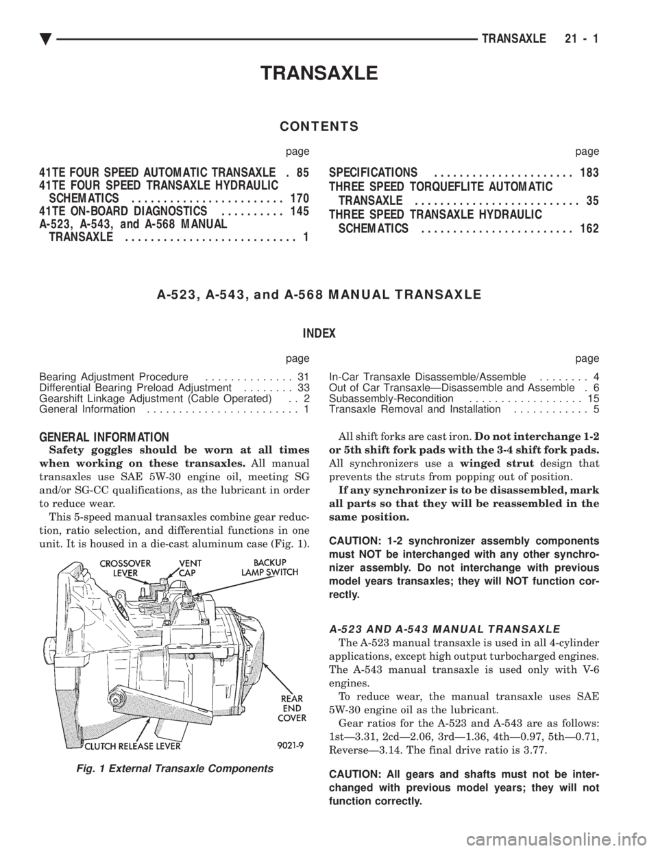
unit. It is housed in a die-cast aluminum case (Fig. 1). All shift forks are cast iron.
Do not interchange 1-2
or 5th shift fork pads with the 3-4 shift fork pads.
All synchronizers use a winged strutdesign that
prevents the struts from popping out of position. If any synchronizer is to be disassembled, mark
all parts so that they will be reassembled in the
same position.
CAUTION: 1-2 synchronizer assembly components
must NOT be interchanged with any other synchro-
nizer assembly. Do not interchange with previous
model years transaxles; they will NOT function cor-
rectly.
A-523 AND A-543 MANUAL TRANSAXLE
The A-523 manual transaxle is used in all 4-cylinder
applications, except high output turbocharged engines.
The A-543 manual transaxle is used only with V-6
engines. To reduce wear, the manual transaxle uses SAE
5W-30 engine oil as the lubricant. Gear ratios for the A-523 and A-543 are as follows:
1stÐ3.31, 2cdÐ2.06, 3rdÐ1.36, 4thÐ0.97, 5thÐ0.71,
ReverseÐ3.14. The final drive ratio is 3.77.
CAUTION: All gears and shafts must not be inter-
changed with previous model years; they will not
function correctly.
Fig. 1 External Transaxle Components
Ä TRANSAXLE 21 - 1
Page 1962 of 2438
A-568 HEAVYÐDUTY MANUAL TRANSAXLE
The greater torque of the high output turbo engines
require a stronger transmission. It includes a die-cast
aluminum case and a stronger, coarse-pitch gear set. It
has five forward speed ratios and reverse. Gear ratios
are as follows: 1stÐ3.31, 2ndÐ1.89, 3rdÐ1.28,
4thÐ0.94, 5thÐ0.71, ReverseÐ3.14. Final drive ratio
of 3.85 was selected for maximum performance. All
forward gears are synchronized. To reduce wear, this transaxle, in common with other
manual transaxles, uses SAE 5W-30 engine oil as the
lubricant.
IDENTIFICATION
A-523, A-543, and A-568: the transaxle model, assem-
bly number, build date, and final-drive ratio are
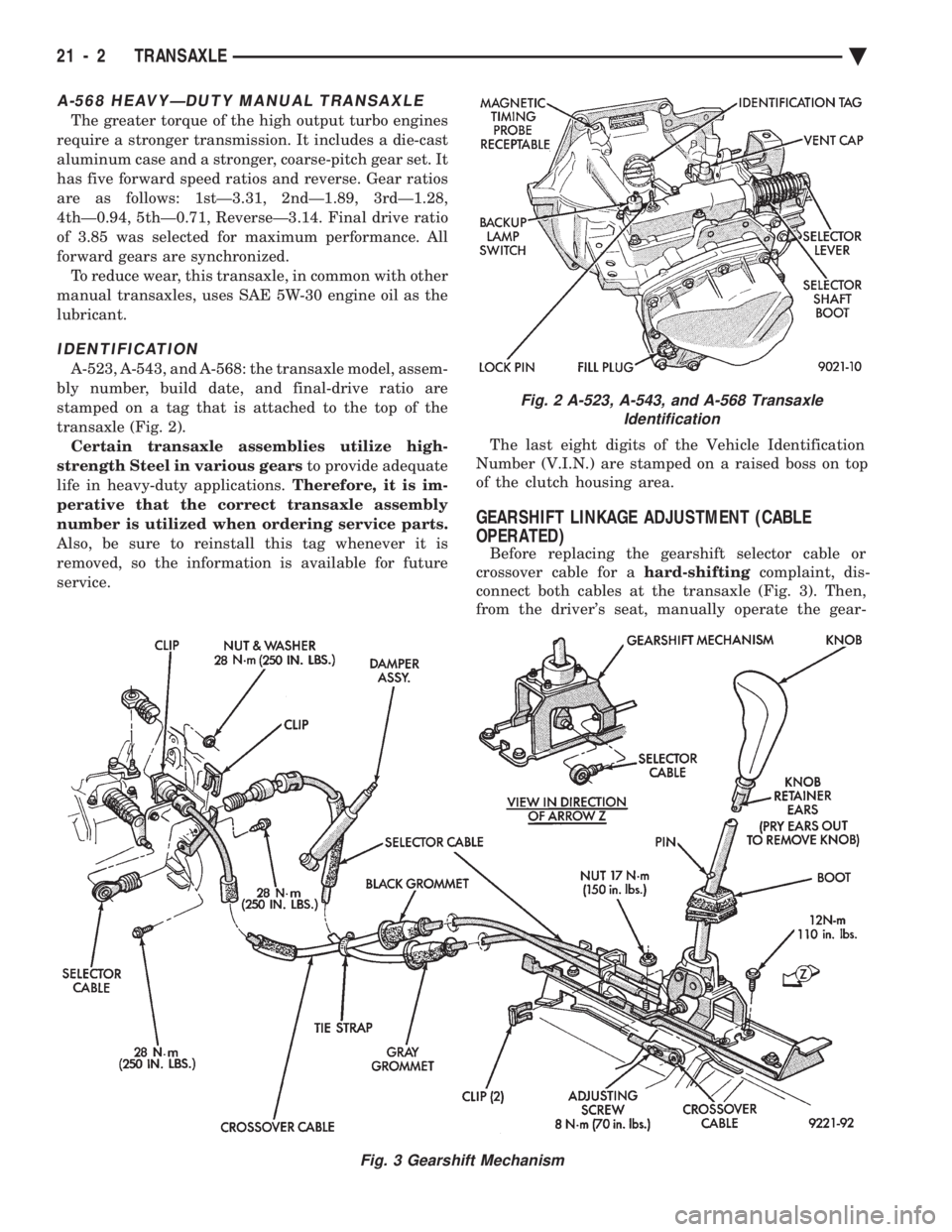
stamped on a tag that is attached to the top of the
transaxle (Fig. 2). Certain transaxle assemblies utilize high-
strength Steel in various gears to provide adequate
life in heavy-duty applications. Therefore, it is im-
perative that the correct transaxle assembly
number is utilized when ordering service parts.
Also, be sure to reinstall this tag whenever it is
removed, so the information is available for future
service. The last eight digits of the Vehicle Identification
Number (V.I.N.) are stamped on a raised boss on top
of the clutch housing area.
GEARSHIFT LINKAGE ADJUSTMENT (CABLE
OPERATED)
Before replacing the gearshift selector cable or
crossover cable for a hard-shiftingcomplaint, dis-
connect both cables at the transaxle (Fig. 3). Then,
from the driver's seat, manually operate the gear-
Fig. 2 A-523, A-543, and A-568 Transaxle Identification
Fig. 3 Gearshift Mechanism
21 - 2 TRANSAXLE Ä
Page 1964 of 2438
CAUTION: Be sure crossover bellcrank does NOT
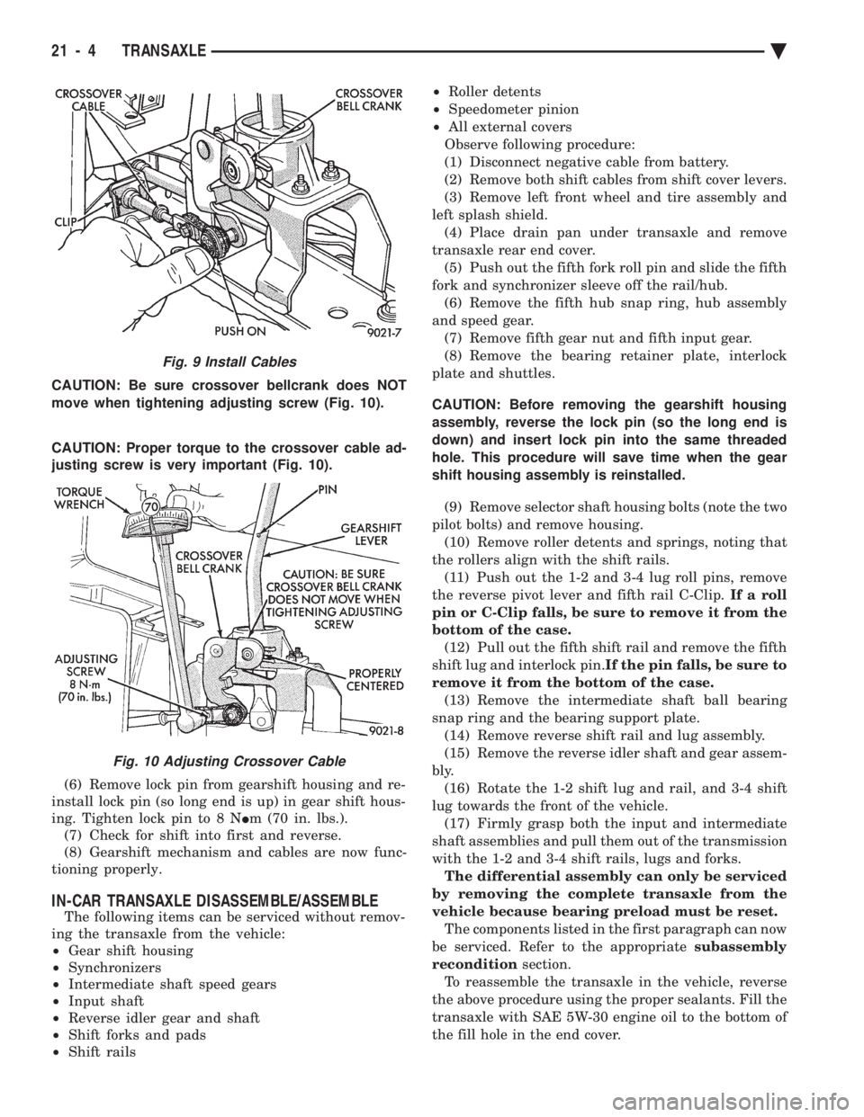
move when tightening adjusting screw (Fig. 10).
CAUTION: Proper torque to the crossover cable ad-
justing screw is very important (Fig. 10).
(6) Remove lock pin from gearshift housing and re-
install lock pin (so long end is up) in gear shift hous-
ing. Tighten lock pin to 8 N Im (70 in. lbs.).
(7) Check for shift into first and reverse.
(8) Gearshift mechanism and cables are now func-
tioning properly.
IN-CAR TRANSAXLE DISASSEMBLE/ASSEMBLE
The following items can be serviced without remov-
ing the transaxle from the vehicle:
² Gear shift housing
² Synchronizers
² Intermediate shaft speed gears
² Input shaft
² Reverse idler gear and shaft
² Shift forks and pads
² Shift rails ²
Roller detents
² Speedometer pinion
² All external covers
Observe following procedure:
(1) Disconnect negative cable from battery.
(2) Remove both shift cables from shift cover levers.
(3) Remove left front wheel and tire assembly and
left splash shield. (4) Place drain pan under transaxle and remove
transaxle rear end cover. (5) Push out the fifth fork roll pin and slide the fifth
fork and synchronizer sleeve off the rail/hub. (6) Remove the fifth hub snap ring, hub assembly
and speed gear. (7) Remove fifth gear nut and fifth input gear.
(8) Remove the bearing retainer plate, interlock
plate and shuttles.
CAUTION: Before removing the gearshift housing
assembly, reverse the lock pin (so the long end is
down) and insert lock pin into the same threaded
hole. This procedure will save time when the gear
shift housing assembly is reinstalled. (9) Remove selector shaft housing bolts (note the two
pilot bolts) and remove housing. (10) Remove roller detents and springs, noting that
the rollers align with the shift rails. (11) Push out the 1-2 and 3-4 lug roll pins, remove
the reverse pivot lever and fifth rail C-Clip. If a roll
pin or C-Clip falls, be sure to remove it from the
bottom of the case. (12) Pull out the fifth shift rail and remove the fifth
shift lug and interlock pin. If the pin falls, be sure to
remove it from the bottom of the case. (13) Remove the intermediate shaft ball bearing
snap ring and the bearing support plate. (14) Remove reverse shift rail and lug assembly.
(15) Remove the reverse idler shaft and gear assem-
bly. (16) Rotate the 1-2 shift lug and rail, and 3-4 shift
lug towards the front of the vehicle. (17) Firmly grasp both the input and intermediate
shaft assemblies and pull them out of the transmission
with the 1-2 and 3-4 shift rails, lugs and forks. The differential assembly can only be serviced
by removing the complete transaxle from the
vehicle because bearing preload must be reset. The components listed in the first paragraph can now
be serviced. Refer to the appropriate subassembly
recondition section.
To reassemble the transaxle in the vehicle, reverse
the above procedure using the proper sealants. Fill the
transaxle with SAE 5W-30 engine oil to the bottom of
the fill hole in the end cover.
Fig. 9 Install Cables
Fig. 10 Adjusting Crossover Cable
21 - 4 TRANSAXLE Ä