1993 CHEVROLET DYNASTY warning
[x] Cancel search: warningPage 2221 of 2438
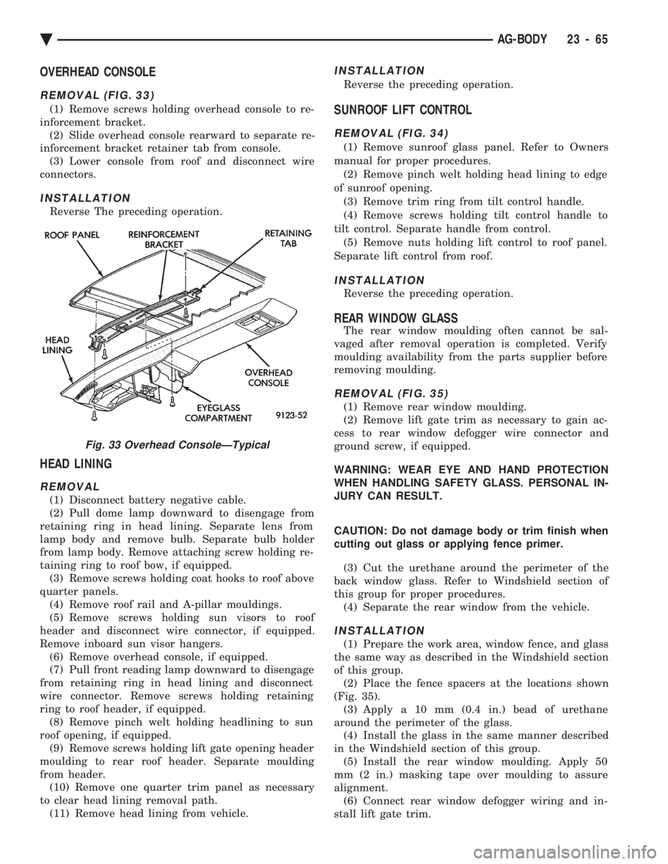
OVERHEAD CONSOLE
REMOVAL (FIG. 33)
(1) Remove screws holding overhead console to re-
inforcement bracket. (2) Slide overhead console rearward to separate re-
inforcement bracket retainer tab from console. (3) Lower console from roof and disconnect wire
connectors.
INSTALLATION
Reverse The preceding operation.
HEAD LINING
REMOVAL
(1) Disconnect battery negative cable.
(2) Pull dome lamp downward to disengage from
retaining ring in head lining. Separate lens from
lamp body and remove bulb. Separate bulb holder
from lamp body. Remove attaching screw holding re-
taining ring to roof bow, if equipped. (3) Remove screws holding coat hooks to roof above
quarter panels. (4) Remove roof rail and A-pillar mouldings.
(5) Remove screws holding sun visors to roof
header and disconnect wire connector, if equipped.
Remove inboard sun visor hangers. (6) Remove overhead console, if equipped.
(7) Pull front reading lamp downward to disengage
from retaining ring in head lining and disconnect
wire connector. Remove screws holding retaining
ring to roof header, if equipped. (8) Remove pinch welt holding headlining to sun
roof opening, if equipped. (9) Remove screws holding lift gate opening header
moulding to rear roof header. Separate moulding
from header. (10) Remove one quarter trim panel as necessary
to clear head lining removal path. (11) Remove head lining from vehicle.
INSTALLATION
Reverse the preceding operation.
SUNROOF LIFT CONTROL
REMOVAL (FIG. 34)
(1) Remove sunroof glass panel. Refer to Owners
manual for proper procedures. (2) Remove pinch welt holding head lining to edge
of sunroof opening. (3) Remove trim ring from tilt control handle.
(4) Remove screws holding tilt control handle to
tilt control. Separate handle from control. (5) Remove nuts holding lift control to roof panel.
Separate lift control from roof.
INSTALLATION
Reverse the preceding operation.
REAR WINDOW GLASS
The rear window moulding often cannot be sal-
vaged after removal operation is completed. Verify
moulding availability from the parts supplier before
removing moulding.
REMOVAL (FIG. 35)
(1) Remove rear window moulding.
(2) Remove lift gate trim as necessary to gain ac-
cess to rear window defogger wire connector and
ground screw, if equipped.
WARNING: WEAR EYE AND HAND PROTECTION
WHEN HANDLING SAFETY GLASS. PERSONAL IN-
JURY CAN RESULT.
CAUTION: Do not damage body or trim finish when
cutting out glass or applying fence primer.
(3) Cut the urethane around the perimeter of the
back window glass. Refer to Windshield section of
this group for proper procedures. (4) Separate the rear window from the vehicle.
INSTALLATION
(1) Prepare the work area, window fence, and glass
the same way as described in the Windshield section
of this group. (2) Place the fence spacers at the locations shown
(Fig. 35). (3) Apply a 10 mm (0.4 in.) bead of urethane
around the perimeter of the glass. (4) Install the glass in the same manner described
in the Windshield section of this group. (5) Install the rear window moulding. Apply 50
mm (2 in.) masking tape over moulding to assure
alignment. (6) Connect rear window defogger wiring and in-
stall lift gate trim.
Fig. 33 Overhead ConsoleÐTypical
Ä AG-BODY 23 - 65
Page 2237 of 2438
HEAD LINING
REMOVAL
(1) Disconnect battery negative cable.
(2) Pull dome lamp downward to disengage from
retaining ring in head lining. Separate lens from
lamp body and remove bulb. Separate bulb holder
from lamp body. Remove attaching screw holding re-
taining ring to roof bow, if equipped. (3) Remove screws holding coat hooks to roof above
quarter panels. (4) Remove roof rail and A-pillar mouldings.
(5) Remove screws holding sun visors to roof
header and disconnect wire connector, if equipped.
Remove inboard sun visor hangers. (6) Remove overhead console, if equipped.
(7) Pull front reading lamp downward to disengage
from retaining ring in head lining and disconnect
wire connector. Remove screws holding retaining
ring to roof header, if equipped. (8) Remove pinch welt holding headlining to sun
roof opening, if equipped. (9) Remove one quarter trim panel as necessary to
clear head lining removal path. (10) Disengage hook and loop fasteners holding
head lining to roof above rear window and slide head
lining from behind quarter panel. (11) Remove head lining from vehicle.
INSTALLATION
Reverse the preceding operation.
SUN ROOF WEATHERSTRIP
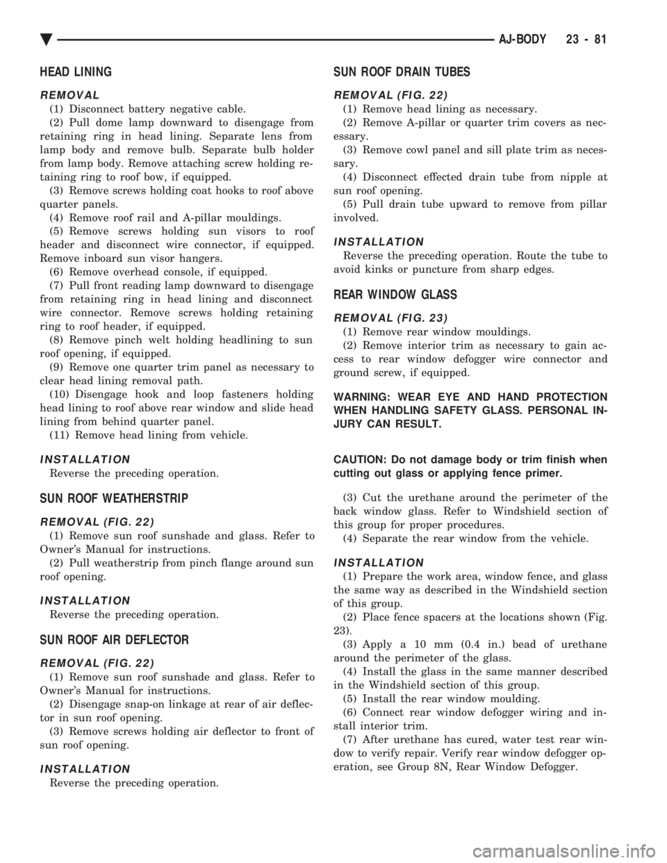
REMOVAL (FIG. 22)
(1) Remove sun roof sunshade and glass. Refer to
Owner's Manual for instructions. (2) Pull weatherstrip from pinch flange around sun
roof opening.
INSTALLATION
Reverse the preceding operation.
SUN ROOF AIR DEFLECTOR
REMOVAL (FIG. 22)
(1) Remove sun roof sunshade and glass. Refer to
Owner's Manual for instructions. (2) Disengage snap-on linkage at rear of air deflec-
tor in sun roof opening. (3) Remove screws holding air deflector to front of
sun roof opening.
INSTALLATION
Reverse the preceding operation.
SUN ROOF DRAIN TUBES
REMOVAL (FIG. 22)
(1) Remove head lining as necessary.
(2) Remove A-pillar or quarter trim covers as nec-
essary. (3) Remove cowl panel and sill plate trim as neces-
sary. (4) Disconnect effected drain tube from nipple at
sun roof opening. (5) Pull drain tube upward to remove from pillar
involved.
INSTALLATION
Reverse the preceding operation. Route the tube to
avoid kinks or puncture from sharp edges.
REAR WINDOW GLASS
REMOVAL (FIG. 23)
(1) Remove rear window mouldings.
(2) Remove interior trim as necessary to gain ac-
cess to rear window defogger wire connector and
ground screw, if equipped.
WARNING: WEAR EYE AND HAND PROTECTION
WHEN HANDLING SAFETY GLASS. PERSONAL IN-
JURY CAN RESULT.
CAUTION: Do not damage body or trim finish when
cutting out glass or applying fence primer.
(3) Cut the urethane around the perimeter of the
back window glass. Refer to Windshield section of
this group for proper procedures. (4) Separate the rear window from the vehicle.
INSTALLATION
(1) Prepare the work area, window fence, and glass
the same way as described in the Windshield section
of this group. (2) Place fence spacers at the locations shown (Fig.
23). (3) Apply a 10 mm (0.4 in.) bead of urethane
around the perimeter of the glass. (4) Install the glass in the same manner described
in the Windshield section of this group. (5) Install the rear window moulding.
(6) Connect rear window defogger wiring and in-
stall interior trim. (7) After urethane has cured, water test rear win-
dow to verify repair. Verify rear window defogger op-
eration, see Group 8N, Rear Window Defogger.
Ä AJ-BODY 23 - 81
Page 2248 of 2438
ADJUSTMENT PROCEDURES
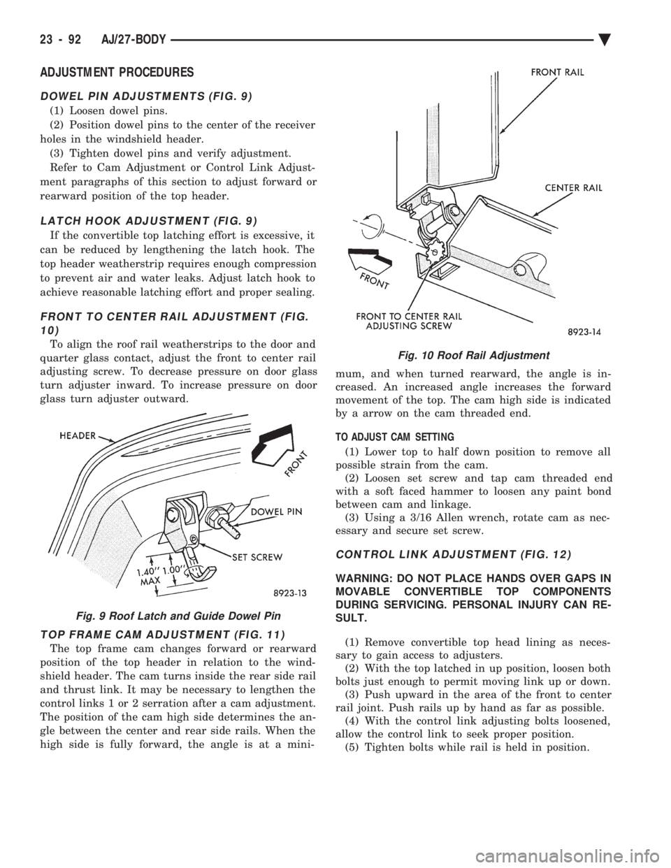
DOWEL PIN ADJUSTMENTS (FIG. 9)
(1) Loosen dowel pins.
(2) Position dowel pins to the center of the receiver
holes in the windshield header. (3) Tighten dowel pins and verify adjustment.
Refer to Cam Adjustment or Control Link Adjust-
ment paragraphs of this section to adjust forward or
rearward position of the top header.
LATCH HOOK ADJUSTMENT (FIG. 9)
If the convertible top latching effort is excessive, it
can be reduced by lengthening the latch hook. The
top header weatherstrip requires enough compression
to prevent air and water leaks. Adjust latch hook to
achieve reasonable latching effort and proper sealing.
FRONT TO CENTER RAIL ADJUSTMENT (FIG. 10)
To align the roof rail weatherstrips to the door and
quarter glass contact, adjust the front to center rail
adjusting screw. To decrease pressure on door glass
turn adjuster inward. To increase pressure on door
glass turn adjuster outward.
TOP FRAME CAM ADJUSTMENT (FIG. 11)
The top frame cam changes forward or rearward
position of the top header in relation to the wind-
shield header. The cam turns inside the rear side rail
and thrust link. It may be necessary to lengthen the
control links 1 or 2 serration after a cam adjustment.
The position of the cam high side determines the an-
gle between the center and rear side rails. When the
high side is fully forward, the angle is at a mini- mum, and when turned rearward, the angle is in-
creased. An increased angle increases the forward
movement of the top. The cam high side is indicated
by a arrow on the cam threaded end.
TO ADJUST CAM SETTING (1) Lower top to half down position to remove all
possible strain from the cam. (2) Loosen set screw and tap cam threaded end
with a soft faced hammer to loosen any paint bond
between cam and linkage. (3) Using a 3/16 Allen wrench, rotate cam as nec-
essary and secure set screw.
CONTROL LINK ADJUSTMENT (FIG. 12)
WARNING: DO NOT PLACE HANDS OVER GAPS IN
MOVABLE CONVERTIBLE TOP COMPONENTS
DURING SERVICING. PERSONAL INJURY CAN RE-
SULT.
(1) Remove convertible top head lining as neces-
sary to gain access to adjusters. (2) With the top latched in up position, loosen both
bolts just enough to permit moving link up or down. (3) Push upward in the area of the front to center
rail joint. Push rails up by hand as far as possible. (4) With the control link adjusting bolts loosened,
allow the control link to seek proper position. (5) Tighten bolts while rail is held in position.
Fig. 9 Roof Latch and Guide Dowel Pin
Fig. 10 Roof Rail Adjustment
23 - 92 AJ/27-BODY Ä
Page 2303 of 2438
REAR WINDOW GLASS
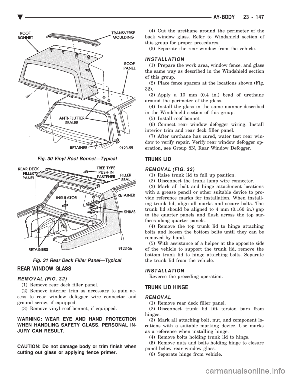
REMOVAL (FIG. 32)
(1) Remove rear deck filler panel.
(2) Remove interior trim as necessary to gain ac-
cess to rear window defogger wire connector and
ground screw, if equipped. (3) Remove vinyl roof bonnet, if equipped.
WARNING: WEAR EYE AND HAND PROTECTION
WHEN HANDLING SAFETY GLASS. PERSONAL IN-
JURY CAN RESULT.
CAUTION: Do not damage body or trim finish when
cutting out glass or applying fence primer. (4) Cut the urethane around the perimeter of the
back window glass. Refer to Windshield section of
this group for proper procedures. (5) Separate the rear window from the vehicle.
INSTALLATION
(1) Prepare the work area, window fence, and glass
the same way as described in the Windshield section
of this group. (2) Place fence spacers at the locations shown (Fig.
32). (3) Apply a 10 mm (0.4 in.) bead of urethane
around the perimeter of the glass. (4) Install the glass in the same manner described
in the Windshield section of this group. (5) Install roof bonnet.
(6) Connect rear window defogger wiring. Install
interior trim and rear deck filler panel. (7) After urethane has cured, water test rear win-
dow to verify repair. Verify rear window defogger op-
eration, see Group 8N, Rear Window Defogger.
TRUNK LID
REMOVAL (FIG. 33)
(1) Raise trunk lid to full up position.
(2) Disconnect the trunk lamp wire connector.
(3) Mark all bolt and hinge attachment locations
with a grease pencil or other suitable device to pro-
vide reference marks for installation. When install-
ing trunk lid, align all marks and secure bolts. The
trunk lid should be aligned to 4 mm (0.160 in.) gap
to the quarter panels and flush across the top sur-
faces along quarter panels. (4) Remove the top trunk lid to hinge attaching
bolts and loosen the bottom bolts until they can be
removed by hand. (5) With assistance of a helper at the opposite side
of the vehicle to support the trunk lid, remove the
bottom trunk lid to hinge attaching bolts. Separate
the trunk lid from the vehicle.
INSTALLATION
Reverse the preceding operation.
TRUNK LID HINGE
REMOVAL
(1) Remove rear deck filler panel.
(2) Disconnect trunk lid lift torsion bars from
hinges. (3) Mark all attaching bolt, nut, and component lo-
cations with a suitable marking device. Use marks
as a reference when installing hinge. (4) Remove bolts holding trunk lid to hinge.
(5) Remove nuts and bolts holding hinge to closure
panel below rear window glass. (6) Separate hinge from vehicle.
Fig. 30 Vinyl Roof BonnetÐTypical
Fig. 31 Rear Deck Filler PanelÐTypical
Ä AY-BODY 23 - 147
Page 2305 of 2438
HEATING AND AIR CONDITIONING
CONTENTS
page page
AUTOMATIC TEMPERATURE CONTROL (ATC) .............................. 66
COMPONENT SERVICE PROCEDURES ...... 47
FIXED DISPLACEMENT COMPRESSORÐ MODEL 10PA17 ...................... 24
FIXED DISPLACEMENT COMPRESSORÐ MODEL SD709P ...................... 38 FIXED DISPLACEMENT COMPRESSORÐ
MODEL TR105 ....................... 32
GENERAL INFORMATION .................. 1
HEATER AND A/C PERFORMANCE TESTS .... 6
REFRIGERANT SERVICE PROCEDURES ...... 8
VACUUM CONTROL SYSTEM DIAGNOSIS .... 4
VARIABLE DISPLACEMENT COMPRESSORÐ MODEL 6C17 ......................... 13
GENERAL INFORMATION INDEX
page page
A/C System Identification ................... 1
Cooling System Precautions ................. 3
Description and Operation ................... 1
Engine Cooling System Requirements .......... 2 Handling Tubing and Fittings
................. 3
Safety Precautions and Warnings ............. 3
Side Window Demisters .................... 2
System Airflow ........................... 1
A/C SYSTEM IDENTIFICATION
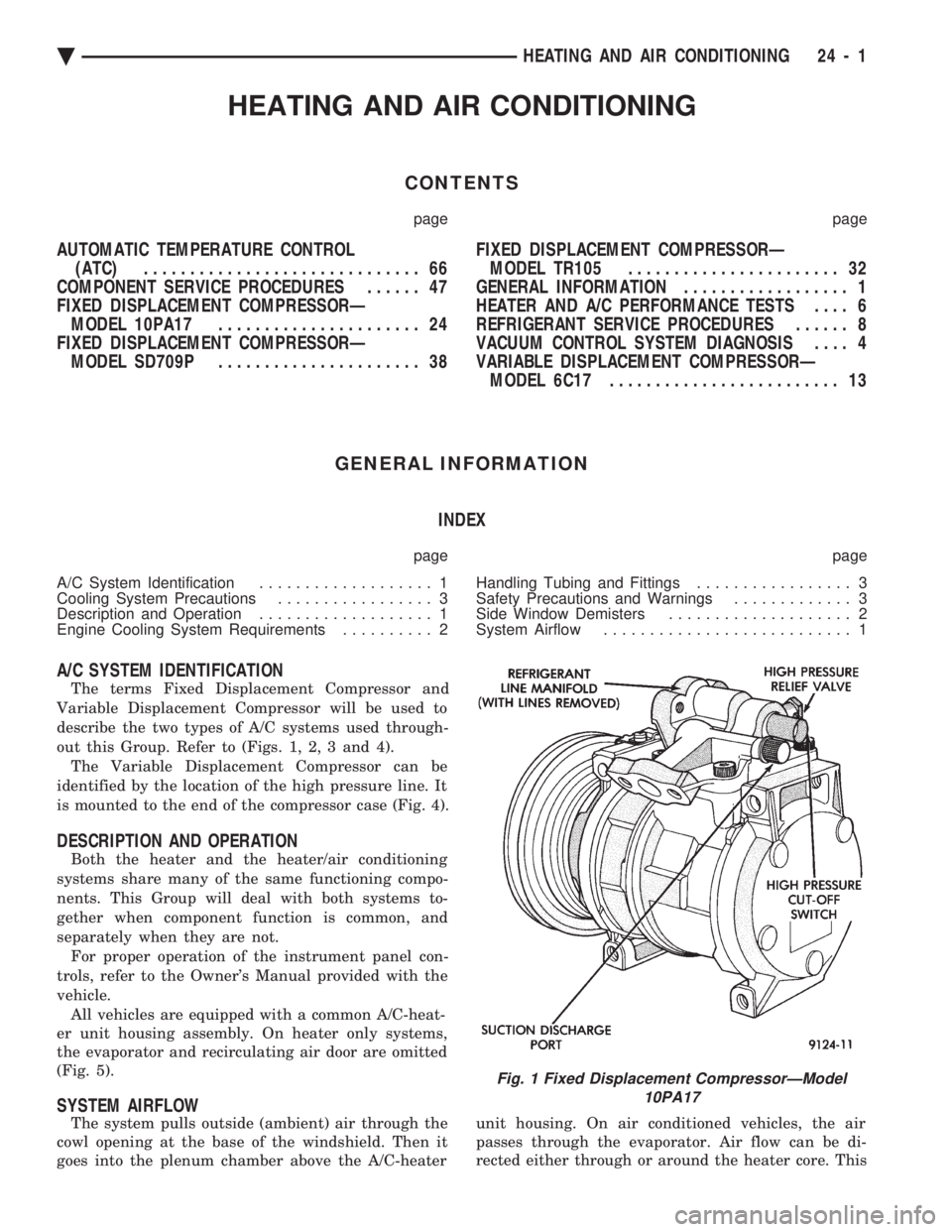
The terms Fixed Displacement Compressor and
Variable Displacement Compressor will be used to
describe the two types of A/C systems used through-
out this Group. Refer to (Figs. 1, 2, 3 and 4). The Variable Displacement Compressor can be
identified by the location of the high pressure line. It
is mounted to the end of the compressor case (Fig. 4).
DESCRIPTION AND OPERATION
Both the heater and the heater/air conditioning
systems share many of the same functioning compo-
nents. This Group will deal with both systems to-
gether when component function is common, and
separately when they are not. For proper operation of the instrument panel con-
trols, refer to the Owner's Manual provided with the
vehicle. All vehicles are equipped with a common A/C-heat-
er unit housing assembly. On heater only systems,
the evaporator and recirculating air door are omitted
(Fig. 5).
SYSTEM AIRFLOW
The system pulls outside (ambient) air through the
cowl opening at the base of the windshield. Then it
goes into the plenum chamber above the A/C-heater unit housing. On air conditioned vehicles, the air
passes through the evaporator. Air flow can be di-
rected either through or around the heater core. This
Fig. 1 Fixed Displacement CompressorÐModel 10PA17
Ä HEATING AND AIR CONDITIONING 24 - 1
Page 2307 of 2438
SAFETY PRECAUTIONS AND WARNINGS
WARNING: WEAR EYE PROTECTION WHEN SER-
VICING THE AIR CONDITIONING REFRIGERANT
SYSTEM. SERIOUS EYE INJURY CAN RESULT
FROM EYE CONTACT WITH REFRIGERANT. IF EYE
CONTACT IS MADE, SEEK MEDICAL ATTENTION
IMMEDIATELY. DO NOT EXPOSE REFRIGERANT TO OPEN
FLAME. POISONOUS GAS IS CREATED WHEN RE-
FRIGERANT IS BURNED. AN ELECTRONIC TYPE
LEAK DETECTOR IS RECOMMENDED. LARGE AMOUNTS OF REFRIGERANT RELEASED
IN A CLOSED WORK AREA WILL DISPLACE THE
OXYGEN AND CAUSE SUFFOCATION. THE EVAPORATION RATE OF (R-12) REFRIGER-
ANT AT AVERAGE TEMPERATURE AND ALTITUDE
IS EXTREMELY HIGH. AS A RESULT, ANYTHING
THAT COMES IN CONTACT WITH THE REFRIGER-
ANT WILL FREEZE. ALWAYS PROTECT SKIN OR
DELICATE OBJECTS FROM DIRECT CONTACT
WITH REFRIGERANT.
CAUTION: Liquid refrigerant is corrosive to metal
surfaces. Follow the operating instructions supplied
with equipment being used.
COOLING SYSTEM PRECAUTIONS
WARNING: ANTIFREEZE IS AN ETHYLENE GLYCOL
BASE COOLANT AND IS HARMFUL IF SWAL-
LOWED OR INHALED. IF SWALLOWED, DRINK
TWO GLASSES OF WATER AND INDUCE VOMIT-
ING. IF INHALED, MOVE TO FRESH AIR AREA.
SEEK MEDICAL ATTENTION IMMEDIATELY. DO NOT STORE IN OPEN OR UNMARKED CON-
TAINERS. WASH SKIN AND CLOTHING THOROUGHLY AF-
TER COMING IN CONTACT WITH ETHYLENE GLY-
COL. KEEP OUT OF REACH OF CHILDREN AND PETS.
DO NOT OPEN A COOLING SYSTEM WHEN THE
ENGINE IS AT RUNNING TEMPERATURE. PER-
SONAL INJURY CAN RESULT.
The engine cooling system is designed to develop
internal pressure of 97 to 123 kPa (14 to 18 psi). Al-
low the vehicle 15 minutes (or until a safe tempera-
ture and pressure are attained) before opening the
cooling system. Refer to Group 7, Cooling System.
HANDLING TUBING AND FITTINGS
Kinks in the refrigerant tubing or sharp bends in
the refrigerant hose lines will greatly reduce the ca-
pacity of the entire system. High pressures are pro-
duced in the system when it is operating. Extreme
care must be exercised to make sure that all connec-
tions are pressure tight. Dirt and moisture can enter
the system when it is opened for repair or replace-
ment of lines or components. The refrigerant oil will
absorb moisture readily out of the air. This moisture
will convert into acids within a closed system. The following precautions must be observed:
The system must be completely empty before open-
ing any fitting or connection in the refrigeration sys-
tem. Open fittings with caution even after the
system has been emptied. If any pressure is noticed
as a fitting is loosened, allow trapped pressure to
bleed off very slowly. A good rule for the flexible hose lines is to keep the
radius of all bends at least 10 times the diameter of
the hose. Sharper bends will reduce the flow of re-
frigerant. The flexible hose lines should be routed so
they are at least 3 inches (80 mm) from the exhaust
manifold. Inspect all flexible hose lines to make sure
they are in good condition and properly routed. Unified plumbing connections with aluminum gas-
kets cannot be serviced with O-rings. These gaskets
are not reusable and do not require lubrication be-
fore installing. The use of correct wrenches when making connec-
tions is very important. Improper wrenches or im-
proper use of wrenches can damage the fittings. The A/C system will remain chemical stabile as
long as pure-moisture-free R-12 and refrigerant oil is
used. Abnormal amounts of dirt, moisture or air can
upset the chemical stability. This condition could
cause operational troubles or even serious damage if
present in more than very small quantities. When it is necessary to open the refrigeration sys-
tem, have everything needed to service the system
ready. The system should not be left open any longer
than necessary. Cap or plug all lines and fittings as
soon as they are opened to prevent the entrance or
dirt and moisture. All lines and components in parts
stock should be capped or sealed until they are ready
to be used. All tools, including the refrigerant dispensing man-
ifold, the manifold gauge set, and test hoses should
be kept clean and dry.
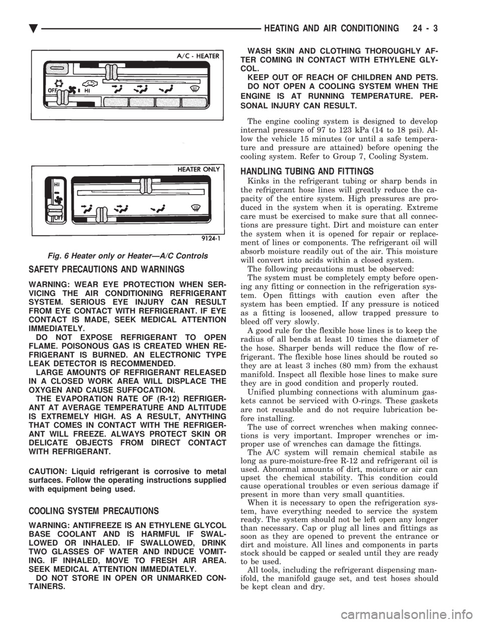
Fig. 6 Heater only or HeaterÐA/C Controls
Ä HEATING AND AIR CONDITIONING 24 - 3
Page 2310 of 2438
HEATER AND A/C PERFORMANCE TESTS
HEATER OUTPUT TEST
PRE-DIAGNOSTIC PREPARATIONS
Review Safety Precautions and Warnings before
performing the following procedures. Check the radiator coolant level, drive belt tension,
and engine vacuum line connections. Also check ra-
diator air flow and radiator fan operation. Start en-
gine and allow to warm up to normal operating
temperature.
WARNING: DO NOT REMOVE RADIATOR CAP
WHEN ENGINE IS HOT, PERSONAL INJURY CAN
RESULT.
If vehicle has been run recently, wait 15 minutes
before removing cap. Place a rag over the cap and
turn it to the first safety stop. Allow pressure to es-
cape through the overflow tube. When the system
stabilizes, remove the cap completely.
MAXIMUM HEATER OUTPUT: TEST AND ACTION
Engine coolant is provided to the heater system by
two 16 mm (5/8 inch inside diameter) heater hoses.
With engine idling at normal running temperature,
set the control to maximum heat, floor, and high
blower setting. Using a test thermometer, check the
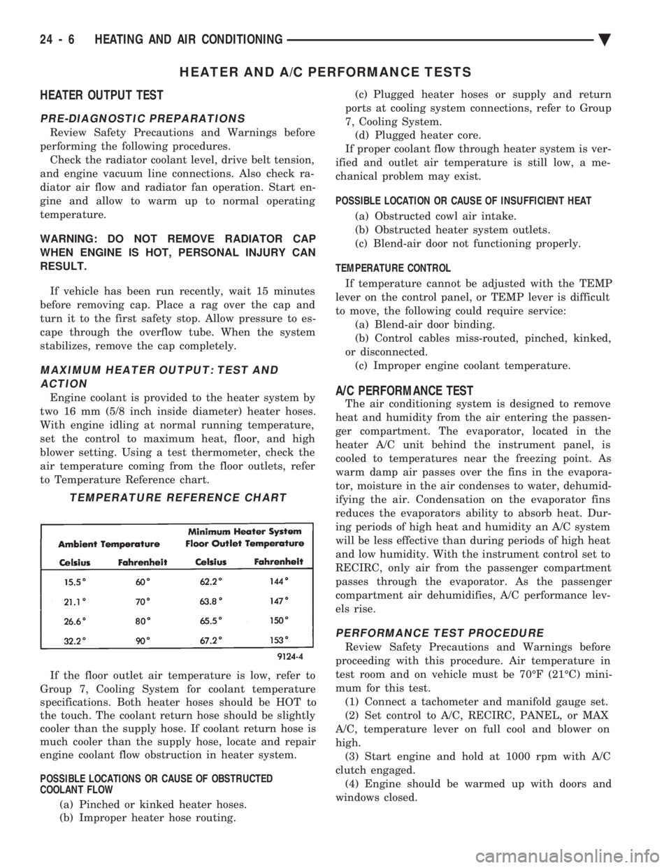
air temperature coming from the floor outlets, refer
to Temperature Reference chart.
If the floor outlet air temperature is low, refer to
Group 7, Cooling System for coolant temperature
specifications. Both heater hoses should be HOT to
the touch. The coolant return hose should be slightly
cooler than the supply hose. If coolant return hose is
much cooler than the supply hose, locate and repair
engine coolant flow obstruction in heater system.
POSSIBLE LOCATIONS OR CAUSE OF OBSTRUCTED
COOLANT FLOW
(a) Pinched or kinked heater hoses.
(b) Improper heater hose routing. (c) Plugged heater hoses or supply and return
ports at cooling system connections, refer to Group
7, Cooling System. (d) Plugged heater core.
If proper coolant flow through heater system is ver-
ified and outlet air temperature is still low, a me-
chanical problem may exist.
POSSIBLE LOCATION OR CAUSE OF INSUFFICIENT HEAT
(a) Obstructed cowl air intake.
(b) Obstructed heater system outlets.
(c) Blend-air door not functioning properly.
TEMPERATURE CONTROL If temperature cannot be adjusted with the TEMP
lever on the control panel, or TEMP lever is difficult
to move, the following could require service: (a) Blend-air door binding.
(b) Control cables miss-routed, pinched, kinked,
or disconnected. (c) Improper engine coolant temperature.A/C PERFORMANCE TEST
The air conditioning system is designed to remove
heat and humidity from the air entering the passen-
ger compartment. The evaporator, located in the
heater A/C unit behind the instrument panel, is
cooled to temperatures near the freezing point. As
warm damp air passes over the fins in the evapora-
tor, moisture in the air condenses to water, dehumid-
ifying the air. Condensation on the evaporator fins
reduces the evaporators ability to absorb heat. Dur-
ing periods of high heat and humidity an A/C system
will be less effective than during periods of high heat
and low humidity. With the instrument control set to
RECIRC, only air from the passenger compartment
passes through the evaporator. As the passenger
compartment air dehumidifies, A/C performance lev-
els rise.
PERFORMANCE TEST PROCEDURE
Review Safety Precautions and Warnings before
proceeding with this procedure. Air temperature in
test room and on vehicle must be 70ÉF (21ÉC) mini-
mum for this test. (1) Connect a tachometer and manifold gauge set.
(2) Set control to A/C, RECIRC, PANEL, or MAX
A/C, temperature lever on full cool and blower on
high. (3) Start engine and hold at 1000 rpm with A/C
clutch engaged. (4) Engine should be warmed up with doors and
windows closed.
TEMPERATURE REFERENCE CHART
24 - 6 HEATING AND AIR CONDITIONING Ä
Page 2312 of 2438
REFRIGERANT SERVICE PROCEDURES INDEX
page page
Adding Partial Refrigerant Charge ............ 10
Charging Refrigerant SystemÐEmpty System . . . 11
Discharging Refrigerant System .............. 11
Evacuating Refrigerant System .............. 11
Manifold Gauge Set Connections ............. 9 Oil Level
............................... 12
R-12 Refrigerant Equipment ................. 8
Refrigerant Recycling ...................... 9
Sight Glass Refrigerant Level Inspection ........ 8
Testing for Refrigerant Leaks ............... 10
SIGHT GLASS REFRIGERANT LEVEL INSPECTION
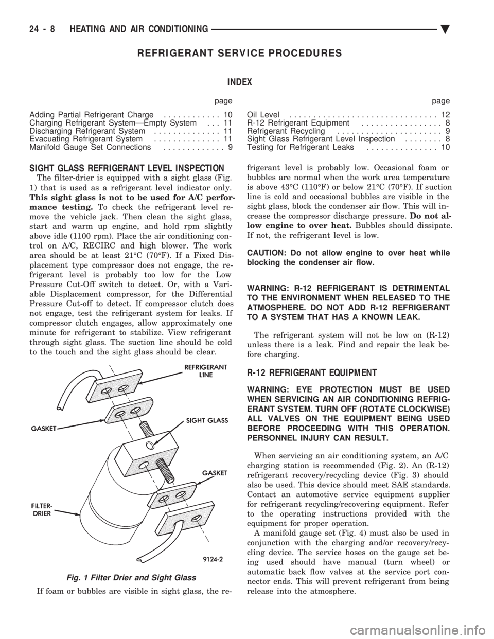
The filter-drier is equipped with a sight glass (Fig.
1) that is used as a refrigerant level indicator only.
This sight glass is not to be used for A/C perfor-
mance testing. To check the refrigerant level re-
move the vehicle jack. Then clean the sight glass,
start and warm up engine, and hold rpm slightly
above idle (1100 rpm). Place the air conditioning con-
trol on A/C, RECIRC and high blower. The work
area should be at least 21ÉC (70ÉF). If a Fixed Dis-
placement type compressor does not engage, the re-
frigerant level is probably too low for the Low
Pressure Cut-Off switch to detect. Or, with a Vari-
able Displacement compressor, for the Differential
Pressure Cut-off to detect. If compressor clutch does
not engage, test the refrigerant system for leaks. If
compressor clutch engages, allow approximately one
minute for refrigerant to stabilize. View refrigerant
through sight glass. The suction line should be cold
to the touch and the sight glass should be clear.
If foam or bubbles are visible in sight glass, the re- frigerant level is probably low. Occasional foam or
bubbles are normal when the work area temperature
is above 43ÉC (110ÉF) or below 21ÉC (70ÉF). If suction
line is cold and occasional bubbles are visible in the
sight glass, block the condenser air flow. This will in-
crease the compressor discharge pressure. Do not al-
low engine to over heat. Bubbles should dissipate.
If not, the refrigerant level is low.
CAUTION: Do not allow engine to over heat while
blocking the condenser air flow.
WARNING: R-12 REFRIGERANT IS DETRIMENTAL
TO THE ENVIRONMENT WHEN RELEASED TO THE
ATMOSPHERE. DO NOT ADD R-12 REFRIGERANT
TO A SYSTEM THAT HAS A KNOWN LEAK.
The refrigerant system will not be low on (R-12)
unless there is a leak. Find and repair the leak be-
fore charging.
R-12 REFRIGERANT EQUIPMENT
WARNING: EYE PROTECTION MUST BE USED
WHEN SERVICING AN AIR CONDITIONING REFRIG-
ERANT SYSTEM. TURN OFF (ROTATE CLOCKWISE)
ALL VALVES ON THE EQUIPMENT BEING USED
BEFORE PROCEEDING WITH THIS OPERATION.
PERSONNEL INJURY CAN RESULT.
When servicing an air conditioning system, an A/C
charging station is recommended (Fig. 2). An (R-12)
refrigerant recovery/recycling device (Fig. 3) should
also be used. This device should meet SAE standards.
Contact an automotive service equipment supplier
for refrigerant recycling/recovering equipment. Refer
to the operating instructions provided with the
equipment for proper operation. A manifold gauge set (Fig. 4) must also be used in
conjunction with the charging and/or recovery/recy-
cling device. The service hoses on the gauge set be-
ing used should have manual (turn wheel) or
automatic back flow valves at the service port con-
nector ends. This will prevent refrigerant from being
release into the atmosphere.
Fig. 1 Filter Drier and Sight Glass
24 - 8 HEATING AND AIR CONDITIONING Ä