1993 CHEVROLET DYNASTY warning
[x] Cancel search: warningPage 1914 of 2438
WARNING: PLACE A SHOP TOWEL UNDER FUEL
PRESSURE REGULATOR TO ABSORB ANY FUEL
SPILLAGE.
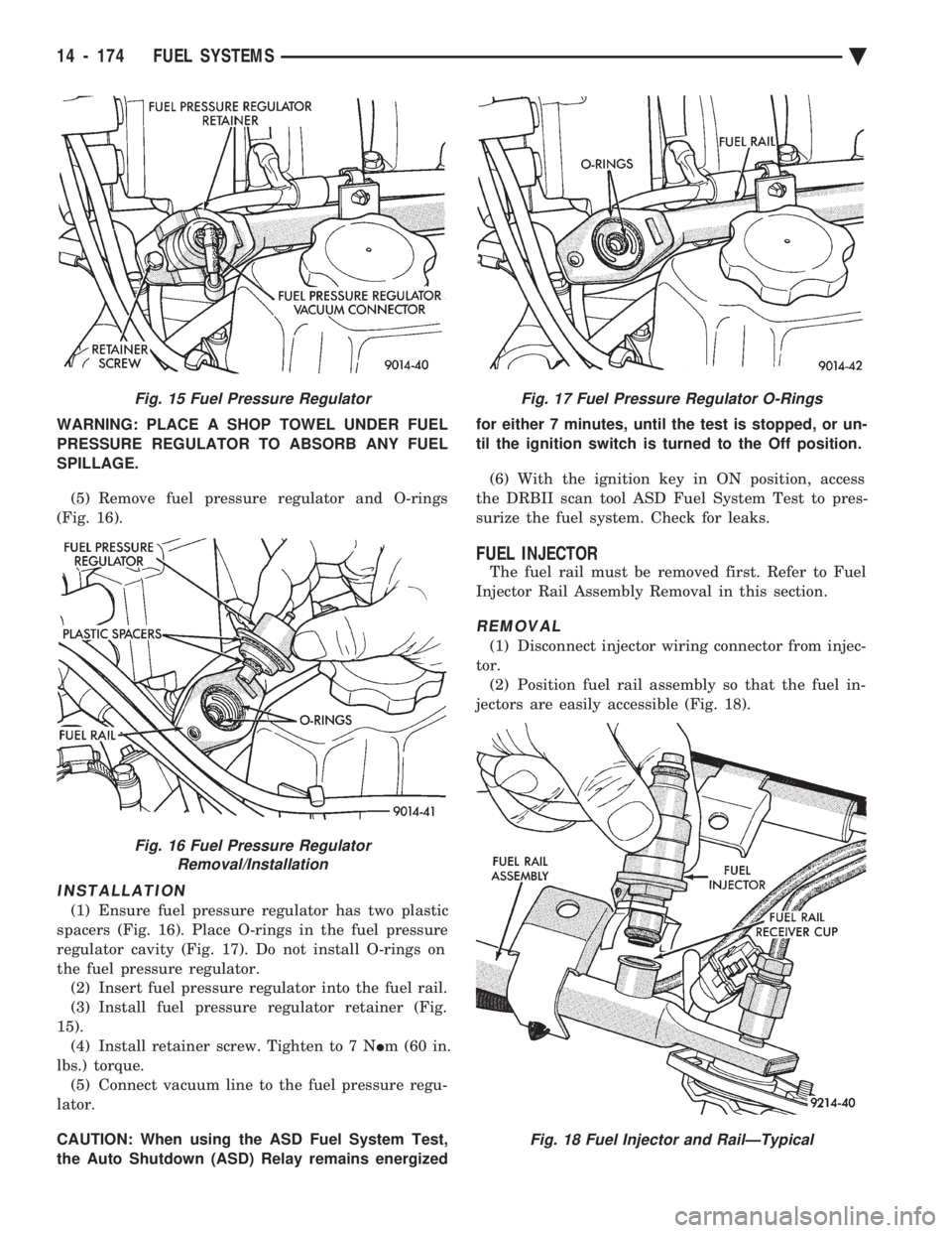
(5) Remove fuel pressure regulator and O-rings
(Fig. 16).
INSTALLATION
(1) Ensure fuel pressure regulator has two plastic
spacers (Fig. 16). Place O-rings in the fuel pressure
regulator cavity (Fig. 17). Do not install O-rings on
the fuel pressure regulator. (2) Insert fuel pressure regulator into the fuel rail.
(3) Install fuel pressure regulator retainer (Fig.
15). (4) Install retainer screw. Tighten to 7 N Im (60 in.
lbs.) torque. (5) Connect vacuum line to the fuel pressure regu-
lator.
CAUTION: When using the ASD Fuel System Test,
the Auto Shutdown (ASD) Relay remains energized for either 7 minutes, until the test is stopped, or un-
til the ignition switch is turned to the Off position.
(6) With the ignition key in ON position, access
the DRBII scan tool ASD Fuel System Test to pres-
surize the fuel system. Check for leaks.
FUEL INJECTOR
The fuel rail must be removed first. Refer to Fuel
Injector Rail Assembly Removal in this section.
REMOVAL
(1) Disconnect injector wiring connector from injec-
tor. (2) Position fuel rail assembly so that the fuel in-
jectors are easily accessible (Fig. 18).
Fig. 15 Fuel Pressure Regulator
Fig. 16 Fuel Pressure Regulator Removal/Installation
Fig. 17 Fuel Pressure Regulator O-Rings
Fig. 18 Fuel Injector and RailÐTypical
14 - 174 FUEL SYSTEMS Ä
Page 1917 of 2438
is made with the camshaft gear. While holding the
sensor in this position, install and tighten the retain-
ing bolt 12 N Im (105 in. lbs.) torque.
(2) Connect camshaft position sensor electrical con-
nector to harness connector. Position connector away
from the accessory belt.
HEATED OXYGEN SENSOR (O2SENSOR) SERVICE
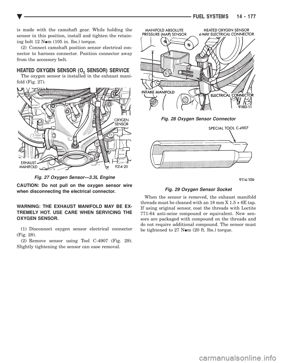
The oxygen sensor is installed in the exhaust mani-
fold (Fig. 27).
CAUTION: Do not pull on the oxygen sensor wire
when disconnecting the electrical connector.
WARNING: THE EXHAUST MANIFOLD MAY BE EX-
TREMELY HOT. USE CARE WHEN SERVICING THE
OXYGEN SENSOR.
(1) Disconnect oxygen sensor electrical connector
(Fig. 28). (2) Remove sensor using Tool C-4907 (Fig. 29).
Slightly tightening the sensor can ease removal. When the sensor is removed, the exhaust manifold
threads must be cleaned with an 18 mm X 1.5 + 6E tap.
If using original sensor, coat the threads with Loctite
771-64 anti-seize compound or equivalent. New sen-
sors are packaged with compound on the threads and
do not require additional compound. The sensor must
be tightened to 27 N Im (20 ft. lbs.) torque.
Fig. 27 Oxygen SensorÐ3.3L Engine
Fig. 28 Oxygen Sensor Connector
Fig. 29 Oxygen Sensor Socket
Ä FUEL SYSTEMS 14 - 177
Page 1927 of 2438
When steering conditions exceed maximum pres-
sure requirements, such as when the wheels are
turned against the stops. The pressure built up in
the steering gear exerts pressure on the spring end of
the flow control valve. The high pressure lifts the re-
lief valve ball from its seat and allows oil to flow
through a trigger orifice located in the outlet fitting.
This reduces pressure on the spring end of the flow
control valve which then opens and allows the oil to
return to the intake side of the pump. This action
limits maximum pressure output of the pump to a
safe level. Under normal power steering pump operating con-
ditions, pressure requirements of the pump are below
maximum, causing the pressure relief valve to re-
main closed.
CHECKING POWER STEERING FLUID LEVEL
WARNING: FLUID LEVEL SHOULD BE CHECKED
WITH ENGINE OFF TO PREVENT INJURY FROM
MOVING PARTS. DO NOT USE AUTOMATIC TRANS-
MISSION FLUID IN THE POWER STEERING SYS-
TEM. DO NOT OVERFILL THE POWER STEERING
SYSTEM.
Wipe reservoir filler cap free of dirt, before check-
ing power steering fluid level. The dipstick should in- dicate FULL COLD when fluid is at normal ambient
temperature, approximately 21ÉC to 27ÉC (70ÉF to
80ÉF). In all pumps add fluid as necessary to obtain
proper level, using only MopartPower Steering
Fluid, or equivalent. DO NOT USE ANY TYPE
OF AUTOMATIC TRANSMISSION FLUID.
POWER STEERING PUMP PRESSURE TEST
The following procedure can be used to test the op-
eration of the power steering system on the vehicle. (1) Check power steering pump drive belt tension
and adjust as necessary. (2) Disconnect power steering fluid pressure hose,
at steering gear or power steering pump. Use a con-
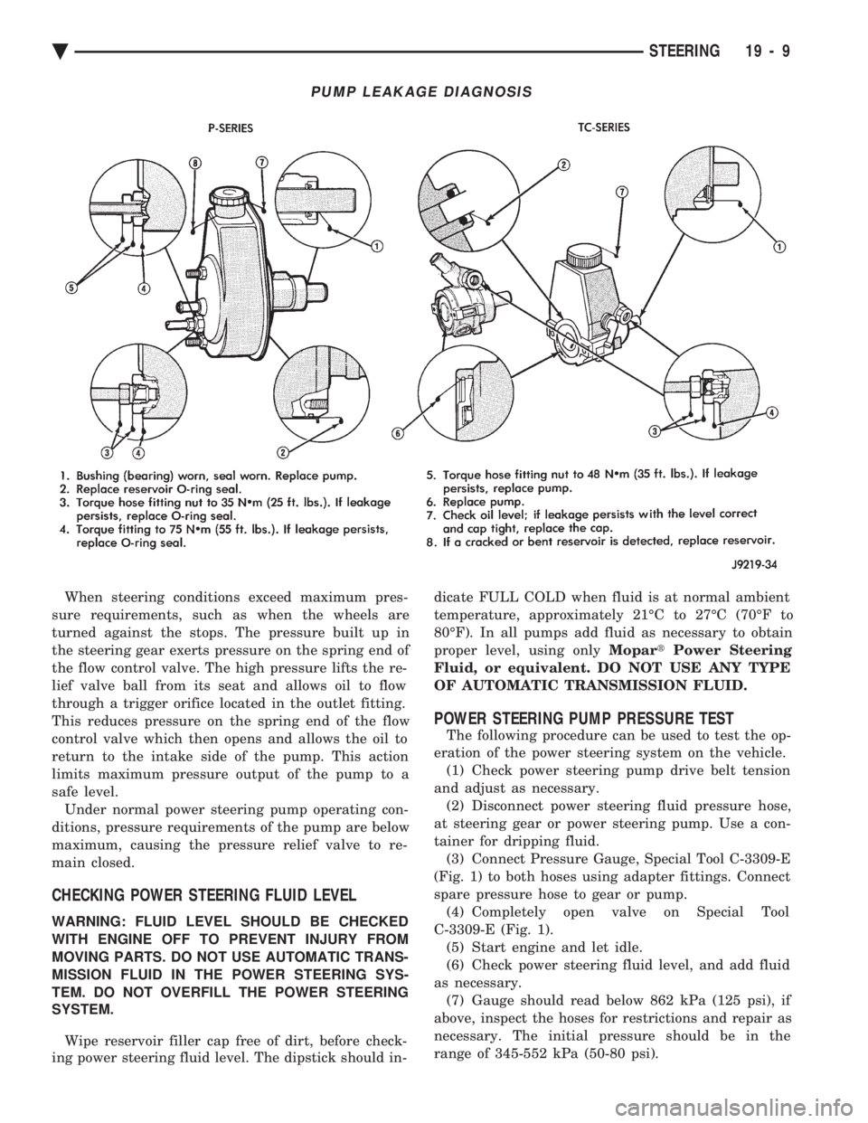
tainer for dripping fluid. (3) Connect Pressure Gauge, Special Tool C-3309-E
(Fig. 1) to both hoses using adapter fittings. Connect
spare pressure hose to gear or pump. (4) Completely open valve on Special Tool
C-3309-E (Fig. 1). (5) Start engine and let idle.
(6) Check power steering fluid level, and add fluid
as necessary. (7) Gauge should read below 862 kPa (125 psi), if
above, inspect the hoses for restrictions and repair as
necessary. The initial pressure should be in the
range of 345-552 kPa (50-80 psi).
PUMP LEAKAGE DIAGNOSIS
Ä STEERING 19 - 9
Page 1929 of 2438
INSTALL
(1) Install power steering pressure switch into fit-
ting on power steering pressure hose by hand until
fully seated. Then torque power steering pressure
switch to 12 N Im (106 in. lbs.).
(2) Install vehicle wiring harness connector onto
power steering pressure switch. Be sure latch on wir-
ing harness connector is fully engaged with locking
tab on power steering pressure switch.
CAUTION: Do not use automatic transmission fluid
in power steering system. Only use Mopar T, Power
Steering Fluid, or equivalent.
(3) Fill power steering pump reservoir to correct
fluid level. (4) Connect negative cable back on negative post of
battery. (5) Start engine and turn steering wheel several
times from stop to stop to bleed air from fluid in sys-
tem. Stop engine, check fluid level, and inspect sys-
tem for leaks. See Checking Fluid Level.
POWER STEERING HOSES
Service all power steering hoses with the vehicle
raised on a hoist. Cap all open ends of hoses, power
steering pump fittings and steering gear ports to pre-
vent entry of foreign material into the components.
WARNING: POWER STEERING OIL, ENGINE PARTS
AND EXHAUST SYSTEM MAY BE EXTREMELY HOT
IF ENGINE HAS BEEN RUNNING. DO NOT START
ENGINE WITH ANY LOOSE OR DISCONNECTED
HOSES. DO NOT ALLOW HOSES TO TOUCH HOT
EXHAUST MANIFOLD OR CATALYST.
For part reference and part location on the vehicle
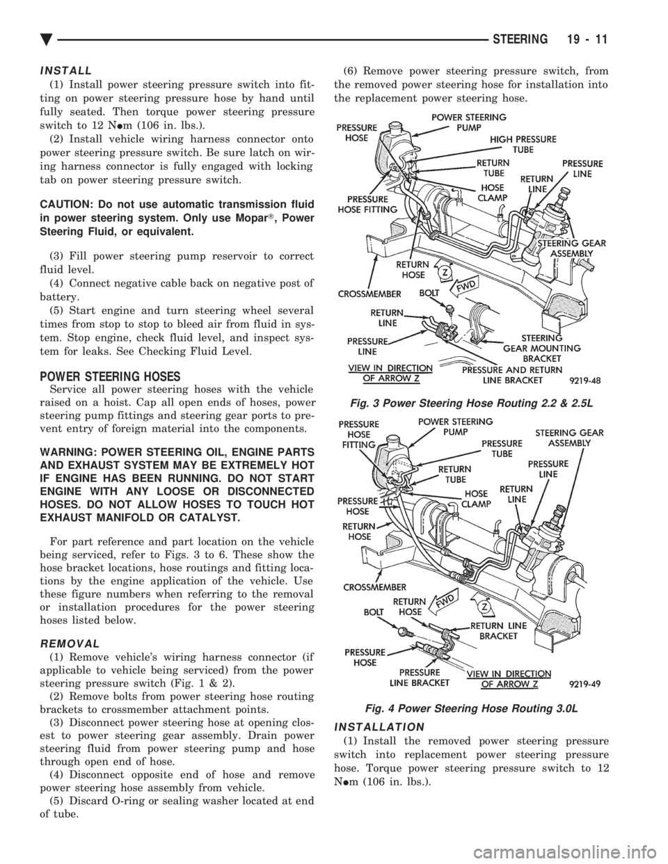
being serviced, refer to Figs. 3 to 6. These show the
hose bracket locations, hose routings and fitting loca-
tions by the engine application of the vehicle. Use
these figure numbers when referring to the removal
or installation procedures for the power steering
hoses listed below.
REMOVAL
(1) Remove vehicle's wiring harness connector (if
applicable to vehicle being serviced) from the power
steering pressure switch (Fig .1&2).
(2) Remove bolts from power steering hose routing
brackets to crossmember attachment points. (3) Disconnect power steering hose at opening clos-
est to power steering gear assembly. Drain power
steering fluid from power steering pump and hose
through open end of hose. (4) Disconnect opposite end of hose and remove
power steering hose assembly from vehicle. (5) Discard O-ring or sealing washer located at end
of tube. (6) Remove power steering pressure switch, from
the removed power steering hose for installation into
the replacement power steering hose.
INSTALLATION
(1) Install the removed power steering pressure
switch into replacement power steering pressure
hose. Torque power steering pressure switch to 12
N Im (106 in. lbs.).
Fig. 3 Power Steering Hose Routing 2.2 & 2.5L
Fig. 4 Power Steering Hose Routing 3.0L
Ä STEERING 19 - 11
Page 1930 of 2438
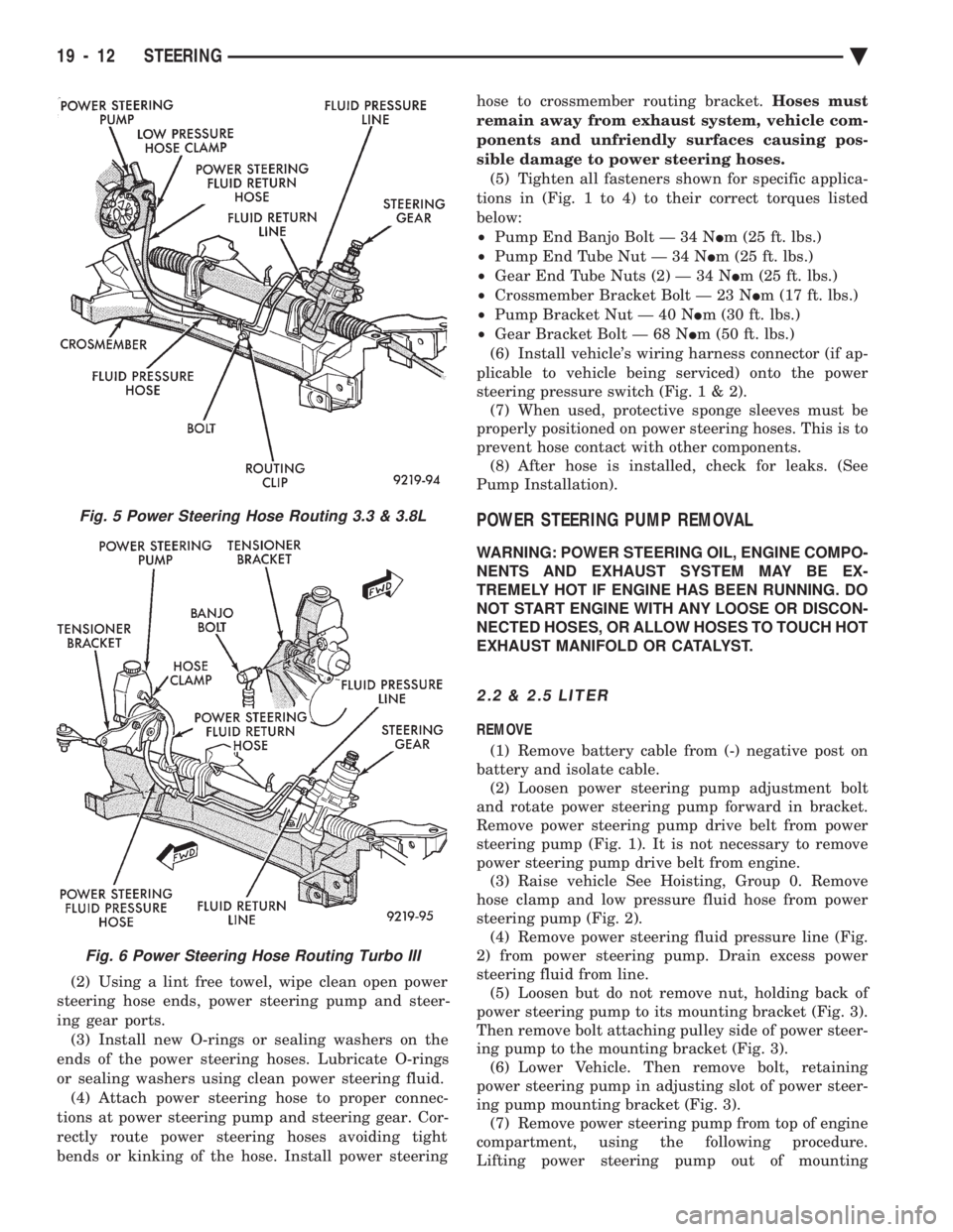
(2) Using a lint free towel, wipe clean open power
steering hose ends, power steering pump and steer-
ing gear ports. (3) Install new O-rings or sealing washers on the
ends of the power steering hoses. Lubricate O-rings
or sealing washers using clean power steering fluid. (4) Attach power steering hose to proper connec-
tions at power steering pump and steering gear. Cor-
rectly route power steering hoses avoiding tight
bends or kinking of the hose. Install power steering hose to crossmember routing bracket.
Hoses must
remain away from exhaust system, vehicle com-
ponents and unfriendly surfaces causing pos-
sible damage to power steering hoses. (5) Tighten all fasteners shown for specific applica-
tions in (Fig. 1 to 4) to their correct torques listed
below:
² Pump End Banjo Bolt Ð 34 N Im (25 ft. lbs.)
² Pump End Tube Nut Ð 34 N Im (25 ft. lbs.)
² Gear End Tube Nuts (2) Ð 34 N Im (25 ft. lbs.)
² Crossmember Bracket Bolt Ð 23 N Im (17 ft. lbs.)
² Pump Bracket Nut Ð 40 N Im (30 ft. lbs.)
² Gear Bracket Bolt Ð 68 N Im (50 ft. lbs.)
(6) Install vehicle's wiring harness connector (if ap-
plicable to vehicle being serviced) onto the power
steering pressure switch (Fig .1&2).
(7) When used, protective sponge sleeves must be
properly positioned on power steering hoses. This is to
prevent hose contact with other components. (8) After hose is installed, check for leaks. (See
Pump Installation).
POWER STEERING PUMP REMOVAL
WARNING: POWER STEERING OIL, ENGINE COMPO-
NENTS AND EXHAUST SYSTEM MAY BE EX-
TREMELY HOT IF ENGINE HAS BEEN RUNNING. DO
NOT START ENGINE WITH ANY LOOSE OR DISCON-
NECTED HOSES, OR ALLOW HOSES TO TOUCH HOT
EXHAUST MANIFOLD OR CATALYST.
2.2 & 2.5 LITER
REMOVE
(1) Remove battery cable from (-) negative post on
battery and isolate cable. (2) Loosen power steering pump adjustment bolt
and rotate power steering pump forward in bracket.
Remove power steering pump drive belt from power
steering pump (Fig. 1). It is not necessary to remove
power steering pump drive belt from engine. (3) Raise vehicle See Hoisting, Group 0. Remove
hose clamp and low pressure fluid hose from power
steering pump (Fig. 2). (4) Remove power steering fluid pressure line (Fig.
2) from power steering pump. Drain excess power
steering fluid from line. (5) Loosen but do not remove nut, holding back of
power steering pump to its mounting bracket (Fig. 3).
Then remove bolt attaching pulley side of power steer-
ing pump to the mounting bracket (Fig. 3). (6) Lower Vehicle. Then remove bolt, retaining
power steering pump in adjusting slot of power steer-
ing pump mounting bracket (Fig. 3). (7) Remove power steering pump from top of engine
compartment, using the following procedure.
Lifting power steering pump out of mounting
Fig. 5 Power Steering Hose Routing 3.3 & 3.8L
Fig. 6 Power Steering Hose Routing Turbo III
19 - 12 STEERING Ä
Page 1946 of 2438
ACUSTAR STANDARD AND TILT STEERING COLUMN INDEX
page page
General Information ....................... 28
Ignition Switch Service .................... 34 Steering Column Component Service
......... 34
Steering Column Service Procedures .......... 30
GENERAL INFORMATION
WARNING: THE AIR BAG SYSTEM IS A SENSITIVE,
COMPLEX ELECTRO-MECHANICAL UNIT. BEFORE
ATTEMPTING TO DIAGNOSE, REMOVE OR IN-
STALL THE AIR BAG SYSTEM COMPONENTS YOU
MUST FIRST DISCONNECT AND ISOLATE THE
BATTERY NEGATIVE (GROUND) CABLE. FAILURE
TO DO SO COULD RESULT IN ACCIDENTAL DE-
PLOYMENT OF THE AIR BAG AND POSSIBLE PER-
SONAL INJURY. THE FASTENERS, SCREWS, AND BOLTS, ORIGI-
NALLY USED FOR THE AIR BAG COMPONENTS,
HAVE SPECIAL COATINGS AND ARE SPECIFI- CALLY DESIGNED FOR THE AIR BAG SYSTEM.
THEY MUST NEVER BE REPLACED WITH ANY
SUBSTITUTES. ANYTIME A NEW FASTENER IS
NEEDED, REPLACE WITH THE CORRECT FASTEN-
ERS PROVIDED IN THE SERVICE PACKAGE OR
FASTENERS LISTED IN THE PARTS BOOKS. BEFORE SERVICING A STEERING COLUMN
EQUIPPED WITH AN AIR BAG, REFER TO GROUP
8M, ELECTRICAL FOR PROPER AND SAFE SER-
VICE PROCEDURES.
Safety goggles should be worn at all times
when working on steering columns.
19 - 28 STEERING Ä
Page 1948 of 2438
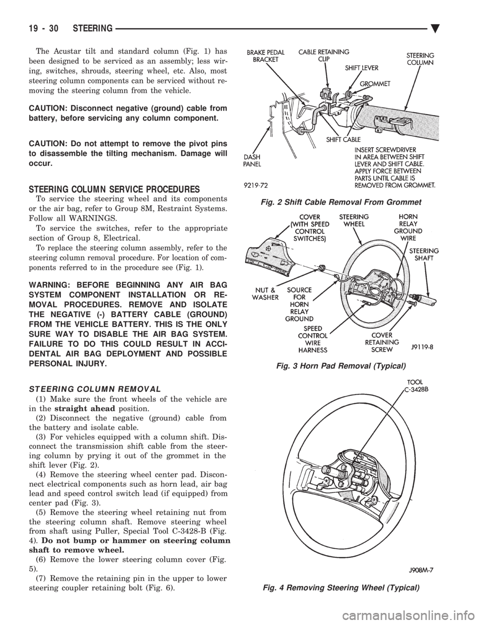
The Acustar tilt and standard column (Fig. 1) has
been designed to be serviced as an assembly; less wir-
ing, switches, shrouds, steering wheel, etc. Also, most
steering column components can be serviced without re-
moving the steering column from the vehicle.
CAUTION: Disconnect negative (ground) cable from
battery, before servicing any column component.
CAUTION: Do not attempt to remove the pivot pins
to disassemble the tilting mechanism. Damage will
occur.
STEERING COLUMN SERVICE PROCEDURES
To service the steering wheel and its components
or the air bag, refer to Group 8M, Restraint Systems.
Follow all WARNINGS. To service the switches, refer to the appropriate
section of Group 8, Electrical.
To replace the steering column assembly, refer to the
steering column removal procedure. For location of com-
ponents referred to in the procedure see (Fig. 1).
WARNING: BEFORE BEGINNING ANY AIR BAG
SYSTEM COMPONENT INSTALLATION OR RE-
MOVAL PROCEDURES. REMOVE AND ISOLATE
THE NEGATIVE (-) BATTERY CABLE (GROUND)
FROM THE VEHICLE BATTERY. THIS IS THE ONLY
SURE WAY TO DISABLE THE AIR BAG SYSTEM.
FAILURE TO DO THIS COULD RESULT IN ACCI-
DENTAL AIR BAG DEPLOYMENT AND POSSIBLE
PERSONAL INJURY.
STEERING COLUMN REMOVAL
(1) Make sure the front wheels of the vehicle are
in the straight ahead position.
(2) Disconnect the negative (ground) cable from
the battery and isolate cable. (3) For vehicles equipped with a column shift. Dis-
connect the transmission shift cable from the steer-
ing column by prying it out of the grommet in the
shift lever (Fig. 2). (4) Remove the steering wheel center pad. Discon-
nect electrical components such as horn lead, air bag
lead and speed control switch lead (if equipped) from
center pad (Fig. 3). (5) Remove the steering wheel retaining nut from
the steering column shaft. Remove steering wheel
from shaft using Puller, Special Tool C-3428-B (Fig.
4). Do not bump or hammer on steering column
shaft to remove wheel. (6) Remove the lower steering column cover (Fig.
5). (7) Remove the retaining pin in the upper to lower
steering coupler retaining bolt (Fig. 6).
Fig. 2 Shift Cable Removal From Grommet
Fig. 3 Horn Pad Removal (Typical)
Fig. 4 Removing Steering Wheel (Typical)
19 - 30 STEERING Ä
Page 2038 of 2438
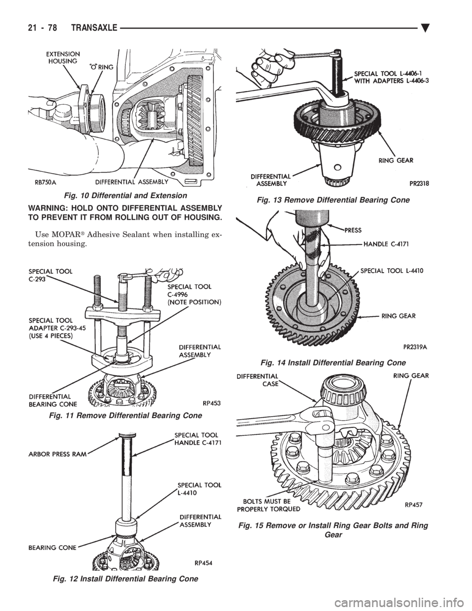
WARNING: HOLD ONTO DIFFERENTIAL ASSEMBLY
TO PREVENT IT FROM ROLLING OUT OF HOUSING.
Use MOPAR tAdhesive Sealant when installing ex-
tension housing.
Fig. 10 Differential and Extension
Fig. 11 Remove Differential Bearing Cone
Fig. 12 Install Differential Bearing Cone
Fig. 13 Remove Differential Bearing Cone
Fig. 14 Install Differential Bearing Cone
Fig. 15 Remove or Install Ring Gear Bolts and Ring Gear
21 - 78 TRANSAXLE Ä