Page 2403 of 2438

POSITIVE CRANKCASE VENTILATION (PCV)
SYSTEMS
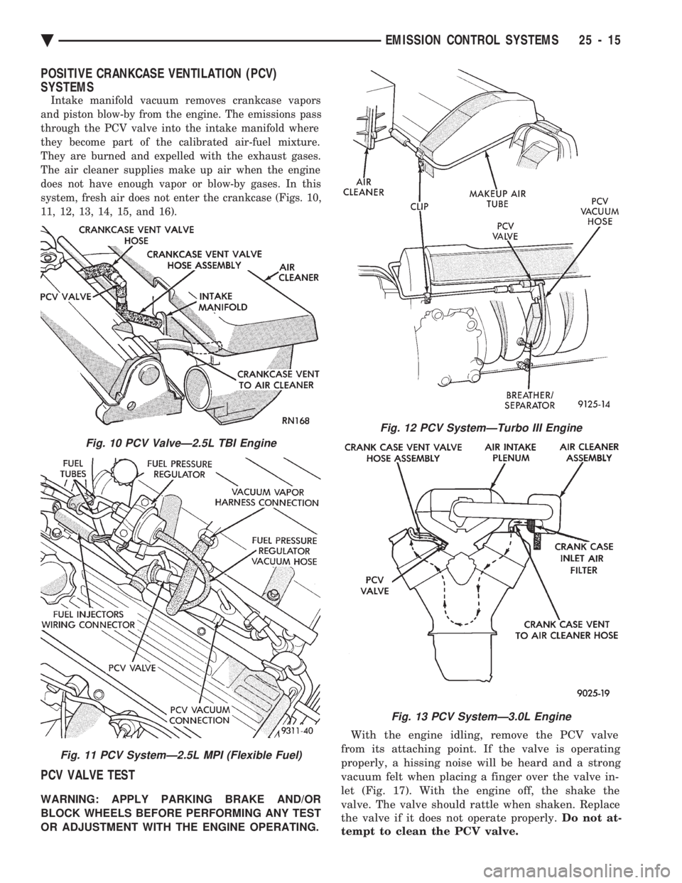
Intake manifold vacuum removes crankcase vapors
and piston blow-by from the engine. The emissions pass
through the PCV valve into the intake manifold where
they become part of the calibrated air-fuel mixture.
They are burned and expelled with the exhaust gases.
The air cleaner supplies make up air when the engine
does not have enough vapor or blow-by gases. In this
system, fresh air does not enter the crankcase (Figs. 10,
11, 12, 13, 14, 15, and 16).
PCV VALVE TEST
WARNING: APPLY PARKING BRAKE AND/OR
BLOCK WHEELS BEFORE PERFORMING ANY TEST
OR ADJUSTMENT WITH THE ENGINE OPERATING. With the engine idling, remove the PCV valve
from its attaching point. If the valve is operating
properly, a hissing noise will be heard and a strong
vacuum felt when placing a finger over the valve in-
let (Fig. 17). With the engine off, the shake the
valve. The valve should rattle when shaken. Replace
the valve if it does not operate properly. Do not at-
tempt to clean the PCV valve.
Fig. 10 PCV ValveÐ2.5L TBI Engine
Fig. 11 PCV SystemÐ2.5L MPI (Flexible Fuel)
Fig. 12 PCV SystemÐTurbo III Engine
Fig. 13 PCV SystemÐ3.0L Engine
Ä EMISSION CONTROL SYSTEMS 25 - 15
Page 2407 of 2438

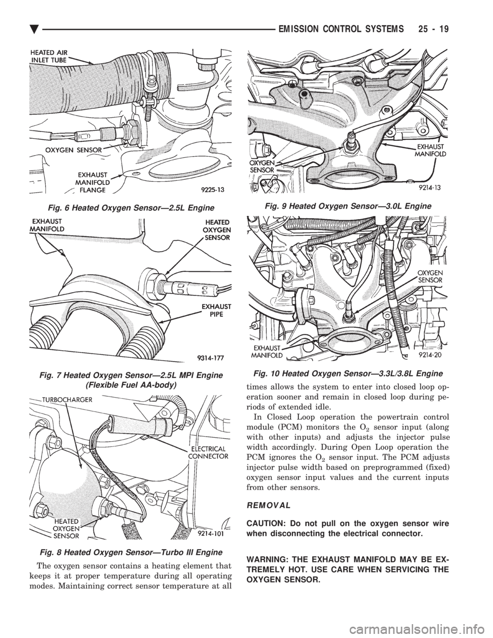
The oxygen sensor contains a heating element that
keeps it at proper temperature during all operating
modes. Maintaining correct sensor temperature at all times allows the system to enter into closed loop op-
eration sooner and remain in closed loop during pe-
riods of extended idle.
In Closed Loop operation the powertrain control
module (PCM) monitors the O
2sensor input (along
with other inputs) and adjusts the injector pulse
width accordingly. During Open Loop operation the
PCM ignores the O
2sensor input. The PCM adjusts
injector pulse width based on preprogrammed (fixed)
oxygen sensor input values and the current inputs
from other sensors.
REMOVAL
CAUTION: Do not pull on the oxygen sensor wire
when disconnecting the electrical connector.
WARNING: THE EXHAUST MANIFOLD MAY BE EX-
TREMELY HOT. USE CARE WHEN SERVICING THE
OXYGEN SENSOR.
Fig. 6 Heated Oxygen SensorÐ2.5L Engine
Fig. 7 Heated Oxygen SensorÐ2.5L MPI Engine (Flexible Fuel AA-body)
Fig. 8 Heated Oxygen SensorÐTurbo III Engine
Fig. 9 Heated Oxygen SensorÐ3.0L Engine
Fig. 10 Heated Oxygen SensorÐ3.3L/3.8L Engine
Ä EMISSION CONTROL SYSTEMS 25 - 19
Page 2409 of 2438

These systems do not allow EGR at idle. The 2.2L/
2.5L EGR systems operate at all temperatures. The
3.0L, 3.3L and 3.8L EGR systems do not operate
when coolant temperature is below 4.5ÉC (40É)F at
start-up. These systems activate when coolant tem-
perature reaches 77ÉC (170ÉF).
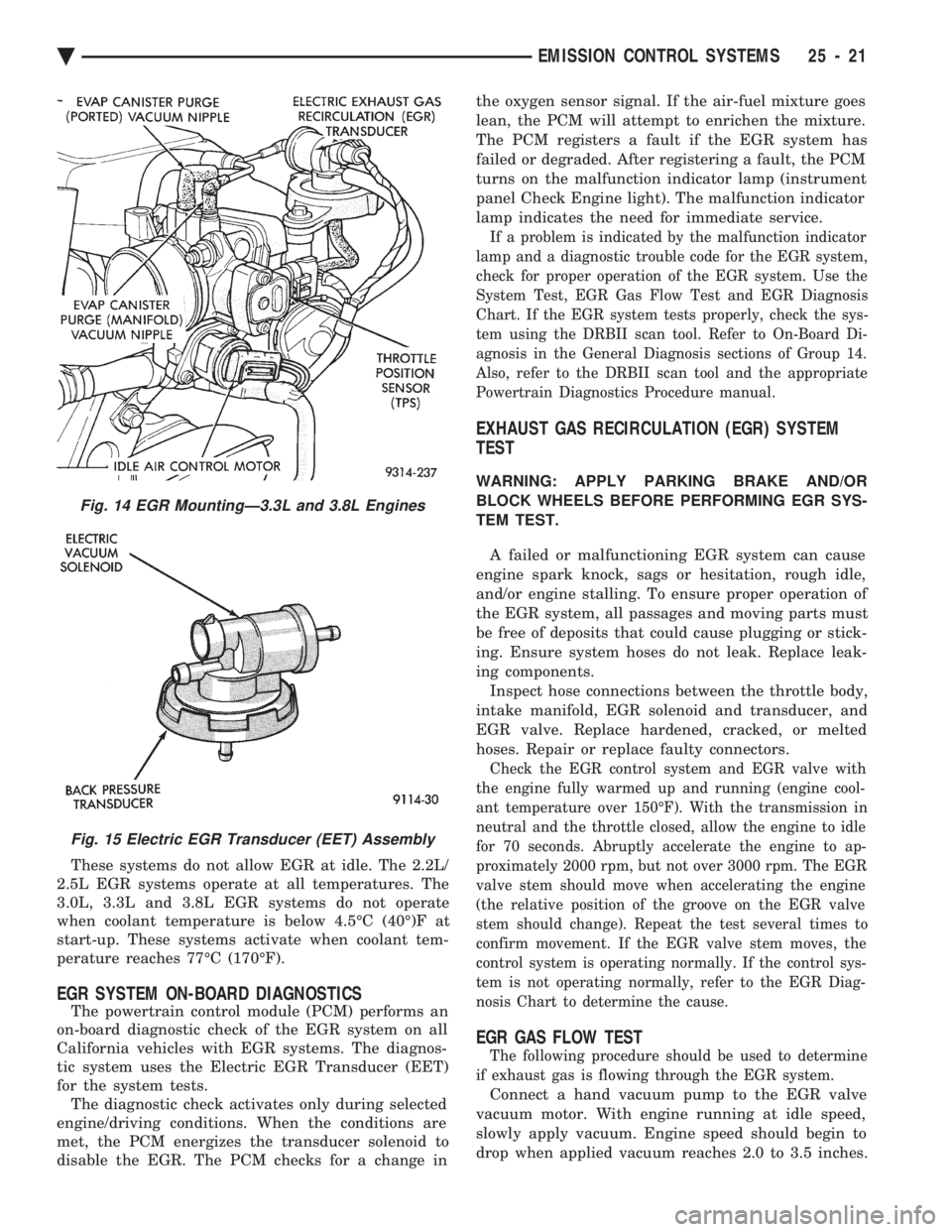
EGR SYSTEM ON-BOARD DIAGNOSTICS
The powertrain control module (PCM) performs an
on-board diagnostic check of the EGR system on all
California vehicles with EGR systems. The diagnos-
tic system uses the Electric EGR Transducer (EET)
for the system tests. The diagnostic check activates only during selected
engine/driving conditions. When the conditions are
met, the PCM energizes the transducer solenoid to
disable the EGR. The PCM checks for a change in the oxygen sensor signal. If the air-fuel mixture goes
lean, the PCM will attempt to enrichen the mixture.
The PCM registers a fault if the EGR system has
failed or degraded. After registering a fault, the PCM
turns on the malfunction indicator lamp (instrument
panel Check Engine light). The malfunction indicator
lamp indicates the need for immediate service.
If a problem is indicated by the malfunction indicator
lamp and a diagnostic trouble code for the EGR system,
check for proper operation of the EGR system. Use the
System Test, EGR Gas Flow Test and EGR Diagnosis
Chart. If the EGR system tests properly, check the sys-
tem using the DRBII scan tool. Refer to On-Board Di-
agnosis in the General Diagnosis sections of Group 14.
Also, refer to the DRBII scan tool and the appropriate
Powertrain Diagnostics Procedure manual.
EXHAUST GAS RECIRCULATION (EGR) SYSTEM
TEST
WARNING: APPLY PARKING BRAKE AND/OR
BLOCK WHEELS BEFORE PERFORMING EGR SYS-
TEM TEST.
A failed or malfunctioning EGR system can cause
engine spark knock, sags or hesitation, rough idle,
and/or engine stalling. To ensure proper operation of
the EGR system, all passages and moving parts must
be free of deposits that could cause plugging or stick-
ing. Ensure system hoses do not leak. Replace leak-
ing components. Inspect hose connections between the throttle body,
intake manifold, EGR solenoid and transducer, and
EGR valve. Replace hardened, cracked, or melted
hoses. Repair or replace faulty connectors.
Check the EGR control system and EGR valve with
the engine fully warmed up and running (engine cool-
ant temperature over 150ÉF). With the transmission in
neutral and the throttle closed, allow the engine to idle
for 70 seconds. Abruptly accelerate the engine to ap-
proximately 2000 rpm, but not over 3000 rpm. The EGR
valve stem should move when accelerating the engine
(the relative position of the groove on the EGR valve
stem should change). Repeat the test several times to
confirm movement. If the EGR valve stem moves, the
control system is operating normally. If the control sys-
tem is not operating normally, refer to the EGR Diag-
nosis Chart to determine the cause.
EGR GAS FLOW TEST
The following procedure should be used to determine
if exhaust gas is flowing through the EGR system.
Connect a hand vacuum pump to the EGR valve
vacuum motor. With engine running at idle speed,
slowly apply vacuum. Engine speed should begin to
drop when applied vacuum reaches 2.0 to 3.5 inches.
Fig. 14 EGR MountingÐ3.3L and 3.8L Engines
Fig. 15 Electric EGR Transducer (EET) Assembly
Ä EMISSION CONTROL SYSTEMS 25 - 21
Page 2422 of 2438
WARNING: USE OF AN INCORRECT FASTENER
MAY RESULT IN COMPONENT DAMAGE OR PER-
SONAL INJURY.
The metric system is based on quantities of one,
ten, one hundred, one thousand, and one million
(Fig. 8).
Fig. 8 Metric Prefixes
CONVERSION TABLES
Ä INTRODUCTION7
Page 2427 of 2438

CAUTION
ALL SERVICE AND REBUILDING INSTRUCTIONS CONTAINED HEREIN
ARE APPLICABLE TO, AND FOR THE CONVENIENCE OF, THE AUTOMOTIVE
TRADE ONLY. All test and repair procedures on components or assemblies in
non-automotive applications should be repaired in accordance with instructions
supplied by the manufacturer of the total product.
Proper service and repair is important to the safe, reliable, operation of all motor
vehicles. The service procedures recommended and described in this publication were
developed for professional service personnel and are effective methods for performing
vehicle repair. Following these procedures will help assure efficient economical vehicle
performance and service reliability. Some of these service procedures require the use
of special tools designed for specific procedures. These special tools should be used
when recommended throughout this publication.
Special attention should be exercised when working with spring or tension loaded
fasteners and devices such as E-Clips, Circlips, Snap rings, etc., as careless removal
may cause personal injury. Always wear safety goggles whenever working on vehicles
or vehicle components.
It is important to note that this publication contains various CautionsandWarnings.
These should be carefully read in order to minimize the risk of personal injury, or the
possibility that improper service methods may damage the vehicle or render it unsafe.
It is important to note that these CautionsandWarnings cover only the situations
and procedures DaimlerChrysler Corporation has encountered and recommended.
DaimlerChrysler Corporation could not possibly know, evaluate, and advise the
service trade of all conceivable ways that service may be performed, or of the possible
hazards of each. Consequently, DaimlerChrysler Corporation has not undertaken any
such broad service review. Accordingly, anyone who uses a service procedure, or tool,
that is not recommended in this publication must assure oneself thoroughly that
neither personal safety, nor vehicle safety, be jeopardized by the service methods they
select.
SERVICE AND OWNER MANUALS
Available for Chrysler, Plymouth, Dodge, Dodge Truck, and Jeep
Tvehicles.
Telephone orders may be placed at the number below.
Credit cards are accepted (no CODs). Please have your
order information available at time of call.
CALL: (800) 890-4038 OR FAX: (440) 572-0815
FOR A FREE CATALOG OR TO PLACE AN ORDER.
NEXT PAGE ©
llllllllllll