1993 CHEVROLET DYNASTY warning
[x] Cancel search: warningPage 1820 of 2438
(3) Ensure the injector holes are clean and all plugs
have been removed. (4) Lubricate the injector O-rings with a drop of
clean engine oil to ease installation. (5) Install the injector assembly into their holes.
Install mounting screws. Fuel rail assembly must be
drawn into the intake manifold evenly making sure
each injector enters its own hole. Once all injectors are
seated, tighten bolts to 23 N Im (200 in. lbs) torque.
(6) Connect vacuum hose to fuel pressure regulator.
(7) Close fuel tube clip around fuel tubes and install
fastener. (8) Lubricate the ends of the chassis fuel tubes with
a light coating of clean 30 weight engine oil. Connect
fuel supply and return hoses to chassis fuel tube
assembly. Pull back on the quick connect fittings to
ensure complete insertion. Refer to Quick Connect
Fittings in the Fuel Delivery section of this group. (9) Connect vacuum hose intake manifold nipple.
(10) Connect negative cable to battery.
CAUTION: When using the ASD Fuel System Test, the
Auto Shutdown (ASD) Relay remains energized for
either 7 minutes, until the test is stopped, or until the
ignition switch is turned to the Off position.
(11) With the DRBII scan tool, use the ASD Fuel
System Test to pressurize system and check for leaks.
FUEL INJECTOR
The fuel rail must be removed to service the injec-
tors. Refer to Fuel Injector Rail Assembly in this
section.
REMOVAL
WARNING: RELEASE FUEL SYSTEM PRESSURE BE-
FORE SERVICING FUEL SYSTEM COMPONENTS.
WHEN SERVICING FLEXIBLE FUEL VEHICLES,
WEAR METHANOL RESISTANT GLOVES AND EYE
PROTECTION AND AVOID BREATHING FUMES. DO NOT ALLOW METHANOL/GASOLINE MIXTURES TO
CONTACT SKIN. SERVICE VEHICLES IN WELL VEN-
TILATED AREAS AND AVOID IGNITION SOURCES.
NEVER SMOKE WHILE SERVICING THE VEHICLE.
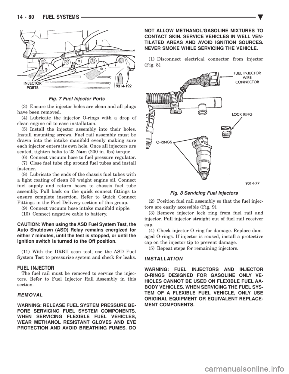
(1) Disconnect electrical connector from injector
(Fig. 8).
(2) Position fuel rail assembly so that the fuel injec-
tors are easily accessible (Fig. 9). (3) Remove injector lock ring from fuel rail and
injector. Pull injector straight out of fuel rail receiver
cup. (4) Check injector O-ring for damage. Replace dam-
aged O-rings. If injector is reused, install a protective
cap on the injector tip to prevent damage. (5) Repeat steps for remaining injectors.
INSTALLATION
WARNING: FUEL INJECTORS AND INJECTOR
O-RINGS DESIGNED FOR GASOLINE ONLY VE-
HICLES CANNOT BE USED ON FLEXIBLE FUEL AA-
BODY VEHICLES. WHEN SERVICING THE FUEL SYS-
TEM OF A FLEXIBLE FUEL VEHICLE, ONLY USE
ORIGINAL EQUIPMENT OR EQUIVALENT REPLACE-
MENT COMPONENTS.
Fig. 7 Fuel Injector Ports
Fig. 8 Servicing Fuel Injectors
14 - 80 FUEL SYSTEMS Ä
Page 1821 of 2438
(1) Before installing an injector, lubricate O-ring
with a drop of clean engine oil. (2) Being careful not to damage the O-ring, install
injector top end into fuel rail receiver cup. (3) Install injector lock ring by sliding open end
into slot of the injector and onto the receiver cup
ridge into the side slots of ring (Fig. 8). (4) Repeat steps for remaining injectors.
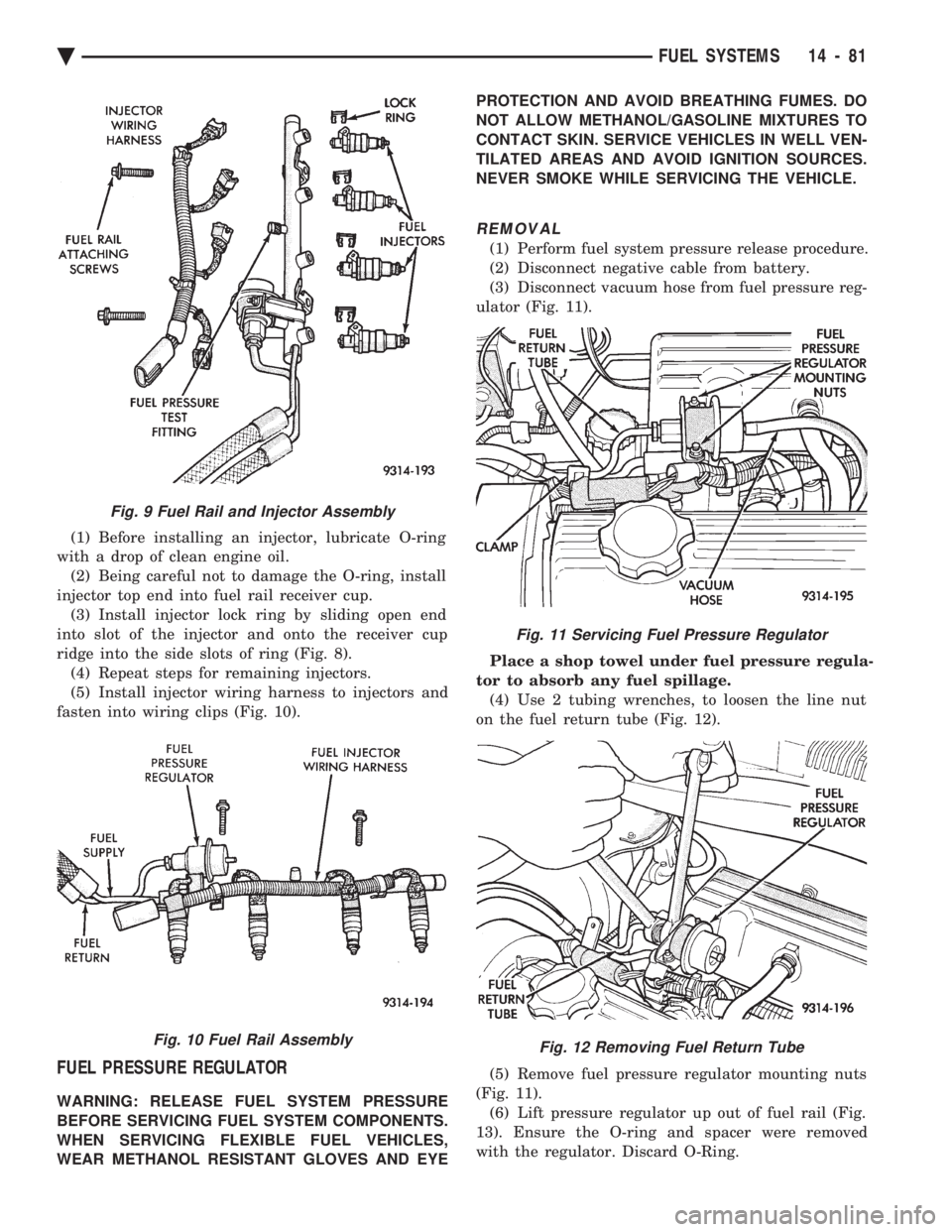
(5) Install injector wiring harness to injectors and
fasten into wiring clips (Fig. 10).
FUEL PRESSURE REGULATOR
WARNING: RELEASE FUEL SYSTEM PRESSURE
BEFORE SERVICING FUEL SYSTEM COMPONENTS.
WHEN SERVICING FLEXIBLE FUEL VEHICLES,
WEAR METHANOL RESISTANT GLOVES AND EYE PROTECTION AND AVOID BREATHING FUMES. DO
NOT ALLOW METHANOL/GASOLINE MIXTURES TO
CONTACT SKIN. SERVICE VEHICLES IN WELL VEN-
TILATED AREAS AND AVOID IGNITION SOURCES.
NEVER SMOKE WHILE SERVICING THE VEHICLE.
REMOVAL
(1) Perform fuel system pressure release procedure.
(2) Disconnect negative cable from battery.
(3) Disconnect vacuum hose from fuel pressure reg-
ulator (Fig. 11).
Place a shop towel under fuel pressure regula-
tor to absorb any fuel spillage. (4) Use 2 tubing wrenches, to loosen the line nut
on the fuel return tube (Fig. 12).
(5) Remove fuel pressure regulator mounting nuts
(Fig. 11). (6) Lift pressure regulator up out of fuel rail (Fig.
13). Ensure the O-ring and spacer were removed
with the regulator. Discard O-Ring.
Fig. 9 Fuel Rail and Injector Assembly
Fig. 10 Fuel Rail Assembly
Fig. 11 Servicing Fuel Pressure Regulator
Fig. 12 Removing Fuel Return Tube
Ä FUEL SYSTEMS 14 - 81
Page 1822 of 2438
INSTALLATION
WARNING: THE FUEL PRESSURE REGULATOR,
O-RING AND SPACER DESIGNED FOR GASOLINE
ONLY VEHICLES CANNOT BE USED ON FLEXIBLE
FUEL AA-BODY VEHICLES. WHEN SERVICING THE
FUEL SYSTEM OF A FLEXIBLE FUEL VEHICLE,
ONLY USE ORIGINAL EQUIPMENT OR EQUIVA-
LENT REPLACEMENT COMPONENTS.
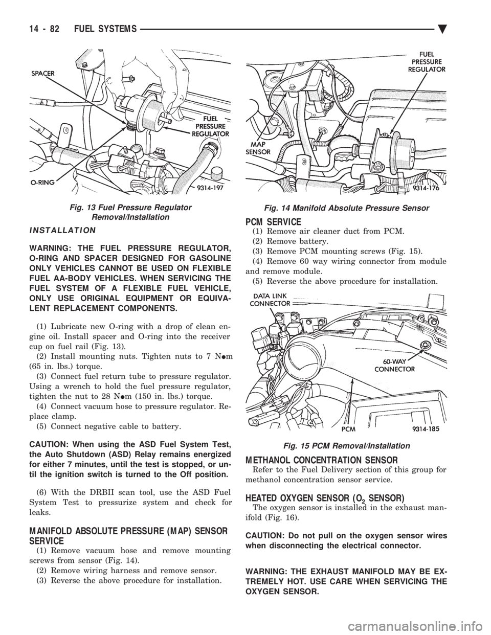
(1) Lubricate new O-ring with a drop of clean en-
gine oil. Install spacer and O-ring into the receiver
cup on fuel rail (Fig. 13). (2) Install mounting nuts. Tighten nuts to 7 N Im
(65 in. lbs.) torque. (3) Connect fuel return tube to pressure regulator.
Using a wrench to hold the fuel pressure regulator,
tighten the nut to 28 N Im (150 in. lbs.) torque.
(4) Connect vacuum hose to pressure regulator. Re-
place clamp. (5) Connect negative cable to battery.
CAUTION: When using the ASD Fuel System Test,
the Auto Shutdown (ASD) Relay remains energized
for either 7 minutes, until the test is stopped, or un-
til the ignition switch is turned to the Off position.
(6) With the DRBII scan tool, use the ASD Fuel
System Test to pressurize system and check for
leaks.
MANIFOLD ABSOLUTE PRESSURE (MAP) SENSOR
SERVICE
(1) Remove vacuum hose and remove mounting
screws from sensor (Fig. 14). (2) Remove wiring harness and remove sensor.
(3) Reverse the above procedure for installation.
PCM SERVICE
(1) Remove air cleaner duct from PCM.
(2) Remove battery.
(3) Remove PCM mounting screws (Fig. 15).
(4) Remove 60 way wiring connector from module
and remove module. (5) Reverse the above procedure for installation.
METHANOL CONCENTRATION SENSOR
Refer to the Fuel Delivery section of this group for
methanol concentration sensor service.
HEATED OXYGEN SENSOR (O2SENSOR)
The oxygen sensor is installed in the exhaust man-
ifold (Fig. 16).
CAUTION: Do not pull on the oxygen sensor wires
when disconnecting the electrical connector.
WARNING: THE EXHAUST MANIFOLD MAY BE EX-
TREMELY HOT. USE CARE WHEN SERVICING THE
OXYGEN SENSOR.
Fig. 13 Fuel Pressure Regulator Removal/InstallationFig. 14 Manifold Absolute Pressure Sensor
Fig. 15 PCM Removal/Installation
14 - 82 FUEL SYSTEMS Ä
Page 1849 of 2438
FUEL INJECTOR RAIL ASSEMBLY
WARNING: THE 2.2L TURBO III FUEL SYSTEM IS
UNDER A CONSTANT PRESSURE OF APPROXI-
MATELY 380 KPA (55 PSI). PERFORM FUEL PRES-
SURE RELEASE PROCEDURE BEFORE SERVICING
THE FUEL RAIL OR FUEL INJECTORS.
REMOVAL
(1) Perform fuel system pressure release procedure.
(2) Disconnect negative battery cable.
CAUTION: Place a shop towel should under the fuel
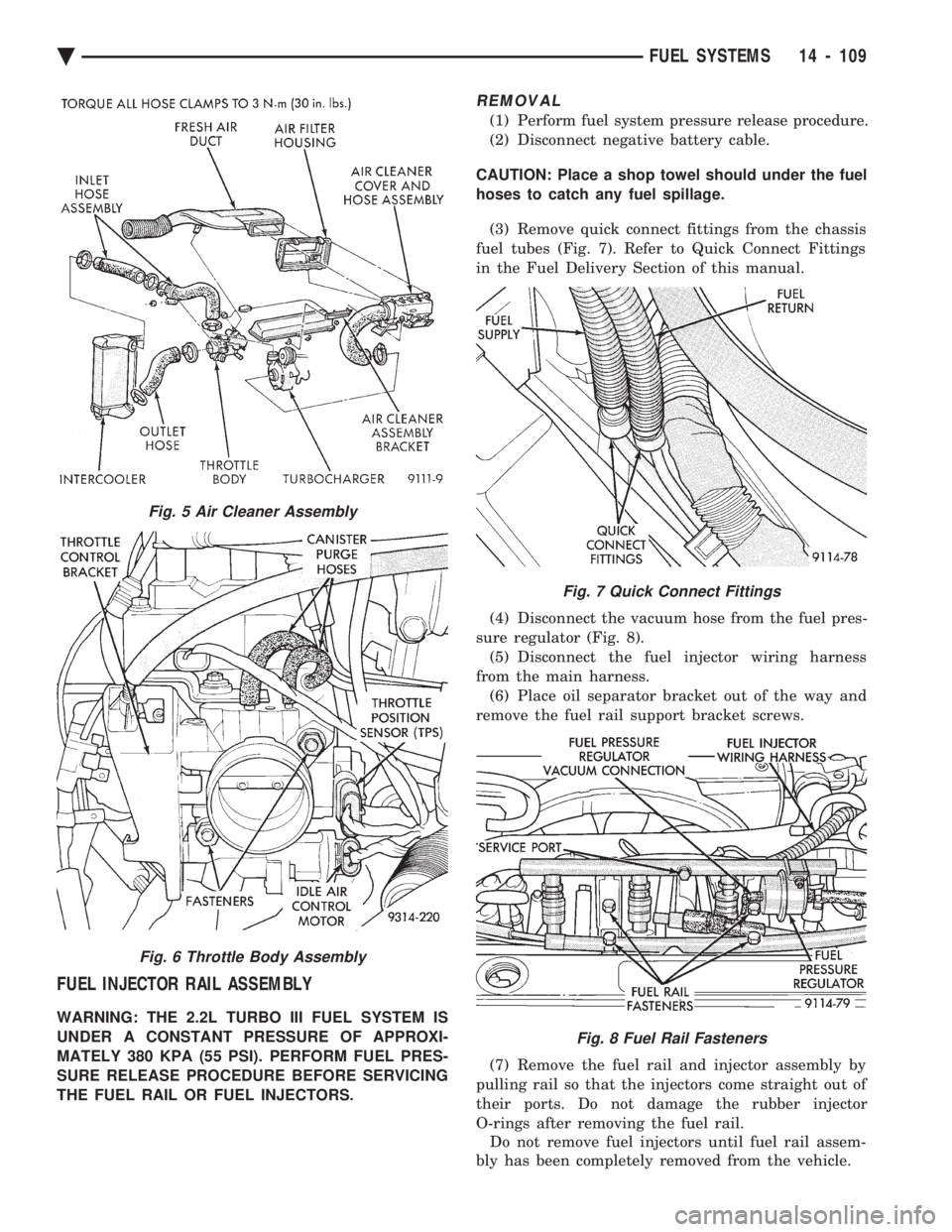
hoses to catch any fuel spillage. (3) Remove quick connect fittings from the chassis
fuel tubes (Fig. 7). Refer to Quick Connect Fittings
in the Fuel Delivery Section of this manual.
(4) Disconnect the vacuum hose from the fuel pres-
sure regulator (Fig. 8). (5) Disconnect the fuel injector wiring harness
from the main harness. (6) Place oil separator bracket out of the way and
remove the fuel rail support bracket screws.
(7) Remove the fuel rail and injector assembly by
pulling rail so that the injectors come straight out of
their ports. Do not damage the rubber injector
O-rings after removing the fuel rail. Do not remove fuel injectors until fuel rail assem-
bly has been completely removed from the vehicle.
Fig. 7 Quick Connect Fittings
Fig. 8 Fuel Rail Fasteners
Fig. 5 Air Cleaner Assembly
Fig. 6 Throttle Body Assembly
Ä FUEL SYSTEMS 14 - 109
Page 1851 of 2438
INSTALLATION
(1) Before installing an injector, the rubber O-ring
must be lubricated with a drop of clean engine oil to aid
in installation. (2) Being careful not to damage the O-ring, install
injector top end into fuel rail receiver cup. (3) Install injector lock ring by sliding open end into
slot of the injector and onto the receiver cup ridge into
the side slots of ring (Fig. 11). (4) Repeat steps for remaining injectors.
(5) Install injector wiring harness to injectors. Place
harness into retaining clips.
FUEL PRESSURE REGULATOR
WARNING: THE 2.2L TURBO III FUEL SYSTEM IS
UNDER A CONSTANT PRESSURE OF APPROXI-
MATELY 380 KPA (55 PSI). PERFORM FUEL PRES-
SURE RELEASE PROCEDURE BEFORE SERVICING
THE FUEL PRESSURE REGULATOR.
REMOVAL
(1) Perform fuel system pressure release procedure.
(2) Disconnect negative cable from battery.
(3) Disconnect vacuum hose from fuel pressure regu-
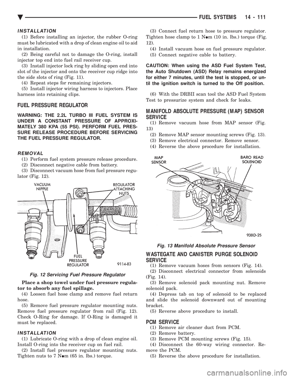
lator (Fig. 12).
Place a shop towel under fuel pressure regula-
tor to absorb any fuel spillage. (4) Loosen fuel hose clamp and remove fuel return
hose. (5) Remove fuel pressure regulator mounting nuts.
Remove fuel pressure regulator from rail (Fig. 12).
Check O-Ring for damage. If O-Ring is damaged it
must be replaced.
INSTALLATION
(1) Lubricate O-ring with a drop of clean engine oil.
Install O-ring into the receiver cup on fuel rail. (2) Install fuel pressure regulator mounting nuts.
Tighten nuts to 7 N Im (65 in. lbs.) torque. (3) Connect fuel return hose to pressure regulator.
Tighten hose clamp to 1 N Im (10 in. lbs.) torque (Fig.
12). (4) Install vacuum hose on fuel pressure regulator.
(5) Connect negative cable to battery.
CAUTION: When using the ASD Fuel System Test,
the Auto Shutdown (ASD) Relay remains energized
for either 7 minutes, until the test is stopped, or un-
til the ignition switch is turned to the Off position. (6) With the DRBII scan tool the ASD Fuel System
Test to pressurize system and check for leaks.
MANIFOLD ABSOLUTE PRESSURE (MAP) SENSOR
SERVICE
(1) Remove vacuum hose from MAP sensor (Fig.
13) (2) Remove MAP sensor mounting screws (Fig. 13).
(3) Remove electrical connector. Remove sensor.
(4) Reverse the above procedure for installation.
WASTEGATE AND CANISTER PURGE SOLENOID
SERVICE
(1) Remove vacuum hoses from sensors (Fig. 14).
(2) Disconnect electrical connector from solenoids
(Fig. 14). (3) Remove solenoid pack mounting nut. Remove
solenoid pack. (4) Depress tab on top of solenoid to be replaced
and slide the solenoid downward out of mounting
bracket. (5) Reverse above procedure to install.
PCM SERVICE
(1) Remove air cleaner duct from PCM.
(2) Remove battery.
(3) Remove PCM mounting screws (Fig. 15).
(4) Disconnect the 60-way wiring connector. Re-
move the PCM. (5) Reverse the above procedure for installation.
Fig. 13 Manifold Absolute Pressure Sensor
Fig. 12 Servicing Fuel Pressure Regulator
Ä FUEL SYSTEMS 14 - 111
Page 1852 of 2438
HEATED OXYGEN SENSOR (O2SENSOR)
The oxygen sensor is installed in the exhaust man-
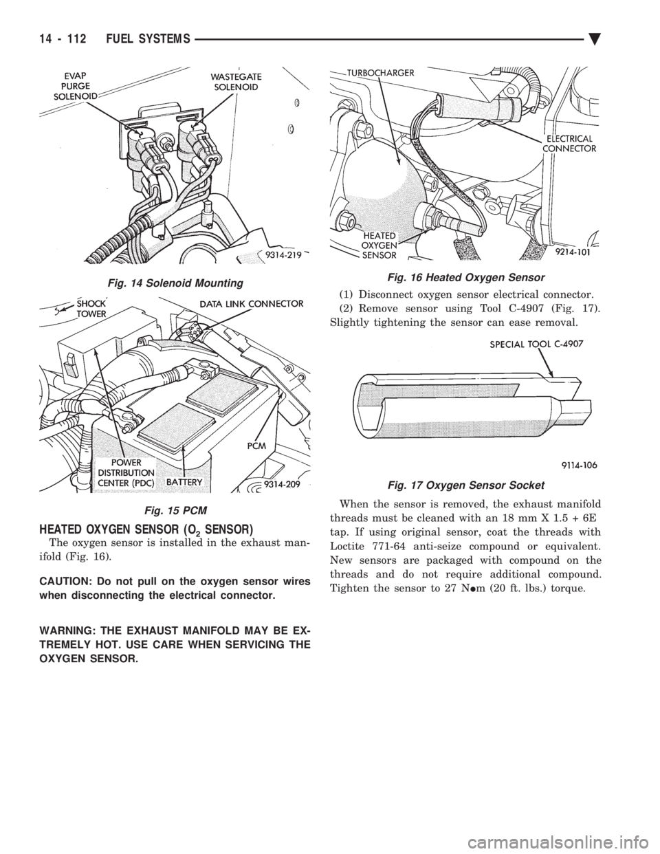
ifold (Fig. 16).
CAUTION: Do not pull on the oxygen sensor wires
when disconnecting the electrical connector.
WARNING: THE EXHAUST MANIFOLD MAY BE EX-
TREMELY HOT. USE CARE WHEN SERVICING THE
OXYGEN SENSOR. (1) Disconnect oxygen sensor electrical connector.
(2) Remove sensor using Tool C-4907 (Fig. 17).
Slightly tightening the sensor can ease removal.
When the sensor is removed, the exhaust manifold
threads must be cleaned with an 18 mm X 1.5 + 6E
tap. If using original sensor, coat the threads with
Loctite 771-64 anti-seize compound or equivalent.
New sensors are packaged with compound on the
threads and do not require additional compound.
Tighten the sensor to 27 N Im (20 ft. lbs.) torque.
Fig. 14 Solenoid Mounting
Fig. 15 PCM
Fig. 16 Heated Oxygen Sensor
Fig. 17 Oxygen Sensor Socket
14 - 112 FUEL SYSTEMS Ä
Page 1874 of 2438
SYSTEM TESTS
WARNING: APPLY PARKING BRAKE AND/OR BLOCK
WHEELS BEFORE PERFORMING ANY TEST ON AN
OPERATING ENGINE.
OBTAINING DIAGNOSTIC TROUBLE CODES
(1) Connect DRBII scan tool to the data link connec-
tor located in the engine compartment near the pow-
ertrain control module (PCM). (2) Start the engine if possible, cycle the transaxle
selector and the A/Cswitch if applicable. Shut off the
engine. (3) Turn the ignition switch on, access Read Fault
Screen. Record all the fault messages shown on the
DRBII scan tool. Observe the malfunction indicator
lamp (Check Engine lamp on the instrument panel).
The lamp should light for 3 seconds then go out (bulb
check). Diagnostic trouble code erasure; access erase
diagnostic trouble code data
STATE DISPLAY TEST MODE
The switch inputs used by the powertrain control
module (PCM) have only two recognized states, HIGH
and LOW. For this reason, the PCM cannot recognize
the difference between a selected switch position ver-
sus an open circuit, a short circuit, or a defective
switch. If the change is displayed, it can be assumed
that the entire switch circuit to the PCM is functional.
From the state display screen access either State
Display Inputs and Outputs or State Display Sensors.
STATE DISPLAY INPUTS AND OUTPUTS
Connect the DRBII scan tool to the vehicle. Access
the State Display screen. Then access Inputs and
Outputs. The following is a list of the engine control
system functions accessible through the Inputs and
Outputs screen. Park/Neutral Switch
Speed Control Resume
Brake Switch
Speed Control On/Off
Speed Control Set
A/C Switch Sense
S/C Vent Solenoid
S/C Vacuum Solenoid
A/C Clutch Relay
EGR Solenoid
Auto Shutdown Relay
Radiator Fan Relay
Purge Solenoid
Torque Converter Clutch Solenoid
Malfunction Indicator Lamp (Check Engine Lamp)
STATE DISPLAY SENSORS
Connect the DRBII scan tool to the vehicle and ac-
cess the State Display screen. Then access Sensor
Display. The following is a list of the engine control
system functions accessible through the Sensor Dis-
play screen. Battery Temperature
Oxygen Sensor Signal
Engine Coolant Temperature
Engine Coolant Temp Sensor
Throttle Position
Minimum Throttle
Battery Voltage
MAP Sensor Reading
Idle Air Control Motor Position
Adaptive Fuel Factor
Barometric Pressure
Min Airflow Idle Speed
Engine Speed
Fault #1 Key-On Info
Module Spark Advance
Speed Control Target
Fault #2 Key-on Info
Fault #3 Key-on Info
Speed Control Status
Speed Control Switch Voltage
Charging System Goal
Theft Alarm Status
Map Sensor Voltage
Vehicle Speed
Oxygen Sensor State
MAP Gauge Reading
Throttle Opening (percentage)
Total Spark Advance
CIRCUIT ACTUATION TEST MODE
The circuit actuation test mode checks for proper
operation of output circuits or devices which the pow-
ertrain control module (PCM) cannot internally rec-
ognize. The PCM can attempt to activate these
outputs and allow an observer to verify proper oper-
ation. Most of the tests provide an audible or visual
indication of device operation (click of relay contacts,
spray fuel, etc.). Except for intermittent conditions, if
a device functions properly during testing, assume
the device, its associated wiring, and driver circuit
working correctly.
OBTAINING CIRCUIT ACTUATION TEST
Connect the DRBII scan tool to the vehicle and ac-
cess the Actuators screen. The following is a list of
the engine control system functions accessible
through Actuators screens. Stop All Tests
Ignition Coil #1
Fuel Injector #1
Fuel Injector #2
Fuel Injector #3
14 - 134 FUEL SYSTEMS Ä
Page 1876 of 2438
WARNING: CLEAN THROTTLE BODY IN A WELL
VENTILATED AREA. WEAR RUBBER OF BUTYL
GLOVES, DO NOT LET MOPAR PARTS CLEANER
COME IN CONTACT WITH EYES OR SKIN. AVOID
INGESTING THE CLEANER. WASH THOROUGHLY
AFTER USING CLEANER.
(b) While holding the throttle open, spray the
entire throttle body bore and the manifold side of the
throttle plate with Mopar Parts Cleaner. Only use
Mopar Parts Cleaner to clean the throttle body. (c) Using a soft scuff pad, clean the top and bottom
of throttle body bore and the edges and manifold side
of the throttle blade. The edges of the throttle
blade and portions of the throttle bore that are
closest to the throttle blade when is closed,
must be free of deposits. (d) Use compressed air to dry the throttle body.
(e) Inspect throttle body for foreign material. (f) Install throttle body on manifold.
(g) Repeat steps 1 through 14. If the minimum air
flow is still not within specifications, the problem is
not caused by the throttle body.
(16) Shut off engine.
(17) Remove Air Metering Fitting #6457 from the
intake manifold idle purge hose. Reconnect the hose to
the engine vacuum harness tee. (18) Remove the plug from the PCV valve. Reconnect
the PCV valve hose to the PCV valve. (19) Disconnect the DRBII scan tool.
IGNITION TIMING PROCEDURE
Refer to Group 8D Ignition System.
60-WAY PCM WIRING CONNECTOR
Refer to the PCM wiring connector description (Fig.
7) for information regarding wire colors and cavity
numbers.
14 - 136 FUEL SYSTEMS Ä