Page 1046 of 1216

23-2
SPECIFICATIONS
GENERAL SPECIFICATIONS
BODY - Specifications
N23CA--
Items
Hood
We
Door
Construction
Regulator system
Locking system
Liftgate
We
Slass installation method
Windshield glass
Quarter window glass
Liftgate window glass
Zlass thicknessmm (in.)
Windshield glass
Liftgate window glass
Door glass
Quarter window glass
‘ower window motor
Type
Revolutions under no loadwm
Revolutions under load
wmAt 1
Nm t.72 ft.lbs.1At 2
Nm (1.45 ft.lbs.1Bound current A
Direction of rotation
‘ower window main switch
Type
Rated load currentA
Lock switch
Power window switch
‘ower window sub switch
TvwRated load current A
‘ower window relay
Maximum contact currentA
Rated coil currentA
Voltage drop between terminalsV(At 12 V and the rated load current)
Specifications
Rear hinged, front opening type
Front-hinged, sash construction
Wire type
Pin-fork type
Inner-hinged, with gas damper
Adhesive type
Adhesive type
Adhesive type5.3
i.21)3.5
t.1413.5
t.1413.5
t.141
Permanent magnet type (Built-in circuit breaker)
75 or more65-95
50-80
34 or less
Clockwise and counter-clockwise
Automatic reset type
10
10
Automatic reset type
10
20
Max. 0.2
0.2 or less
Page 1047 of 1216

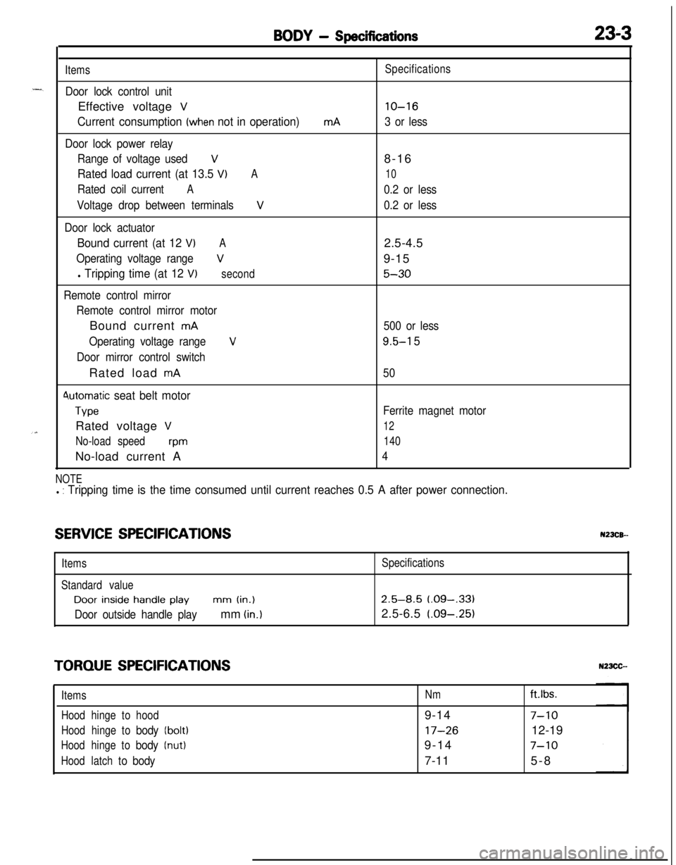
BODY - Specifications23-3
Items
Door lock control unitEffective voltage
V
Current consumption (when not in operation)
Door lock power relay
Range of voltage used
V
Rated load current (at 13.5 VIA
Rated coil currentA
Voltage drop between terminalsV
Door lock actuator
Bound current (at 12 VIA
Operating voltage rangeV
l Tripping time (at 12 V)second
Remote control mirror
Remote control mirror motorBound current
mA
Operating voltage range
V
Door mirror control switchRated load
mA
4utomatic seat belt motor
TypeRated voltage
V
No-load speedwmNo-load current A
mASpecifications
lo-16
3 or less8-16
10
0.2 or less
0.2 or less2.5-4.5
9-15
5-30
500 or less
9.5-l 5
50
Ferrite magnet motor
12
140
4
NOTEl : Tripping time is the time consumed until current reaches 0.5 A after power connection.
SERVICE SPECIFICATIONSN23CB--
ItemsSpecifications
Standard valueDoor
inside handle playmm (in.)2.5-8.5 (.09-,331
Door outside handle playmm (in.)2.5-6.5 (.09-.25)
TORQUE SPECIFICATIONS
ItemsNmft.lbs.
Hoodhingetohood9-14
7-10
Hoodhingetobody(bolt)17-2612-19
Hoodhingetobody(nut)9-147-10
Hoodlatchtobody7-115-8
Page 1054 of 1216

23-10BODY - Troubleshooting
(PABBENGER’B BIDE)v 1
E-51
‘S
E-05
I2
m3458
POWER WINDOW
MOTOR
E-04
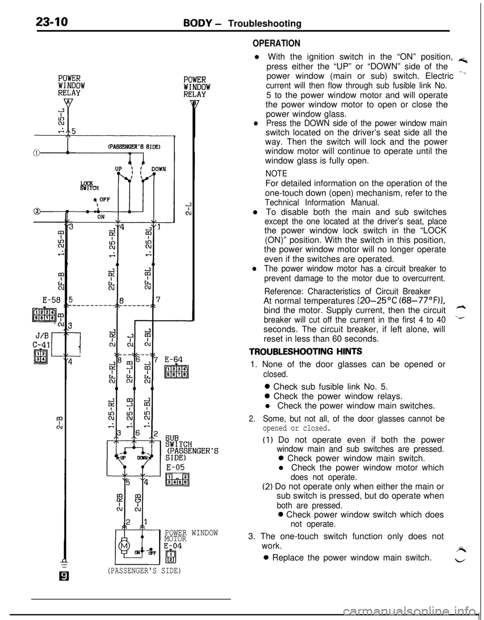
OPERATIONl With the ignition switch in the “ON” position,
rs;,press either the “UP” or “DOWN” side of the
power window (main or sub) switch. Electric
-*
current will then flow through sub fusible link No.5 to the power window motor and will operate
the power window motor to open or close the
power window glass.
lPress the DOWN side of the power window mainswitch located on the driver’s seat side all the
way. Then the switch will lock and the power
window motor will continue to operate until the
window glass is fully open.
NOTEFor detailed information on the operation of the
one-touch down (open) mechanism, refer to the
Technical Information Manual.l To disable both the main and sub switches
except the one located at the driver’s seat, placethe power window lock switch in the “LOCK
(ON)” position. With the switch in this position,
the power window motor will no longer operate
even if the switches are operated.
lThe power window motor has a circuit breaker to
prevent damage to the motor due to overcurrent.
Reference: Characteristics of Circuit BreakerAt normal temperatures
[ZO-25OC (68-77”F)I,bind the motor. Supply current, then the circuit
h
breaker will cut off the current in the first 4 to 40\&’seconds. The circuit breaker, if left alone, will
reset in less than 60 seconds.
TROUBLESHOOTING HINTS1. None of the door glasses can be opened or
closed.0 Check sub fusible link No. 5.0 Check the power window relays.
l Check the power window main switches.
2.Some, but not all, of the door glasses cannot be
opened or closed.
(I) Do not operate even if both the power
window main and sub switches are pressed.0 Check power window main switch.
l Check the power window motor which
does not operate.
(2) Do not operate only when either the main or
sub switch is pressed, but do operate when
both are pressed.0 Check power window switch which does
not operate.3. The one-touch switch function only does not
work.A0 Replace the power window main switch.
w
(PASSENGER'S SIDE)
Page 1057 of 1216

BODY - Troubleshooting23-13
OPERATION
TROUBLESHOOTING HINTS
-.l If the inside lock knobs of the doors are placedin the LOCK (or UNLOCK) position, the switch inthe door lock actuator will be “OFF” (or “ON”),
and the output transistor will be “ON” for 0.5
second according to the timer function in the
door lock control unit (or theft-alarm control unit).As a result, the LOCK side (or UNLOCK side) of
the door lock relay will be “ON”, operating the
actuators of all of the doors.
NOTE
The door lock actuator contains a PTC thermistor
to prevent damage caused by overheating of the
motor. If the central door lock is frequently used,the actuator may temporarily fail to operate. If it
returns to normal in a few minutes, it is not
defective.
1.
2.One of the door lock actuators fails to operate.
l Check the door actuator which fails to
operate.Cannot be placed in the LOCK or UNLOCK
position by the inside lock knob on either driver’s
or front passenger’s seat side.0 Check the switch in the actuator.0 Check the door lock control unit (or
theft-alarm control unit).
DOOR LOCK CONTROL UNIT (OR THEFT-ALARM CONTROL UNIT) TERMINAL VOLTAGE (Connector
Connected)
TerminalSignal nameConditionTerminalNo.voltage1 or
5”’Door lock relayThe moment the inside lock knob is0.5 vs2
activation signal
pressed down (approx. 0.5 sec.)
NormallySystem voltage2 or 19”’
(Driver’s seat side) insideWhen the inside lock knob is placedSystem voltage
door lock knob signalin the “LOCK” position
When the inside lock knob is placedov
in the “UNLOCK” position3 or
4”’Door lock relayThe moment the inside lock knob is0.5 v2
activation signalpulled up (approx. 0.5 sec.)
NormallySystem voltage4 or 20”’
(Passenger’s seat side)When the inside lock knob is placedSystem voltage
inside door lock knob signalin the “LOCK” position
When the inside lock knob is placedovin the “UNLOCK” position5 or
12*’Power supplyAlwaysSystem voltage6 or
7(11)*’GroundAlwaysov
NOTE*I: Vehicles with theft-alarm system.
*2:Because of the internal resistance of the output transistor, the normal terminal voltage is 0.5 V. If it is 0 V, an open orshort circuit in the harness is suspected.
Page 1063 of 1216

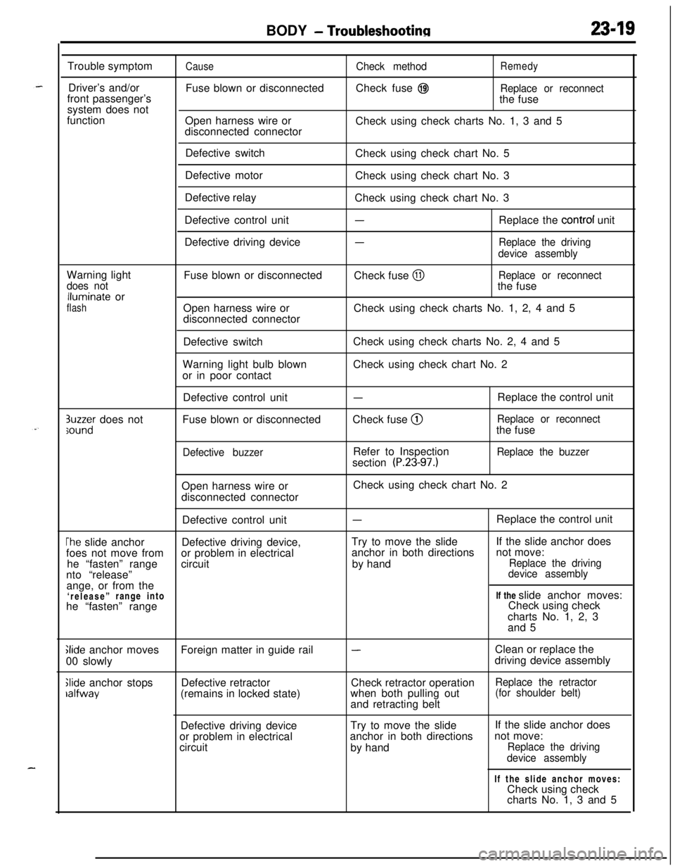
BODY - Troubleshootinn2349Trouble symptom
Driver’s and/or
front passenger’s
system does not
function
CauseFuse blown or disconnected
Open harness wire or
disconnected connectorCheck methodRemedyCheck fuse
@IReplace or reconnectthe fuse
Check using check charts No. 1, 3 and 5
Defective switch
Defective motor
Defective relay
Defective control unit
Defective driving deviceCheck using check chart No. 5
Check using check chart No. 3
Check using check chart No. 3
-Replace the control unit
-Replace the driving
device assemblyWarning light
does notlluminate or
flashFuse blown or disconnected
Open harness wire or
disconnected connectorCheck fuse
@IReplace or reconnectthe fuse
Check using check charts No. 1, 2, 4 and 5
Defective switch
Warning light bulb blown
or in poor contactCheck using check charts No. 2, 4 and 5
Check using check chart No. 2
3uzzer does notsoundDefective control unit
Fuse blown or disconnected
Defective buzzer
-Check fuse @
Refer to Inspection
section
(P.23-97.)Replace the control unit
Replace or reconnectthe fuse
Replace the buzzerOpen harness wire or
disconnected connectorCheck using check chart No. 2
Defective control unit
-Replace the control unit
The slide anchorDefective driving device,Try to move the slideIf the slide anchor does
foes not move fromor problem in electricalanchor in both directionsnot move:
he “fasten” rangecircuitby hand
Replace the drivingnto “release”device assemblyange, or from the
‘release”range intoIf the slide anchor moves:
he “fasten” rangeCheck using check
charts No. 1, 2, 3
and 5
Glide anchor moves
00 slowly
Slide anchor stopsralfwayForeign matter in guide rail
Defective retractor
(remains in locked state)
-Clean or replace the
driving device assembly
Check retractor operation
Replace the retractorwhen both pulling out(for shoulder belt)and retracting belt
Defective driving deviceTry to move the slide
or problem in electricalanchor in both directions
circuit
by handIf the slide anchor does
not move:
Replace the driving
device assemblyIf the slide anchor moves:
Check using check
charts No. 1, 3 and 5
Page 1072 of 1216

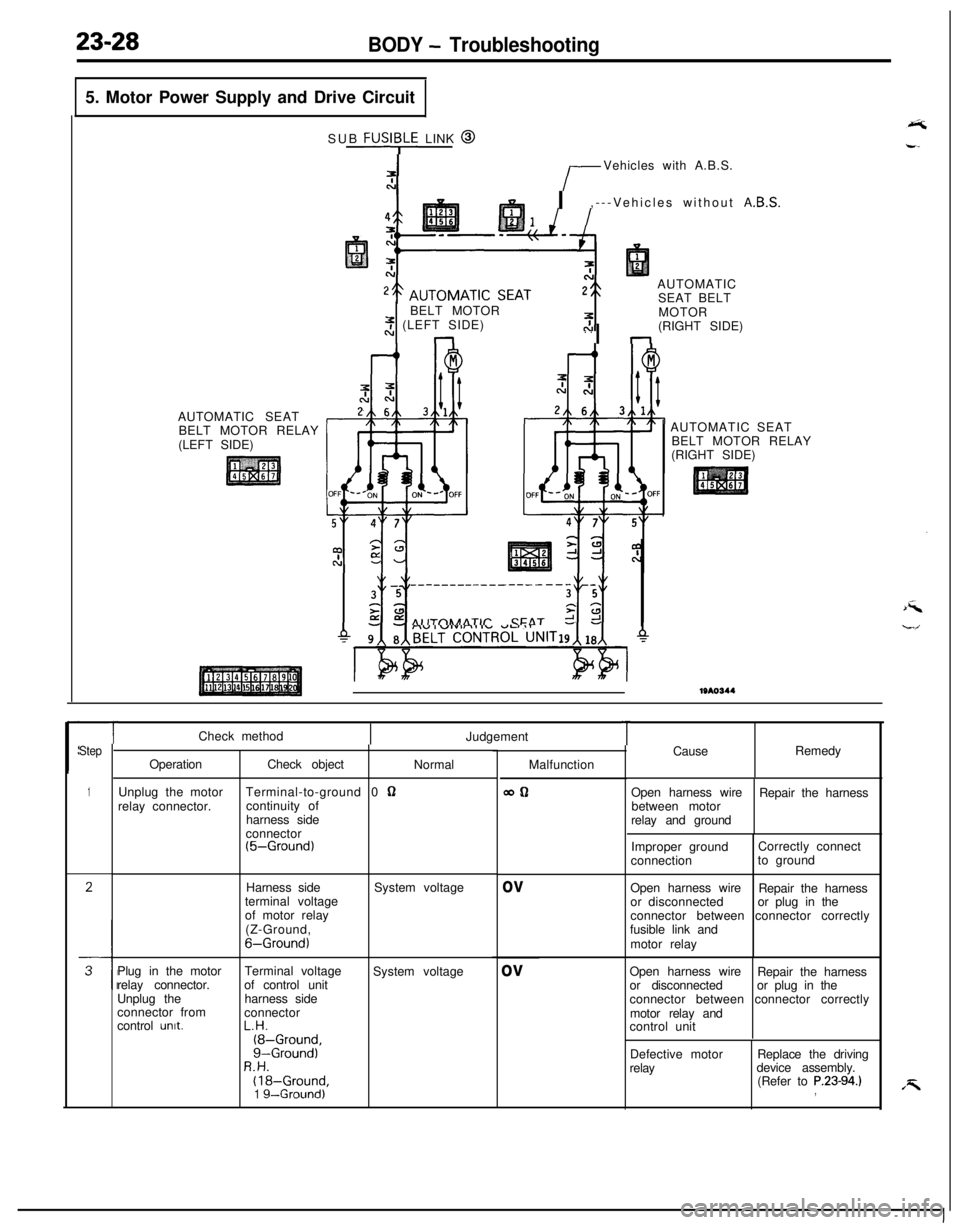
23-28BODY - Troubleshooting5. Motor Power Supply and Drive Circuit
AUTOMATIC SEAT
BELT MOTOR RELAY
(LEFT SIDE)SUB
FUSI;LE LINK @
r-Vehicles with A.B.S.
I,---Vehicles without A
AUTOMATIC
SEAT BELT
BELT MOTOR
2 (LEFT SIDE). .nI nMOTOR
(RIGHT SIDE)
AIITnhAATlr CFAT r!AUTOMATIC SEAT
BELT MOTOR RELAY
(RIGHT SIDE)1310344
Step
1
TCheck method
Judgement
OperationCheck object
Normal
Unplug the motorTerminal-to-ground 0
62relay connector.continuity of
harness side
connector
(5-Ground)Harness side
terminal voltage
of motor relay
(Z-Ground,
6-Ground)System voltage
Plug in the motorTerminal voltage
System voltage
relay connector.of control unit
Unplug theharness side
connector from
connector
control
unit.L.H.(8-Ground,g-Ground)R.H.(18-Ground,1 g--Ground)Malfunction
WQ
ov
ov
TCauseRemedy
Open harness wire
Repair the harness
between motor
relay and ground
Improper groundCorrectly connect
connectionto ground
Open harness wire
Repair the harness
or disconnectedor plug in the
connector between connector correctly
fusible link and
motor relay
Open harness wire
Repair the harness
or disconnectedor plug in the
connector between connector correctly
motor relay and
control unit
Defective motor
relayReplace the driving
device assembly.
(Refer to
P.23-94.),
Page 1073 of 1216
.-
BODY - Troubleshooting
AUTOMATIC SEAT BELT COMPONENTS LOCATION
WA0734
NameSymbolNameSymbolAutomatic seat belt control unit
CFasten switchAAutomatic seat belt motor
Automatic seat belt motor relay
Buckle switch
BuzzerDoor latch switch
EKey reminder switchI
DOuter switchF
GSeat belt warning lightJ
KRelease switchH
B--
A
P
(:0
Page 1111 of 1216
BODY - Door Glass and Reaulator/Power Window23-67
POWER WINDOW
REMOVAL AND INSTALLATIONSERVICE POINTS OF INSTALLATION3. APPLICATION OF GREASE TO FRONT DOOR WINDOW
REGULATORApply multipurpose grease to all moving parts.
Grease: MOPAR Multipurpose Grease Part No.
2932524 or equivalent
N23MHAEa
71l Door Window Glass Adjustment
< Passenger’s seat side >NOTE
(1) Reverse the removal procedures to reinstall.(2) l + : Refer to “Service Points of Installation”.
1810469Power window relay removal
1. Power window relay
Power window switch removal steps
Door trim (Refer to P.23-65.)2. Power window main switch
3. Power window sub switch
Power window motor removal steps
Door trim and waterproof film
(Refer to
P.23-65.)4. Door window glass
l + 5. Front door window regulator
16l.03443 416AO606
INSPECTIONPOWER WINDOW RELAY
Apply battery voltage to terminal 2, and check for continuity
when terminal 4 is grounded.
NOTEO-O indicates that there is continuity between the terminals.