Page 217 of 1216
BRAKES - Hydraulic Unit
HYDRAULIC UNIT
--. REMOVAL AND INSTALLATION
6Removal steps
I)+ 1. Brake tube connection
2. Relay box cover
3. Hydraulic unit harness connection
~~ l 4. Hydraulic unit5. Hydraulic unit bracket assembly
6. Bracket
7. Valve relay
1(Refer to GROUP
II-Intercooler.)Post-installation Operation
@Supplying Brake FluidaBleeding (Refer to P.5-45.)@Installation of Air Pipe B(Refer to GROUP II-Intercooler.)8. Motor relay
9. Connector bolt
10. Connector
11. Gasket
NOTE(1) Reverse the removal procedures to reinstall.
(2) +e : Refer to “Service Points of Removal”.
(3) e+ : Refer to “Service Points of Installation”.
Page 218 of 1216
5-78BRAKES - Hydraulic Unit
SERVICE POINTS OF REMOVAL
4. REMOVAL OF HYDRAULIC UNITb-3Remove the installation nuts, and then take out the __
hydraulic unit upward.
Caution
1. The hydraulic unit is heavy, and so care should be
taken when removing it.2. The hydraulic unit is not to be disassembled; its
nuts and bolts should absolutely not be loosened.
3. The hydraulic unit must not be dropped or other-
wise subjected to impact shocks.
4.The hydraulic unit must not be turned upside downor laid on its side.
Aotor relay
16R0670
16Rl773
INSPECTIONCheck whether there is continuity between terminals when
there is no current flow at each relay and when there is currentflow.
JlOTOR RELAY
Between
When noterminals @-@I
current flowsBetween
terminals @I-@
When current
flows between
Between
terminal
terminals @--@
@-@
30-60 52
No continuity
(WQ)
Continuity
(approx. 0 8)
Page 219 of 1216
BRAKES -Hydraulic Unit 5-79
Jalve relay
16R0670
87a
16Rl772
/ALVE RELAYBetween
terminals
@-@60-120 &2When noBetween
current flowsterminals
@I--@Continuity
(approx. 0 Q)Between
terminals
@J-QNo continuity(wQ2)When currentBetweenNo continuity
flows betweenterminals
@-@I(WQ)
terminal
@-@Between
terminals @--@Continuity
(approx. 0 S22)SERVICE POINTS OF INSTALLATION
4. INSTALLATION OF HYDRAULIC UNITFasten the ground wire to hydraulic unit bracket assembly.
1. CONNECTION OF BRAKE TUBEWhen connecting the tubes to the hydraulic unit, be sure
they are connected correctly.
(Refer to
P.5-64.)
Page 237 of 1216

CLUTCH - Clutch Pedal6-7
CLUTCH PEDAL
-. REMOVAL AND INSTALLATIONNOSPA-
.“-Pre-removal Operation
*Removal of the Lap Cooler Duct,Shower Duct (L.H.) and Knee Pro-tector (Refer to GROUP 23%lnstru-ment Panel.)*Removal of the Steering ColumnAssembly (Refer to GROUP 19-Steering Wheel and Shaft.)*Removal of the Relay Box (Indoor)
17-26 Nm
12-19 ft.lbs.
11-17 Nm
8-12 ft.lbs.
IO-15 Nm’ tl(i/\:/ Fl/Yv .1-m.---I- I I KIDS.Post-installation Operation
l installation of the Relay Box (Indoor)l installation of the Steering ColumnAssembly (Refer to GROUP 19-Steering Wheel and Shaft.)l installation of the Lap Cooler Duct,Shower Duct (L.H.) and Knee Pro-tector (Refer to GROUP 23 Instru-ment Panel.)l Adjustment of the Brake Pedal (Re-fer to GROUP 5-Service Adjust-ment Procedures.)aAdjustment of the Clutch Pedal (Re-
fer to P.6-5.)
!
:k -16
20-25 Nm
14-f8 ft.lbs.
Removal steps
I, Clutch pedal return spring 2. Brake pedal return spring3. Interlock switch
4. Clutch switch
control system>
5. Bolt
system>6. Stop light switch
7. Clip
l + 8. Bushing
9. Turn over spring
e+ IO. Bushing11. Cotter pinl + 12. Washerl + 13. Clevis pin14. Pedal support bracket assembly
15. Clutch pedal mounting nut
16. Clutch pedal bracket17. Lever
l + 18. Clutch pedal bushing~~ 19. Clutch pedal bushing
20. Pedal rod
e+ 21. Brake pedal bushings
22. Clutch pedal
23. Brake pedal
24. Pedal pad
NOTE(1) Reverse the removal procedures to reinstall.(2) l + : Refer to “Service Points of (3) m : Non-reusable parts
Page 253 of 1216

COOLING - Troubleshootina7-5
TRO,UBLESHOOTlNG
Symptom
OverheatProbable causeInsufficient engine coolant
Too high an anti-freeze concentrationRemedy
Replenish
Correct anti-freeze
concentration
Loose or broken drive belt
Replace
Inoperative electric cooling fan
Faulty thermosensor
Replace
Faulty electrical motorReplace
Faulty radiator fan relayReplace
Damaged or blocked (insufficiently ventilated) radiator finsCorrect
Water leaks
Damaged radiator core joint
Replace
Corroded or cracked hosesReplace
(radiator hose, heater hose, etc.)
Loose bolt or leaking gasket in water outlet fitting
(thermostat)
Loose water pump mounting bolt or leaking gasket
Faulty cap valve or setting of spring
Loose intake manifold bolts or leaking from gasket
Cracked intake manifold
Faulty automatic transaxle oil cooler operation
Blocked or collapsed hose and pipe
Loose hose and pipe connection
Faulty thermostat operation
Faulty water pump operation
Water passage clogged with slime or rust deposit or
foreign substanceCorrect or replace
Correct or replace
Replace
Retorque bolts or replace
gasket
Replace
Replace
Correct
Replace
Replace
Clean
Jo rise in temperatureFaulty thermostatReplace
Page 254 of 1216
7-6COOLING - Troubleshooting
CIRCUIT DIAGRAM
ON(IG2)SUB FUSIBLE LINK @IGNI:SWIT(: LINK@MAIN FUSIB:
0
.-----
IN
1
A-18X
1CONDENSER
A-20X ,
I!31P2
RESISTOR
(CONDENSER'
FAN MOTOR,
A-32
m
A-21
IQ
Ed3B4SB
CONDENSER$l
FAN MOTOR2
12
lal34I
A-32
0
I
I
CONDENSER FAN
MOTOR RELAYA-03X
I 2lm34
A-22
CONDENSER
t----lTH RMOBE 80R
;;aIATOR ci
ASSEMBLY'
C-72
RADIATORFANMOTOR (
A-40
II
i0
A
6
KX35-AC-U0802-NC
Page 255 of 1216

COOLING - Troubleshooting7A7
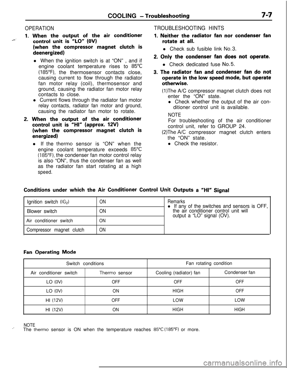
OPERATION
1. When the output of the air conditioner*--control unit is “LO” (OV)(when the
compressor magnet clutch isdeenergized)
l When the ignition switch is at “ON” , and if
engine coolant temperature rises to
85°C
(185”F), the thermosensor contacts close,
causing current to flow through the radiator
fan motor relay (coil), thermosensor and
ground, causing the radiator fan motor relay
contacts to close.
l Current flows through the radiator fan motor
relay contacts, radiator fan motor and ground,causing the radiator fan motor to rotate.
2. When the output of the air conditioner
control unit is “HI” (approx. 12V)(when the
compressor magnet clutch is
energized)l If the therm0 sensor is “ON” when the
engine coolant temperature exceeds
85°C
(185°F). the condenser fan motor control relay
is also “ON”, thus the condenser fan as well
as the radiator fan start rotating at a high
speed.
TROUBLESHOOTING HINTS
1. Neither the radiator fan nor condenser fanrotate at
all.l Check sub fusible link
No.3.
2. Only the condenser fan does not operate.l Check dedicated fuse
No.5.
3. The radiator fan and condenser fan do notoperate
in the low speed mode, but operateotherwise.
(1)The A/C compressor magnet clutch does not
enter the “ON” state.
l Check whether the output of the air con-
ditioner control unit is available.
NOTEFor troubleshooting of the air conditioner
control unit, refer to GROUP 24.
(2)The A/C compressor magnet clutch enters
the “ON” state.
l Check the resistor.Conditions
under which the Air Conditioner Control Unit Outputs a “HI” Signal
Ignition switch (IG2)
Blower switchAir conditioner switch
Compressor magnet clutch
ON
ON
ON
ON
Remarksl If any of the switches and sensors is OFF,
the air conditioner control unit will
output a “LO” signal (OV).
Fan Operating Mode
Switch conditions
Air conditioner switch
Therm0 sensor
LO
(OV)OFFLO
(OV)ONHI
(12V)OFFHI
(12V)ONFan rotating condition
Cooling (radiator) fanCondenser fan
OFFOFF
HIGHOFF
LOWLOW
HIGHHIGH
NOTE
_-The therm0 sensor is ON when the temperature reaches 85°C (185°F) or more.
Page 262 of 1216

7-14COOLING - Radiator
A
OFF
ON
h
--- ,
BWatertemperature
16v1100
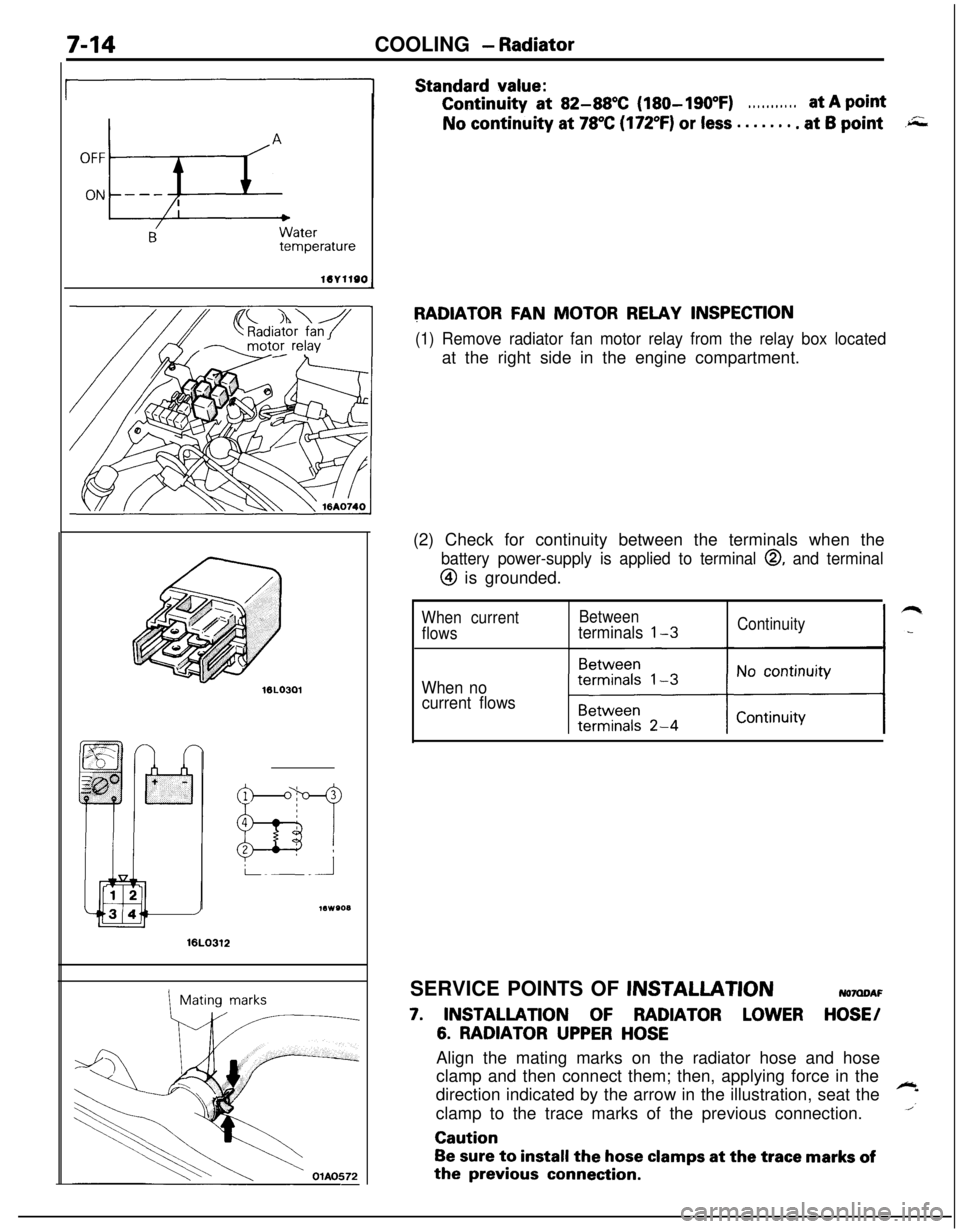
Standard value:Continuity
at 82-88X (180-190°F). . . . . . . . . . .at A pointNo continuity at
78°C (172°F) or less . . . . . . . . at 6 point.r;;;
RADIATOR FAN MOTOR RELAY INSPECTION
(1) Remove radiator fan motor relay from the relay box locatedat the right side in the engine compartment.
16LO312
1Mating marks(2) Check for continuity between the terminals when the
battery power-supply is applied to terminal 0, and terminal
@ is grounded.
When currentBetween
flowsterminals l-3Continuity
When no
current flowsSERVICE POINTS OF
JNSTALLATIONNOMDAF
7. INSTALLATION OF RADIATOR LOWER HOSE/
6. RADIATOR UPPER HOSEAlign the mating marks on the radiator hose and hose
clamp and then connect them; then, applying force in the
direction indicated by the arrow in the illustration, seat the
~
1clamp to the trace marks of the previous connection.Caution
Be sure to install the hose clamps at the trace marks ofthe
previous connection.