Page 1115 of 1216
BODY - Central Door Locking System/Door Runchannel23-71View A
18A0064-
L
DOOR RUNCHANNEL
REMOVAL AND INSTALLATION
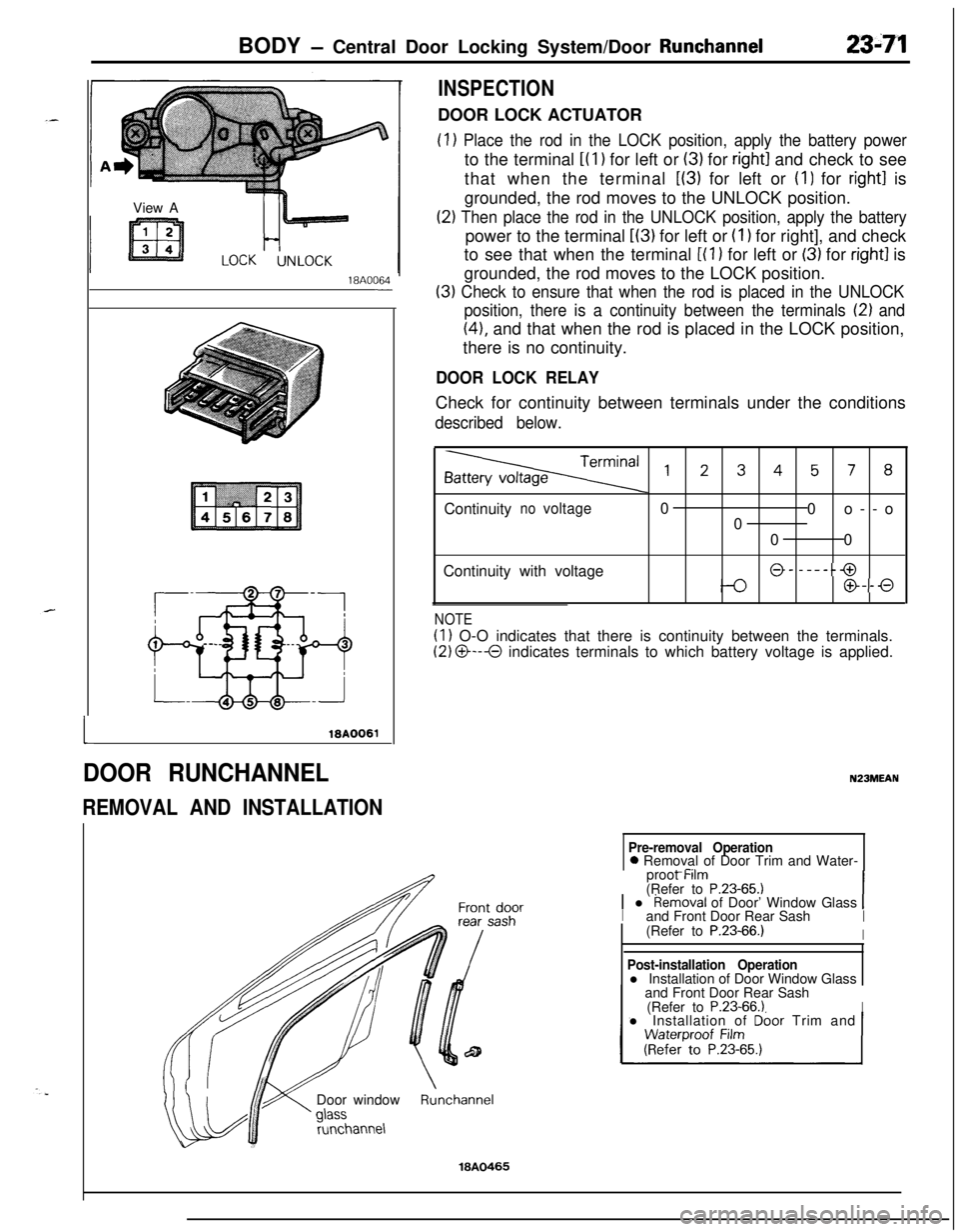
INSPECTIONDOOR LOCK ACTUATOR
(1) Place the rod in the LOCK position, apply the battery powerto the terminal
i(l) for left or (3) for right1 and check to see
that when the terminal
L(3) for left or (I) for right1 is
grounded, the rod moves to the UNLOCK position.
(2) Then place the rod in the UNLOCK position, apply the batterypower to the terminal
L(3) for left or (I 1 for right], and check
to see that when the terminal
[(l ) for left or (3) for right1 is
grounded, the rod moves to the LOCK position.
(3) Check to ensure that when the rod is placed in the UNLOCK
position, there is a continuity between the terminals
12) and
(41, and that when the rod is placed in the LOCK position,
there is no continuity.
DOOR LOCK RELAYCheck for continuity between terminals under the conditions
described below.
,2345, 8Continuity
novoltage0
0o--o
0
00
Continuity with voltage
@- -----@
@--0
NOTE
(1) O-O indicates that there is continuity between the terminals.
(2) O---O indicates terminals to which battery voltage is applied.
N23MEAN
Pre-removal Operation0 Removal of Door Trim and Water-
_ -..proot Mm
(Refer to
P.23-65.11 l Removal of Door’ Window Glass 1Iand Front Door Rear SashI(Refer to P.23-66.)IDoor window
runchannel
Post-installation Operationl Installation of Door Window Glass
and Front Door Rear Sash
(Refer to
P.23-66.1Il Installation of Dbor Trim and
Runchannel
18A0465
Page 1139 of 1216
BODY - Seat Belt23-9535-55 Nm
25-40 ft.lbs.\17-26 Nm
Shoulder belt removal steps
10. Guide ring
1 1. Shoulder beltc*12. Floor console assembly22. Outer switch connector connection
23. Retractor assembly (for shoulder belt)
19A0309
Buzzer removal stepsInstrument panel assembly24
(gy;ZfieerrtO P.23-80.)
NOTE(1) Reverse the removal procedures to reinstall.(2) +e : Refer to “Service Points of Removal”
19A0319
SERVICE POINTS OF REMOVAL
12. REMOVAL OF FLOOR CONSOLE ASSEMBLYRefer to
P.23-84.14. REMOVAL OF FRONT SEAT ASSEMBLY
Refer to
P.23-90.19. REMOVAL OF DOOR LATCH SWITCH
Refer to
P.23-69.
INSPECTION
MOTOR
(1) Unplug the automatic seat belt motor relay connector.
(2) Connect the terminals (indicated in the illustration) of the
automatic seat belt wiring harness connector directly to the
battery, and check that the motor operates smoothly. Next,reverse the polarity and check that the motor operates
smoothly in the reverse direction.
Page 1140 of 1216
23-96BODY - Seat Belt
Q ET19A0316
I) : Terminal to checkthe release switch
I+ : Terminal to check
the fasten switchlQA0316
16A07.51
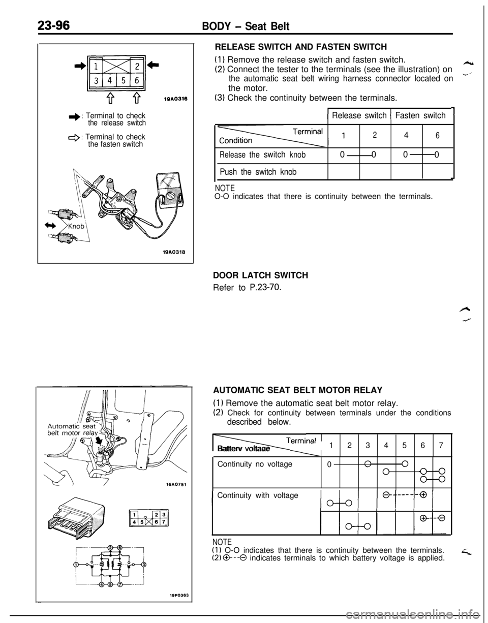
19PO363RELEASE SWITCH AND FASTEN SWITCH
(1) Remove the release switch and fasten switch.
(2) Connect the tester to the terminals (see the illustration) on*
the automatic seat belt wiring harness connector located on-’the motor.
(3) Check the continuity between the terminals.
11 Release switch 1 Fasten switch
Releasetheswitchknob
Push the switch knob
246000
0
NOTEO-O indicates that there is continuity between the terminals.
DOOR LATCH SWITCH
Refer to
P.23-70.AUTOMATIC SEAT BELT MOTOR RELAY
(1) Remove the automatic seat belt motor relay.
(2) Check for continuity between terminals under the conditions
described below.
Termi, lalIIBatterv voltaae
m-al1234567
Continuity no voltage
0
n 0”0
IContinuity with voltageIIIIIIII
NOTE(1) O-O indicates that there is continuity between the terminals.(2) O---O indicates terminals to which battery voltage is applied.
Page 1143 of 1216
BODY - Seat Belt23-99
19AO239
I ITest bulb 2tI
I I
INSPECTION
SEAT BELT TIMERRemove the seat belt timer from the relay box (indoor).
TIMER OPERATION CHECK(I
1 Connect the battery and the test bulb to the timer, as shown
in the illustration.
(2) Make sure that when terminal 2 is connected to the positive
(+) terminal of the battery, test bulbs 1 and 2 are lighted
for approx. 6 seconds.
(3) Make sure that even when terminal 3 is disconnect while testbulbs 1 and 2 and lighted in
(2) above, test bulb 1 remains
lighted.
BUCKLE SWITCHRefer to
P.23-97.
BUZZERRefer to
P.23-97.
SERVICE POINTS OF INSTALLATION7. INSTALLATION OF FRONT SEAT BELT
Fit the retractor retaining lug in the slot provided in the
vehicle body, and secure the retractor with the bolt by
tightening it to the specified torque.
Page 1145 of 1216
24-l
HEATERS ANDAIR CONDITIONING
CONTENTSN24M--AIR CONDITIONER SWITCH
..........................30BLOWER ASSEMBLY
.....................................33
COMPRESSOR.................................................37CONDENSER AND CONDENSER FAN
MOTOR............................................................45ENGINE COOLANT TEMPERATURE
-‘-.,SWITCH............................................................51
EVAPORATOR.................................................
34
HEATERCONTROLASSEMBLY....................
26HEATER UNIT
.................................................31
REFRIGERANTLINE........................................47
RESISTOR........................................................29SAFETY PRECAUTIONS
.................................10SERVICE ADJUSTMENT PROCEDURES..
.....11Compressor Drive
Belt Adjustment
.............
23
CompressorNoise........................................24
Handling
TubingandFittings.......................22Idle-up
OperationCheck..............................25Manifold
GaugeSetInstallation..................11Performance Test
.........................................16Power Relay Check
......................................24Refrigerant Leak Repair Procedure
.............17
TestingSystemforLeaks...........................15Test Procedures
...........................................11
SPECIFICATIONS.............................................2
General Specifications..................................2
Lubricants......................................................3Sealant and Adhesives
.................................3Service Specifications
...................................2
TorqueSpecifications...................................2
TROUBLESHOOTING. . . ..a................................3
VENTILATORS(AIR INLET AND AIR OUTLET)
..,....s............. 50
VENTILATORS(INSTRUMENT PANEL)
..,...................*...........49
Page 1147 of 1216

HEATERS AND AIR CONDITIONING - Specifications/Troubleshooting24-3LUBRICANTS
u24as-
;xiItemsSpecified lubricantsQuantity
Each connection of refrigerant lineDENS0 OIL 6 or
SUNISO 5GSAs required
Shaft seal of the compressor
SEALANT AND ADHESIVES, Items
Engine coolant temperature switch threaded partSpecified sealant and adhesive
MOPAR Part No.4318034 or equivalentN24CE-
TROUBLESHOOTINGN24EBAQ
SymptomHeater insufficient heat
No ventilation even when
mode selection knob is
operatedBlower motor inoperative
Probable causeObstructed heater outlets
Blend air dampers improperly adjusted or bindingThermostat malfunction
Obstructed heater hoses
Improperly adjusted control cables
Plugged or partially plugged heater core
Incorrect adjustment of mode selection dampersIncorrect installation of mode selection control wire
Ducts are incorrectly/incompletely connected, crushed,
bent or clogged.
Poor grounding
Burnt-out fuseMalfunction blower switch
Malfunction resister
Malfunction blower motor
Malfunction heater relay
Remedy
Correct
ReplaceAdjust
Clean or replaceAdjust
Repair or replace
Correct
Replace
Page 1148 of 1216
24-4HEATERS AND AIR CONDITIONING - Troubleshooting
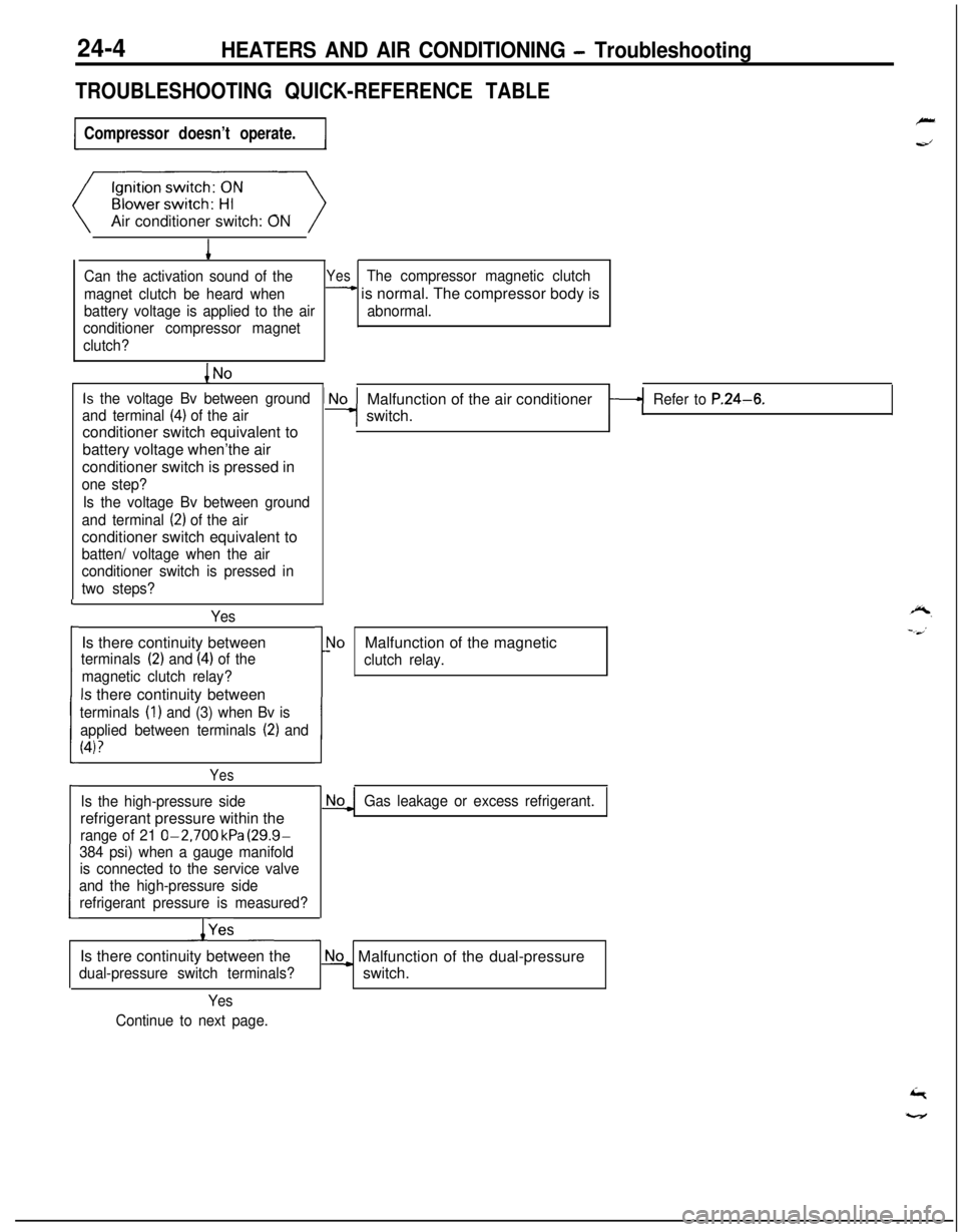
TROUBLESHOOTING QUICK-REFERENCE TABLE
Compressor doesn’t operate.Air conditioner switch: ON
1
Can the activation sound of theYesThe compressor magnetic clutch
magnet clutch be heard when
- is normal. The compressor body is
battery voltage is applied to the airabnormal.
conditioner compressor magnet
clutch?
Is the voltage Bv between ground
and terminal
(4) of the airconditioner switch equivalent to
battery voltage when’the air
conditioner switch is pressed in
one step?
Is the voltage Bv between ground
and terminal
(2) of the airconditioner switch equivalent to
batten/ voltage when the air
conditioner switch is pressed in
two steps?
YesIs there continuity between
terminals (2) and (4) of the
magnetic clutch relay?
Is there continuity between
terminals (1) and (3) when Bv is
applied between terminals
(2) and
(4)?
L
i
I
Yes
Is the high-pressure siderefrigerant pressure within the
range of 21 O-2,700 kPa (29.9-
384 psi) when a gauge manifold
is connected to the service valve
and the high-pressure side
refrigerant pressure is measured?
/YesMalfunction of the air conditioner
switch.
Refer to P.24-6.
r
1!
\loMalfunction of the magnetic
clutch relay.
Gas leakage or excess refrigerant.Is there continuity between the
dual-pressure switch terminals?
No_ Malfunction of the dual-pressure
switch.
Yes
Continue to next page.
Page 1150 of 1216
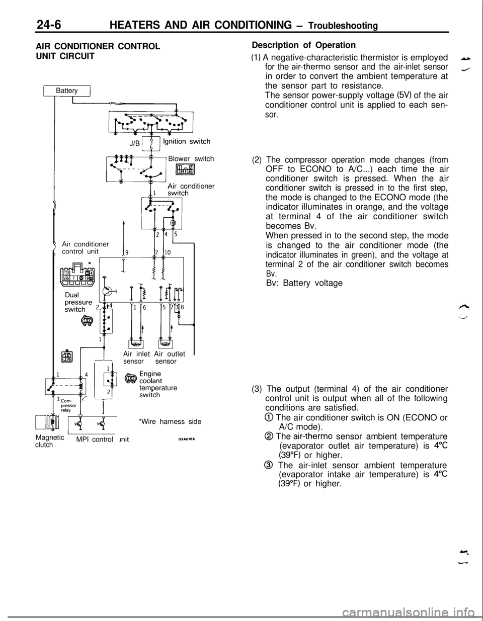
24-6HEATERS AND AIR CONDITIONING - TroubleshootingAIR CONDITIONER CONTROL
UNIT CIRCUIT
1 Battery IBlower switch
litalAir conditioner
IAir inlet Air outlet1-isensorsensor
temperature
Corn- L Tpressor
relayI IMagnetic
AclutchMPI control*Wire harness sideDescription of Operation
(1) A negative-characteristic thermistor is employed
for the air-therm0 sensor and the air-inlet sensorin order to convert the ambient temperature at
the sensor part to resistance.
The sensor power-supply voltage
(5V) of the air
conditioner control unit is applied to each sen-
sor.
(2) The compressor operation mode changes (fromOFF to ECONO to A/C...) each time the air
conditioner switch is pressed. When the air
conditioner switch is pressed in to the first step,the mode is changed to the ECONO mode (the
indicator illuminates in orange, and the voltage
at terminal 4 of the air conditioner switch
becomes Bv.
When pressed in to the second step, the mode
is changed to the air conditioner mode (the
indicator illuminates in green), and the voltage at
terminal 2 of the air conditioner switch becomes
Bv.Bv: Battery voltage
(3) The output (terminal 4) of the air conditioner
control unit is output when all of the following
conditions are satisfied.
@ The air conditioner switch is ON (ECONO or
A/C mode).
@ The air-therm0 sensor ambient temperature
(evaporator outlet air temperature) is
4°C
(39°F) or higher.
@ The air-inlet sensor ambient temperature
(evaporator intake air temperature) is
4°C
(39°F) or higher.