Page 377 of 1216

ENGINE <2.0L DOHC Engine> - Cylinder Head Gasket9-93
DlADD3fFront of
engine+Exhaust side
OlR0391Cylinder
he/d-Ani-circularpackingSERVICE POINTS OF INSTALLATIONNOSJDDls
48. INSTALLATION OF CYLINDER HEAD GASKET
(1)Use a scraper to clean the gasket surface of the cylinder
block.
Caution
Take care that no foreign material gets into the
cylinder, or into coolant passages or oil passages.(2) Make sure that the gasket has the proper identification
mark for the engine.
(3) Lay the cylinder head gasket on the cylinder block with
the identification mark at the front top.
47. INSTALLATION OF CYLINDER HEAD ASSEMBLY
(1)Use a scraper to clean the gasket surface of the cylinderhead assembly.
Caution
Take care that no foreign material gets into the
coolant passages or oil passages.(2) Using the special tool and a torque wrench, tighten the
bolts to the specified torque in the order shown in the
figure. (in two or three cycles)
Caution
Install the head bolt washers as shown in the
diagram.
41. APPLICATION OF SEALANT TO SEMI-CIRCULAR PACK-
ING
Apply a coating of the specified sealant to the semi-circularpacking and the cylinder head to top surfaces.
Specified sealant: MOPAR Part No.4318034 or equiva-
lent
Page 386 of 1216

S-102ENGINE <2.0L DOHC Engine> - Timing Belt
Crankshaftsyocket “B”
Crankshaft
sprocketdrankshaft 6fN272
6EN I1231. INSTALLATION OF
FLANGEInstall the flange in correct direction as shown.
Caution
Pay special attention to the direction of the flange. If it
is installed in the wrong direction, a broken timiiig ‘beltcould result.
30. INSTALLATION OF CRANKSHAFT SPROCKET
Install the crankshaft sprocket in the correct direction as
shown.Caution
Pay special attention to the direction of the flange. If it
is installed in the wrong direction, a broken timing belt
could result.
27. INSTALLATION OF OIL PUMP SPROCKET
(1) Insert a Phillips screwdriver [shank diameter 8 mm
(.31in.) shaft] through the plug hole on the left side of
cylinder block to block the left silent shaft.
(2) Install the oil pump sprocket.
(3) Tighten the nut to the specified torque.
26. INSTALLATION OF CAMSHAFT SPROCKETS
Using a wrench, hold the camshaft at its hexagon (betweenthe
No.2 and No. 3 journals) and tighten the bolt to
specification.Caution
Locking the camshaft sprocket with a tool damages the
sprocket.
Page 390 of 1216

9-106ENGINE <2.0L DOHC Engine> - Timing Belt. ADJUSTMENT OF TIMING BELT TENSION
(1) After turning the crankshaft
l/4 turn counterclockwise,.5;;turn it clockwise to move the No. 1 cylinder to top dead
center.(2) Loosen the center bolt, and then, as shown in the
illustration, attach the special tool and a torque wrench
and apply a torque of 2.6-2.8 Nm
(1.88-2.03 ft.lbs.).If the body interferes with the special tool and the
torque wrench, use a jack to slightly raise the engine
assembly.
NOTEUse a torque wrench that is capable of measurement
within a range of
O-3 Nm (O-2.2 ft.lbs.).(3) Holding the tensioner pulley with the special tool and
torque wrench, tighten the center bolt to specification.
(4) Screw the special tool into the engine left support
bracket until its end makes contact with the tensioner
arm. At that point, screw the special tool in some more
and then remove the set wire attached to the auto
tensioner.(5) Remove the special tool.
(6) Rotate the crankshaft two complete turns clockwise
and leave it as is for about 15 minutes. Then, measure
the auto tensioner protrusion “A” (distance between
the tensioner arm and auto tensioner body) to ensure,.+
that it is up to specification.
Standard value:
3.8-4.5 mm (.15-.18 in.)
If it is out of specification, repeat steps (6) through (1)
until the specified value is obtained.
(7) If the clearance between the tensioner arm and the
auto tensioner body cannot be measured (when the
engine is being mounted, etc.), the following proce-
dures can be used to substitute for the ordinan/ methodof measurement.
@ Screw in the special tool until it contacts the
tensioner arm.
@ From that point of contact, further screw in the
special tool, screwing it in until the push rod of the
auto tensioner body is caused to move backward
and the tensioner arm contacts the auto tensioner
body.Check to be sure that the amount that the special
tool has been screwed in (when the push rod
moves backward) is the standard value.
Standard value: 2.5-3 turns
Page 400 of 1216
9416
I
ENGINE <2.0L DOHC Engine> - Cylinder Head and Valve
I1. INSTALLATION OF CYLINDER HEAD BOLTS
(1) Using the special tool, tighten the cylinder head bolts.
G Front of engine (Timing belt side)(2) Tighten the cylinder head bolts in the sequence shown.
Each bolt should be tightened in two to three steps,
torquing progressively. Tighten to specified torque in
the final sequence.
Page 409 of 1216
ENGINE <2.0L DOHC Engine> -Front Case, Oil Pump and Silent Shaft9-1256E
N026:(2) Install the front case assembly through a new front
case gasket and temporarily tighten the flange bolts
(other than those for tightening the filter bracket).
(3) Mount the oil filter bracket with oil filter bracket gasket.
Then, install the four bolts with washers.
(4) Tighten the bolts to specification.
NOTE
Bolts indicated by the * symbol should be tightened at atorque of 27-34 Nm
(20-25 ft.1b.s.).20. INSTALLATION OF DRIVEN GEAR BOLT
(1) Insert a Phillips screwdriver into a hole in the left side ofthe cylinder block to lock the silent shaft.
(2) Secure the oil pump driven gear onto the left silent
shaft by tightening the driven gear bolt to specified
torque.18. INSTALLATION OF PLUG CAP
(1) Install a new O-ring to the groove of front case.
(2) Using the special tool, install the plug cap and tighten tospecified torque.
Page 417 of 1216

ENGINE <2.0L DOHC Engine>- Crankshaft, Flywheel and Drive Plate,91133
INSPECTIONNOSUHAD
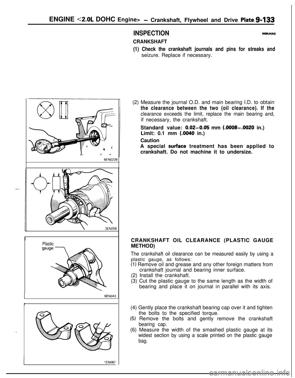
CRANKSHAFT(1) Check the crankshaft journals and pins for streaks and
seizure. Replace if necessary.
6EN0’228
\3EN056
Plastic
6EN043
. .
I1 EN067-(2) Measure the journal O.D. and main bearing I.D. to obtain
the clearance between the two (oil clearance). If the
clearance exceeds the limit, replace the main bearing and,if necessary, the crankshaft.
Standard value:
0.02-0.05 mm (.OOOS-.0020 in.)
Limit: 0.1 mm
(.0040 in.)
Caution
A special
surface treatment has been applied to
crankshaft. Do not machine it to undersize.
CRANKSHAFT OIL CLEARANCE (PLASTIC GAUGE
METHOD)
The crankshaft oil clearance can be measured easily by using aplastic gauge, as follows:
(1) Remove oil and grease and any other foreign matters from
crankshaft journal and bearing inner surface.
(2) Install the crankshaft.
(3) Cut the plastic gauge to the same length as the width of
bearing and place it on journal in parallel with its axis.
(4) Gently place the crankshaft bearing cap over it and tighten
the bolts to the specified torque.
(5) Remove the bolts and gently remove the crankshaft
bearing cap.(6) Measure the width of the smashed plastic gauge at its
widest section by using a scale printed on the plastic gauge
bag.
Page 423 of 1216

11-l
INTAKE AND
EXHAUSTAIR CLEANER
. . . . . . . ..*........................................8
EXHAUST MANIFOLD <1.8L Engine> . . . . . . . .26
EXHAUST MANIFOLD
<2.0L DOHC Engine
(Non-Turbo)>
. . . . . . ..*.*.......................................27EXHAUST MANIFOLD
<2.0L DOHC Engine
(Turbo)>
. . . . . . . . . . . . . . . . . . . . . . . . . . . . . .*...........................28
CONTENTSNllAA--
-EXHAUST PIPE AND MAIN MUFFLER<1.8L Engine,
2.0L DOHC Engine
(Non-Turbo)>
. . . . . . . . . . . . . . . . . . . . .. . . . . . . . . . . . . . . . . . . . . . . . . . . . .30EXHAUST PIPE AND MAIN MUFFLER<2.0L
DOHCEngine(Turbo)>. . . . . . . . . . . . . . . . . . . . .31INTAKE MANIFOLD
<1.8LEngine> . . . . . . . . . . . .13INTAKE MANIFOLD
<2.0L DOHC Engine> 17
INTERCOOLER. . . . . . . . . . . . . . . . . . . . . . . . . . . . . . . . . . . . . . . . . . . . . . . . .11SERVICE ADJUSTMENT PROCEDURES..
.....5Air
Bypass ValveInspection........................7Air Cleaner Element Inspection and
Replacement . .
. . . . . . . . . . . . . . . . . . . . . . . . . . . . . . . . . . . . . . . . . . . . .5Supercharging Pressure Control System
Inspection
.,...... . . . . . . . . . . . . . . . . . . . . . . . . . . . . . . . .. . . . . . . . . . . . . .6Supercharging Pressure Relief Solenoid
Valve Inspection
. . . . . . . . . . . . . . . . . . . . . . . . . . . . . . . . . . . . . . . . . . .7Turbocharger Supercharging Pressure
Inspection. . . . . . . . . . . . . . . . . . . . . . . . . . . . . . . . . . . . . . . . . . . . . . . . . . . . . .6SPECIAL TOOL
. . . . . . . . . . . . . . . . . . . . . . . . . . . . . ..#................4
SPECIFICATIONS.............................................2General Specifications
..................................2Service Specifications
...................................2Torque Specifications
...................................2
TROUBLESHOOTING. . . . . . . . . . . . . . . . . . . . . . . . . . . . . . . . . . . . . .4
Abnormal Noise
Exhaust Gas Leakage
TURBOCHARGER
. . . . . . . . . . . . . . . . . . . . . . . . . . . . . . . . . . . . . . . . . . . .20
Page 424 of 1216

11-2INTAKE AND EXHAUST - Specifications
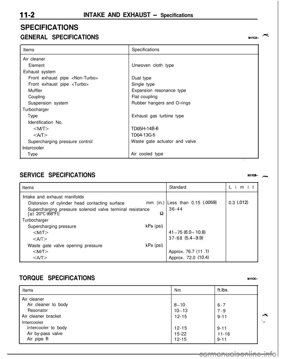
SPECIFICATIONS
GENERAL SPECIFICATIONS.prtNIICA-Items
Air cleaner
ElementExhaust system
Front exhaust pipe
Front exhaust pipe
Muffler
CouplingSuspension system
Turbocharger
TypeIdentification No.
4iT>Supercharging pressure control
Intercooler
TypeSpecifications
Unwoven cloth type
Dual type
Single type
Expansion resonance type
Flat coupling
Rubber hangers and O-rings
Exhaust gas turbine type
TD05H-14B-6
TD04-13G-5Waste gate actuator and valve
Air cooled type
SERVICE SPECIFICATIONSNllCB- spr*
ItemsStandardIntake and exhaust manifolds
Distorsion of cylinder head contacting surfacemm (in.) Less than 0.15
(.0059)Supercharging pressure solenoid valve terminal resistance36-44
[at
20°C (68”F)lQ
TurbochargerSupercharging pressure
kPa (psi)
41-75 (6.0- 10.8)
37-68 (5.4-9.9)Waste gate valve opening pressure
kPa (psi)
Approx. 76.7 (11 .l)
Approx. 72.0 (10.4)Limit
0.3
l.0121
TORQUE SPECIFICATIONSNllCC-
ItemsAir cleaner
Air cleaner to body
ResonatorAir cleaner bracket
Intercooler
Intercooler to body
Air by-pass valve
Air pipe
B
Nmftlbs.
8-106-7
10-137-9
12-15
9-11
12-15
9-11
15-22
11-16
12-15
9-11