1991 MITSUBISHI ECLIPSE torque
[x] Cancel search: torquePage 427 of 1216

INTAKE AND EXHAUST - Service Adjustment Procedures11-5
SERVICE ADJUSTMENT PROCEDURES
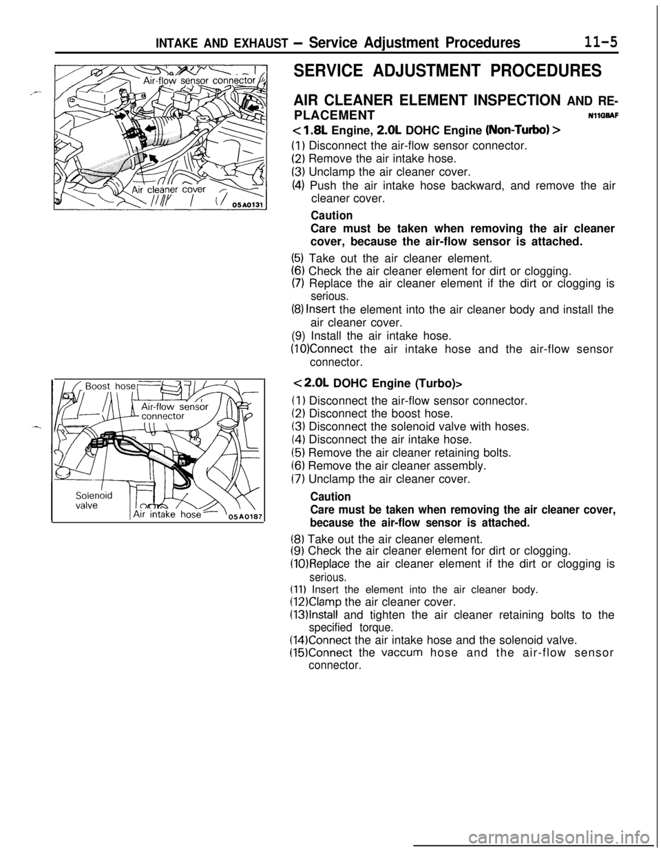
AIR CLEANER ELEMENT INSPECTION AND RE-PLACEMENTNllQBAF
< 1.8L Engine, 2.0L DOHC Engine (Non-Turbo) >
(1) Disconnect the air-flow sensor connector.
(2) Remove the air intake hose.
(3) Unclamp the air cleaner cover.
(4) Push the air intake hose backward, and remove the air
cleaner cover.
CautionCare must be taken when removing the air cleaner
cover, because the air-flow sensor is attached.
(5) Take out the air cleaner element.
(6) Check the air cleaner element for dirt or clogging.
(7) Replace the air cleaner element if the dirt or clogging is
serious.
(8) Insert the element into the air cleaner body and install the
air cleaner cover.
(9) Install the air intake hose.
(10)Connect the air intake hose and the air-flow sensor
connector.
<2.0L DOHC Engine (Turbo)>(I
1 Disconnect the air-flow sensor connector.
(2) Disconnect the boost hose.
(3) Disconnect the solenoid valve with hoses.
(4) Disconnect the air intake hose.
(5) Remove the air cleaner retaining bolts.
(6) Remove the air cleaner assembly.
(7) Unclamp the air cleaner cover.
Caution
Care must be taken when removing the air cleaner cover,
because the air-flow sensor is attached.
(8) Take out the air cleaner element.
(9) Check the air cleaner element for dirt or clogging.
(10)Replace the air cleaner element if the dirt or clogging is
serious.
(11) Insert the element into the air cleaner body.
(12)Clamp the air cleaner cover.
(13)lnstall and tighten the air cleaner retaining bolts to the
specified torque.
(14)Connect the air intake hose and the solenoid valve.
(15)Connect the vaccum hose and the air-flow sensor
connector.
Page 455 of 1216

14-IFUEL SYSTEM
CONTENTS
AUTO-CRUISECONTROLSYSTEM...........................................109AUTO-CRUISECONTROL.......................................................140SERVICEADJUSTMENTPROCEDURES..............................135Accelerator Cable, Throttle Cable and Auto-cruise
ControlCableInspectionandAdjustment........................136Auto-cruise
ControlSystemInspection.............................135lndrvrdualPartsInspection..................................................137SPECIFICATIONS.....................................................................109GeneralSpecifications.......................................................109ServiceSpecifications
.........................................................109Torque Specrfications..........................................................109TROUBLESHOOTING...............................................................110Auto-CruiseControlCircurt................................................128Auto-cruise
ControlComponentsLocation........................126Auto-cruise Control Related Harnesses
.............................125Check Chart
........................................................................114Input Check.........................................................................123Self-diagnosis
Check..........................................................121Troubleshootrng
Quick-referenceChart..............................110ENGINECONTROL.......................................................................105ENGINECONTROL..................................................................107--SERVICEADJUSTMENTPROCEDURES..............................106Accelerator Cable Inspection and Adjustment..................106Accelerator Switch Inspectron and Adjustment................106SPECIFICATIONS.....................................................................105Lubricants.............................................................................105Sealant.................................................................................105ServiceSpecifications
..........................................................105TorqueSpecifications..........................................................105TROUBLESHOOTING...............................................................105FUELSYSTEM..............................................................................2FUELFILTER............................................................................104FUELLINEANDVAPORLINE..............................................102FUEL PUMP, FUEL GAUGE UNIT ANDOVERFILL LIMITER(TWO-WAY VALVE)
Switch........................................................64Air Conditioner Power Relay
..............................................67Components
Location......................................................56
ControlRelay
.................................................................66EGRControlSolenoidValve...............................................67EGRTemperatureSensor..................................................64Engine Coolant Temperature Sensor
.................................62IdlePosrtionSwitch
...........................................................63IdleSpeedControlServo
.............................
....................65InhibitorSwitch....................................................................65hjeCtOrS................................................................................65IntakeAirTemperatureSensor..........................................6’2MalfunctionlndtcatorLight
..........................................58MotorPosition
Sensor................................................63OxygenSensor
.................................................................64Power Steering 011 Pressure Swatch...........................65PowerTransistor
................................................................67PurgeControlSolenoidValve.........................................67
Self-Diagnosis.......................................................................
ThrottlePositronSensor.....................................................
Vehicle Speed Sensor.........................................................MPI
SYSTEMINSPECTION<2.0L DOHCEngine>...........Air Conditioner Power Relay..............................................
Arr Conditioner Swatch........................................................
Components Location
.........................................................
Control
Relay.......................................................................
EGR Control Solenoid Valve...............................................
EGR Temperature Sensor
...................................................
Engine Coolant Temperature Sensor
.................................Fuel Pressure Control Valve...............................................
Idle Position Switch
............................................................
Idle
SpeedControlServo...................................................Injectors
................................................................................
Intake Air Temperature Sensor..........................................
Malfunction Indicator Light.................................................
Oxygen Sensor
....................................................................
Power
Steering
OilPressureSwitch.................................Power Transistor
.................................................................
Purge Control Solenoid Valve.............................................
Self-Diaanosis.......................................................................
58
63
2382
79
688182
79
7682
77
79
79
76
727879
82
8273ThrottletiPosition Sensor
.....................................................77Vehicle Speed Sensor
.........................................................79SERVICE ADJUSTMENT PROCEDURES<1.8L Engine>........................................................................41Curb Idle Speed Inspection
................................................41EGR Valve Control Vacuum Check....................................47Fuel Pressure Test
..............................................................44Fuel Pump Operation Check
..............................................44Idle Speed Control and Throttle Position
Sensor Adjustment
..............................................................
41Purge Port Vacuum Check
.................................................47Release of Residual Pressure from
High Pressure Fuel Hose
...................................................
44Throttle
Body(Throttle Valve Area)Cleaning....................43SERVICE ADJUSTMENT PROCEDURES<2.0LDOHCEngine>............................................................48Basic Idle Speed Adjustment
.............................................
48
Curb Idle Speed Inspection
................................................48EGR Valve Control Vacuum Check....................................55Fuel Pressure Test
..............................................................52Fuel Pump Operation Check
..............................................51Idle Position Switch Adjustment........................................52Purge Port Vacuum Check
.................................................55Release of Residual Pressure from
High Pressure Fuel Hose
...................................................51Throttle Body (Throttle Valve Area) Cleaning....................51ThrottlePositionSensorAdjustment.................................50SPECIALTOOLS......................................................................6SPECIFICATIONS.....................................................................2GeneralSpecifications.........................................................2Sealant and Adhesive
.........................................................5Service Specifications
..........................................................4Torque Specifications
..........................................................5THROlTLEBODY<1.8LEngine>........................................85THROlTLE BODY <2.0L DOHC Engine>............................89TROUBLESHOOTING...............................................................6
Page 459 of 1216

FUEL SYSTEM - SDecifications14-5
-.
Items
Injector coil resistance52
Specifications
13-I 6 [at 20°C (68”F)j
2-3 [at 20°C (68”F)I
TORQUE SPECIFICATIONSN14CC-A
,,-
ItemsINm1 ft.lbs.
Center cover
Oxygen sensor
Engine coolant temperature sensor
Throttle position sensor attaching screws
Idle speed control servo attaching screws <2.0L DOHC Engine>
Delivery pipe mounting bolts
High-pressure fuel hose to delivery pipe
Fuel pressure regulator to delivery pipe
<1.8L Engine>
<2.0L DOHC Engine>
Accelerator cable clamp
Throttle body mounting bolts and nuts
Throttle body stay mounting nut
4ccelerator cable adjusting bolts
Lateral rod attaching bolt
Self-locking nut
Fuel tank drain plug
Electrical fuel pump
Screws
Bolt (at lower side)Gel
gauge unit mounting screws
-ligh pressure hose to electrical fuel pump
iigh pressure hose to fuel main pipe
3attery tray to battery
3attery tray mounting boltGel
main pipe to fuel filter
Zye boltGel filter
mounting bolts
%el pipes clip attaching bolt
Japor pipe assembly mounting bolt
Ianister holder mounting bolt
2.5-3.5
40-50
20-40
1.5-2.5
2.5-4.5
IO-13
4-6
7-l 15-8
8-106-7
IO-137-9
15-2211-16
15-2211-16
4-63-4
80-l 0057-72
21-3115-22
15-2011-14
2-3
9-14
2-3
30-40
30-40
2-3
9-14
30-40
25-35
9-14
9-14
9-14
9-14
2-3
30-36
15-29
1.1-1.8
1.8-3.3
7-9
3-4
1.4-2.2
6.5-10
1.4-2.2
22-29
22-29
1.5-2
7-14
22-29
18-25
7-10
7-10
7-10
7-10
SEALANT AND ADHESIVENMCE-A
Items
Engine coolant temperature sensor threaded portion
Fuel tank hole cover
Specified sealant
MOPAR Part No.4318034 or equivalent
MOPAR Rope Caulk Sealer 3/l 6 x 80” roll Part No.4026044 or equivalent
Page 500 of 1216

14-46FUEL SYSTEM - Service Adjustment Procedures <1.8L Engine>
Condition
Fuel pressure too low
Fuel pressure too highProbable causea. Clogged fuel filter
b. Fuel leaking toward return port due to
Remedy
a. Replace fuel filter.
improper seating of valve in fuel pressure
b. Replace fuel pressure regulator.
regulatorc. Low delivery pressure of fuel pump
c. Replace fuel pump.
a. Stuck valve in fuel pressurea. Replace fuel pressure regulator.
regulator
b. Clogged or bent fuel return hose or pipeb. Repair or replace hose or pipe.
‘.
Fuel pressure witha. Clogged or broken vacuum hose or nipple
a. Repair or replace the vacuum hose or
vacuum hose connectednipple.
not different from fuel
pressure with vacuum
b. Stuck valve in fuel pressure regulator orb. Replace fuel pressure regulator.
hose not connecteddefective valve seating
(13)Stop the engine and check for change in fuel pressure
gauge indication, which should not drop.
If the gauge indication drops, observe the rate of drop and
determine and remove the causes according to the
following table.
ConditionProbable causeRemedy
Fuel pressure dropsLeakage from injectorReplace injector.
slowly after engine is
stopped.
rqFuel pressure drops im-Check valve in fuel pump does not closeReplace fuel pump.
mediately after engine is
stooped.
(14)Reduce the fuel pressure in the fuel line.
(16)Disconnect the high pressure fuel hose and remove the
fuel pressure gauge from the delivery pipe.
Caution
Cover the hose connection with shop tdwel to prevent
splash of fuel that could be caused by residual pressure
in the fuel pipe line.
(16)Mount a new O-ring in the groove at the end of the high
pressure fuel hose.
(17)Connect the high pressure fuel hose to the delivery pipe,
and tighten the screws to the specified torque.
(18)Check for fuel leaks.
@ Apply battery voltage to the fuel pump check terminal
to operate the fuel pump.
@ With fuel pressure acting, check the fuel line for leaks.
-
Page 509 of 1216

FUEL SYSTEM - Service Adjustment Procedures <2.0L Engine>14-55
(18)Connect the high-pressure fuel hose,,to the delivery pipe
and tighten the screws to the specified torque.
(19)Check for fuel leaks.
@I Apply battery voltage to the fuel pump check terminal
to operate the fuel pump.
@ With fuel pressure acting, check the fuel line for leaks.
A
E2li:>
/ )
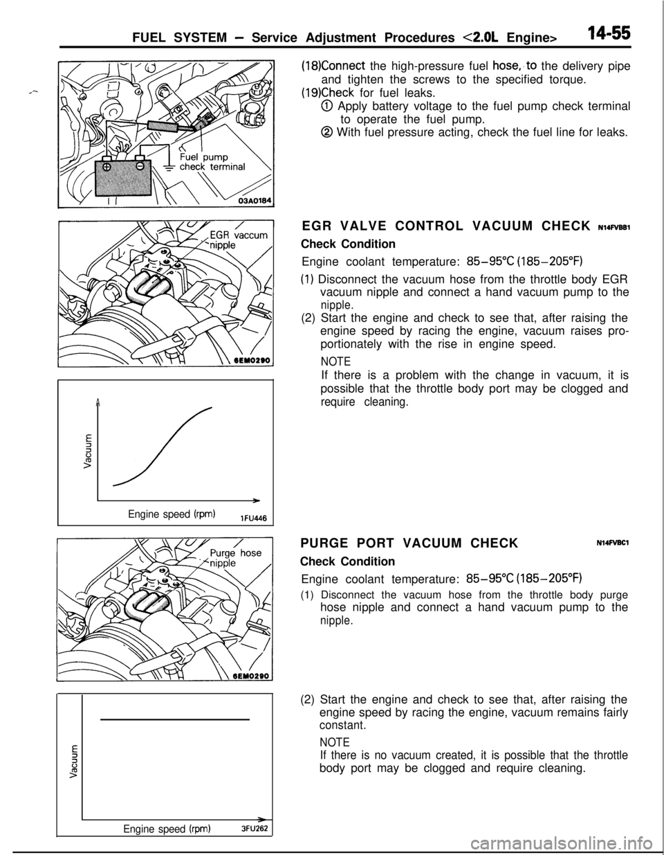
Engine speed (rpm)lFU4l6EGR VALVE CONTROL VACUUM CHECK
NlQFVBBlCheck Condition
Engine coolant temperature:
85-95°C (185-205°F)
(1) Disconnect the vacuum hose from the throttle body EGR
vacuum nipple and connect a hand vacuum pump to the
nipple.(2) Start the engine and check to see that, after raising the
engine speed by racing the engine, vacuum raises pro-
portionately with the rise in engine speed.
NOTEIf there is a problem with the change in vacuum, it is
possible that the throttle body port may be clogged and
require cleaning.PURGE PORT VACUUM CHECK
Check Condition
N14FVBClEngine coolant temperature:
85-95°C (185-205°F)
(1) Disconnect the vacuum hose from the throttle body purge
hose nipple and connect a hand vacuum pump to the
nipple.
Engine speed (rpm)3FU262(2) Start the engine and check to see that, after raising the
engine speed by racing the engine, vacuum remains fairly
constant.
NOTE
If there is no vacuum created, it is possible that the throttlebody port may be clogged and require cleaning.
Page 516 of 1216

14-62FUEL SYSTEM - MPI System Inspection <1.8L Engine>
INTAKE AIR TEMPERATURE SENSORNlmNABAir flow sensor
side connectorINSPECTION(1) Disconnect the air flow sensor connectors.
(2) Measure resistance between terminals
@ and @.
6FUO622
Temperature “C PF)Resistance kR
0 (32)6.0
20(68)2.780(176)
0.4(3) Measure resistance while heating the sensor using a hair
drier.
Temperature “C (“F)Resistance kfi
HigherSmaller(4) If the value deviates from the standard value or the
resistance remains unchanged, replace the air flow sensor
assembly.
ENGINE COOLANT TEMPERATURE SENSOR
NWQABE
INSPECTION(1) Remove engine coolant temperature sensor from the
intake manifold.
(2) With temperature sensing portion of engine
cool?nttemperature sensor immersed in hot water, check resist-
ance.16R1251
Temperature “C (“F)Resi’stance kQ
0 (32)5.920(68)
2.5
40 (104)2.7
80(176)0.3(3) If the resistance deviates from the standard value greatly,
replace the sensor.
INSTALLATION(1) Apply specified sealant to threaded portion and tighten to
specified torque.
Specified sealant: MOPAR Part No.4318034
or equivalent
Specified torque: 20
- 40 Nm (15 - 29 ftlbs.)(2) Fasten harness connectors securely.
Page 517 of 1216

FUEL SYSTEM - MPI Svstem Inspection <1.8L Engine>18-63
Throttle position sensor
Groundoutput
Sensorpower
SUPPlY(5V)
1 FUO507
6FU1244Motor
Dosition sensor connector
(motor ‘side, front view)
T
6FU1247Motor position sensor
connector(motor side, front view)
6FU1252
THROITLE POSITION SENSOR
INSPECTION
Nl4OBBKa(1) Disconnect the throttle position sensor connector.
(2) Measure resistance between terminal
@I (sensor ground)
and terminal
@ (sensor power).
Standard value: 3.5-6.5
kGI(3) Connect a pointer type ohmmeter between terminal
@(sensor ground) and terminal
@ (sensor output).
(4) Operate the throttle valve slowly from the idle position to
the full open position and check that the resistance changessmoothly in proportion with the throttle valve opening
angle.(5) If the resistance is out of specification, or fails to change
smoothly, replace the throttle position sensor.
Throttle position sensor installation torque:
1.5
- 2.5 Nm (1.1 - 1.6 ftlbs.)
IDLE POSITION SWITCH
INSPECTION
N14QKADa(1) Disconnect the connectors of the motor position sensor.
(2) Check the continuity between terminal
@ and the body
ground.
IAccelerator pedalIContinuityI
DepressedINon-conductive (@J fl)I
ReleasedIConductive (0 fl)I(3) If defective, replace the idle speed control servo assembly.
MOTOR POSITION SENSOR
INSPECTION
N140lAJ(1) Disconnect the motor position sensor connector.
(2) Measure the resistance between terminals
@ and 0.Standard value: 4
- 6 kfi
Page 518 of 1216

14-64FUEL SYSTEM -MPI System Inspection <1.8L Engine>
Idle speed controlservo connector
6FU098t(3) Disconnect the idle speed control servo connector.
(4) Connect DC
6V between terminals @) and @ of the idle
speed control servo connector, and then measure the
resistance between terminals
@ and @ of the motor
position sensor connector when the idle speed control
servo is activated (caused to expand and contract).
Standard value: Smooth increase/decrease in accord-
ance with extension and retraction of
idle speed control servo plunger.
Caution
Apply only a 6V DC or lower voltage. Application of
higher voltage could cause locking of the servo gears.
(5) If there is a deviation from the standard value, or if the
change is not smooth, replace the idle speed control servo
assembly.
OXYGEN SENSORN14QDBAb
INSPECTIONCaution
1. Before checking, warm up the engine until engine
coolant temperature reaches 85 to
95°C (185 to 205°F).2. Use an accurate digital voltmeter.
(1) Disconnect the oxygen sensor connector and connect a
voltmeter to the oxygen sensor connector.
(2) While repeating engine racing, measure the oxygen sensor
output voltage.
EngineOxygen sensor
output voltageRemarks
Race0.6- 1 .OVMake air-fuel mixture
rich by accelerator
operation
NOTEFor removal and installation of the oxygen sensor, refer
toGROUP 11
- Exhaust Manifold.
Oxygen sensor installation torque:
40
-50 Nm (30 - 36 klbs.)
EGR TEMPERATURE SENSOR
- Exhaust Gas Recirculation System.
VEHICLE SPEED SENSORN14QEEBaRefer to GROUP 8
- Meters and Gauges.
AIR CONDITIONER SWITCHRefer to GROUP 8
- Column Switch.
N14QQABa