1991 MITSUBISHI ECLIPSE brake sensor
[x] Cancel search: brake sensorPage 695 of 1216

TRANSAXLE ’
MANUAL AND AUTOMATICCONTENTS
;-AUTOMATICTRANSAXLE
.....................................................137ANNULUS GEAR AND TRANSFER DRIVE GEAR SET (F4A22)..........315ANNULUS GEAR AND TRANSFER DRIVE GEAR SET(F4A33.W4A33)...........................................................................................317CENTERDIFFERENTIAL(W4A33).............................................................329DIFFERENTIAL............................................................................................319ENDCLUTCHASSEMBLY.........................................................................309EXTENSIONHOUSINGASSEMBLY(W4A33).........................................337FRONTCLUTCHASSEMBLY....................................................................302FRONTOUTPUTSHAFT(W4A33)...........................................................332GENERALINFORMATION.........................................................................137KICKDOWNSERVO....................................................................................322LOW-REVERSEBRAKE..............................................................................323OILPUMP...................................................................................................299PLANETARYGEARSET............................................................................311PLANETARYGEARSET............................................................................313REARCLUTCHASSEMBLY(F4A22)........................................................304REARCLUTCHASSEMBLY(FQA33sW4A33)............................................307SERVICEADJUSTMENTPROCEDURES..................................................Drive
Shaft,OilSealsReplacement....................................................;;;
InhibitorSwtchAdjustment................................................................21 1KeyInterlockMechanismCheck.....................................................KrckdownServoAdjustment..................................zii..............................
LinePressureAdjustment...................................................................213
ReducingPressureAdjustment.........................................................214Selector Lever Operation Check........................................................210ShiftLockMechanismCheck...............................................................21 1SpeedometerCableReplacement.........................................................Throttle-posltipn Sensor Adjustment.................................................z2:
TransaxleFluIdLevelInspectIon......................................................209
TransaxleFluidReplacement.............................................................209
SPECIALTOOLS.........................................................................................SPECIFICATIONS........................................................................................;“5”9
GeneralSpeclficatlons..................................................................1%Lubricants..................................................................................Sealants and Adhesives..............................................................izi
Serwce Speclflcatlons..................................................159...............Spacer andSnapRing.,.,.............................................................Spacer Set..................................................................1::Torque Speclflcatlons...........................................166Valve Body Spring Identification Chart.....................
.................160
SPEEDOMETERGEARASSEMBLY..........................................................TRANSAXLEASSEMBLY(WA22)............................................................zTRANSAXLE
ASSEMBLY(F4A33.W4A33)................................................TRANSAXLECONTROL.............................................................................;;;TRANSAXLE
OILCOOLER........................................................................TRANSFER..................................................................................................fg
TRANSFERASSEMBLY.............................................................................333TRANSFERCASEADAPTERSUBASSEMBLY(W4A33).......................339TRANSFER CASE SUB ASSEMBLY (W4A33)341TRANSFER SHAFT (F4A33)TROUBLESHOOTING..................................................................................................................................................................................................f;;VALVE
BODY.............................................................................................324
MANUAL TRANSAXLE
5TH-SPEEDSYNCHRONIZERASSEMBLY...............................................42GENERALINFORMATION.........................................................................2.-.INPUTfj,-,A,TASSEMBLY
INTERMEDIATE GEAR ASSEMBLY..........................................................56OUTPUT
SHAFT ASSEMBLY....................................................................61SERVICEADJUSTMENTPROCEDURES..................................................DriveShaftOilSealsReplacement......................................................;;Speedometer Cable Replacement.........................................................
Transaxle Oil Level
InspectIon..............................................................‘liTransaxle Oil Replacement....................................................................
I3
SHIFTLEVERASSEMBLY.........................................................................SHIFTRAILSANDFORKS........................................................................g
SPECIALTOOLS.........................................................................................SPECIFICATIONS........................................................................................1:
General Specifications5Lubricants..........................................................................................................................................................................10Sealants and Adhesives
Service Specifications
....................................................................................................................................................1:Snap Ring (for Adjustment) and Spacer...............................................
Torque Specifications.............................................................................
i
SPEEDOMETERGEARASSEMBLY..........................................................TRANS&G.E................................................................................................zTRANSAXLEA!jSEMBLY
TROUBLESHOOTING..................................................................................12
MANUAL TRANSAXLE
CENTERDIFFERENTIAL.............................................................................103CLUTCHHOUSINGASSEMBLY...............................................................DRIVE BEVEL GEAR ASSEMBLY;g
...... .......................................................DRIVENBEVELGEARASSEMBLY...................................a......................EXTENSIONHOUSINGASSEMBLY.........................................................;g
5Tf.jSPEEDSYNCHRONIZERASSEMBLY...............................................101
FRONTDlFFERENTlAL...............................................................................106
FRONTOUTPUTSHAFTASSEMBLY......................................................106
GENERALI~~~~MATN)N...............................................................,.,.......66INPUTSHAFTASSEMBLY........................................................................l~ER,“,EDlATEGEARASSMBLY..........................................................;;i
SERVICEADJUSTMENTPROCEDURES..................................................Drive Shaft Oil Seals Replacement......................................................;;Speedometer Cable Replacement.........................................................
Transaxle
Ojl Level lnspectlon..............................................................;l
Transaxle 011 R~pb33ment....................................................................79Transfer
OilSealReplacement.............................................................80
SHIFTLEVERASSEMBLY.........................................................................SHIFTRAILASSEMBLY............................................................................,z
SPECIALTOOLS.........................................................................................76
SPECIFICATIONS........................................................................................6g
GeneralSpecifications...........................................................................6g
Lubricants...............................................................................................75
SealantsandAdhesives........................................................................76
ServiceSpecifications............................................................................6gSnap Ring (for Adjustment) and Spacer...............................................7 o
TorqueSpecifications.............................................................................74
SPEEDOMETERGEARASSEMBLY..........................................................TRANSAXLE................................................................................................1:TRANSAXLEASSEMBLY...........................................................................86TRANSAXLE
CONTROL
.............................................................................TRANSFER...............................................................................................
g.._TRANSFERA!333lBLY.............................................................................,24
TRANSFERCASEADAPTERSUBASSEMBLY.......................................131TRANSFERCASESUBASSEMBLY.........................................................TR,,UBLES,,OO,,NG..................................................................................1;;
Page 869 of 1216

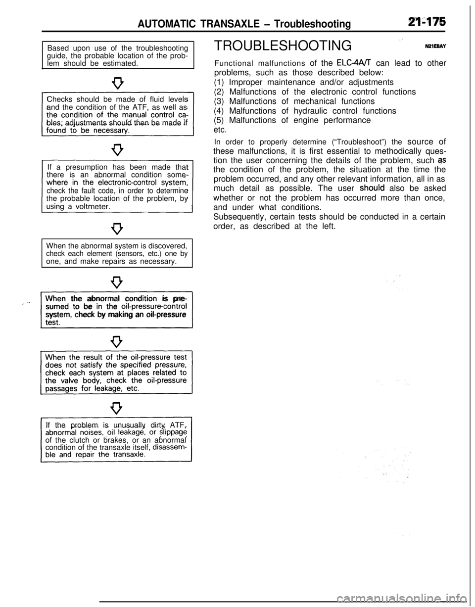
AUTOMATIC TRANSAXLE - TroubleshootingBased upon use of the troubleshooting
guide, the probable location of the prob-
lem should be estimated.
Checks should be made of fluid levels
and the condition of the ATF, as well as
bles; adjustments should then be made if
If a presumption has been made that
there is an abnormal condition some-
check the fault code, in order to determinethe probable location of the problem, by
When the abnormal system is discovered,
check each element (sensors, etc.) one byone, and make repairs as necessary.
“~^II_When the abnormal condition is pre-
sumed to be in the
orI-pressure-controlsystem, check by making an oil-pressure
If the problem is unusually dirty ATF,
of the clutch or brakes, or an abnormal
condition of the transaxle itself,
disassem-TROUBLESHOOTING
”N21EeAYFunctional malfunctions of the ELC4A/T can lead to other
problems, such as those described below:
(1) Improper maintenance and/or adjustments
(2) Malfunctions of the electronic control functions
(3) Malfunctions of mechanical functions
(4) Malfunctions of hydraulic control functions
(5) Malfunctions of engine performance
etc.In order to properly determine (“Troubleshoot”) the source of
these malfunctions, it is first essential to methodically ques-
tion the user concerning the details of the problem, such qs
the condition of the problem, the situation at the time the
problem occurred, and any other relevant information, all in as
much detail as possible. The user
shoutd also be asked
whether or not the problem has occurred more than once,
and under what conditions.
Subsequently, certain tests should be conducted in a certain
order, as described at the left.
Page 908 of 1216

21-214AUTOMATIC TRANSAXLE - Service Adjustment Procedures
'50157
F4
1
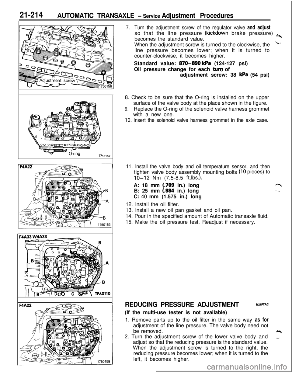
7.Turn the adjustment screw of the regulator valve and adjustso that the line pressure
(kickdown brake pressure) a,becomes the standard value.
When the adjustment screw is turned to the clockwise, the
Lline pressure becomes lower; when it is turned to
counter-clockwise, it becomes higher.
Standard value:
870-890 kPa (124-127 psi)
Oil pressure change for each turq of
adjustment screw: 38
kPa (54 psi)
8. Check to be sure that the O-ring is installed on the upper
surface of the valve body at the place shown in the figure.
9.Replace the O-ring of the solenoid valve harness grommet
with a new one.
10. Insert the solenoid valve harness grommet in the axle case.
11. Install the valve body and oil temperature sensor, and then
(IO pieces) to
tighten valve body assembly mounting bolts
IO-12 Nm (7.5-8.5 ft.lbs.).A: 18 mm
(.709 in.) long
B: 25 mm
(.984 in.) long
C: 40 mm (1.575 in.) long
12. Install the oil filter.
13. Install a new oil pan gasket and oil pan.
14. Pour in the specified amount of Automatic transaxle fluid.
15. Make the oil pressure test. Readjust if necessary.
+-t
--,,
REDUCING PRESSURE ADJUSTMENTNZlFTAC(If the multi-use tester is not available)
1. Remove parts up to the oil filter in the same way as for
adjustment of the line pressure. The valve body need not
be removed.
+%2. Turn the adjustment screw of the lower valve body and_adjust so that the reducing pressure is the standard value.
When the adjustment screw is turned to the right, the
reducing pressure becomes lower; when it is turned to the
left, it becomes higher.
Page 951 of 1216

AUTOMATIC TRANSAXLE - Transaxle Assembly
7750157
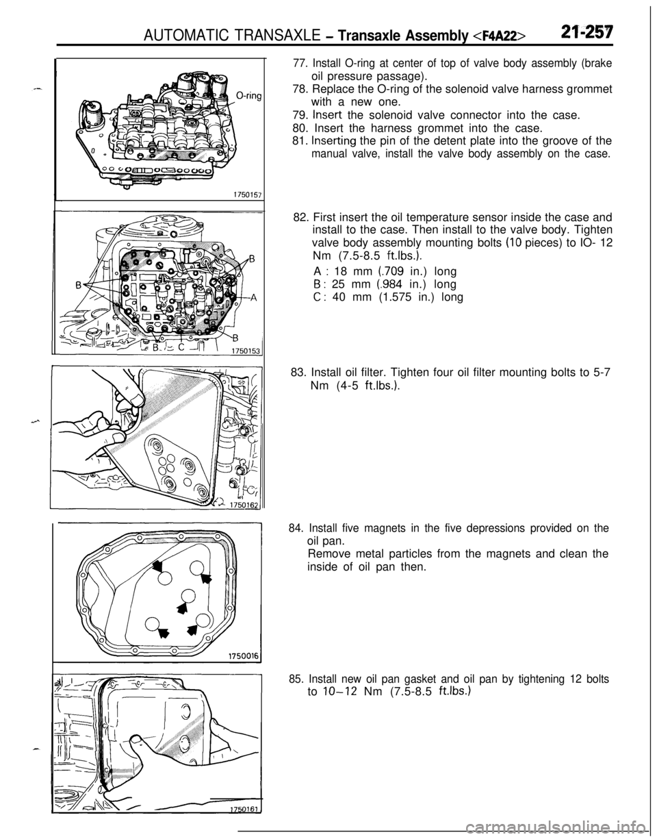
77. Install O-ring at center of top of valve body assembly (brakeoil pressure passage).
78. Replace the O-ring of the solenoid valve harness grommet
with a new one.
79.
Insert the solenoid valve connector into the case.
80. Insert the harness grommet into the case.
81.
Inserting the pin of the detent plate into the groove of the
manual valve, install the valve body assembly on the case.82. First insert the oil temperature sensor inside the case and
install to the case. Then install to the valve body. Tighten
valve body assembly mounting bolts
(IO pieces) to IO- 12
Nm (7.5-8.5
ft.lbs.).A
: 18 mm (709 in.) long
6 : 25 mm (.984 in.) long
C : 40 mm (1.575 in.) long
83. Install oil filter. Tighten four oil filter mounting bolts to 5-7
Nm (4-5
ft.lbs.1.
84. Install five magnets in the five depressions provided on theoil pan.
Remove metal particles from the magnets and clean the
inside of oil pan then.
85. Install new oil pan gasket and oil pan by tightening 12 boltsto
lo-12 Nm (7.5-8.5 ft.lbs.1
Page 960 of 1216

21-266 AUTOMATIC TRANSAXLE -Transaxle Assembly
DISASSEMBLY AND REASSEMBLY
20.Pressure pla?e21.Brake disc22.Brake plate23.Reaction plate
24. Reverse sun gear25. Thrust bearing
#826. Thrust race
#9---
1.Torque converter2.Oil pump assembly3.Gasket4.Thrust washer #I5. Front clutch assembly
6. Thrust race #37. Thrust bearing #48. Thrust washer #227. l-or-ward sun gear
9. Rear clutch assembly28. Planetary carrier assembly
10. Thrust bearing #529.Thrust bearing#I0
11. Rear clutch hub30.Output flange
12. Thrust race
#631. Oil level gauge
13. Thrust bearing #732. Oil filler tube14.Kickdownband33.
Snap ring15.Kickdowndrum34. Kickdown servo switch16.Snap ring35.Snap ring
Ii524
23
TFA0405’36.
Kickdown servo piston
37.Spring
38.Anchor rod
39.Detent assembly40. Manual control shaft
41. Parking roller support
42.Oilpan43.Gasket44. Oil temperature sensor
45.Oil screen
46. Valve body assembly
47. Manual control lever
48.Inhibitor switch49. End clutch shaft50.Bearing retainer51.Thrust bearing #I152. End clutch hub53.Thrust washer
54. End clutch assembly
55.O-ring
56. End clutch cover
57.Pulse generator58:Lock bolt59.Idler shaft60.Idlergear61.Spacer
62.Gasket
Page 962 of 1216

21-268 AUTOMATIC TRANSAXLE -Transaxle Assembly
TFA0409
1.Torque converter2.Oil pump assembly3.Gasket4.Thrust washer #I5.Front clutch assembly
6. Thrust race #37.Thrust bearing #48. Thrust washer
#29.Rear clutch assembly
10. Thrust bearing #511.Rear clutch hub12.Thrust race #613.Thrust bearing #714.Kickdown band15.Kickdown drum16.Snap ring
17.Center support18.Wave spring19.Return spring20.Pressure plate21.Brake disc22.Brake plate23.Reaction plate24.Reverse sun gear25. Thrust bearing #826.Thrust race #927. Forward sun gear
28.Planetary carrier assembly29. Thrust bearing #IO30.Output flange31.Oil level gauge32.Oil filler tube33.Snap ring34.Kickdown servo switch35.
Snap ring36.
Kickdown servo piston
37.Spring38.Anchor rod39.Detent assembly40. Manual control shaft
41. Parking roller support
42.Oilpan43.Gasket44.Oil temperature sensor45.Oil screen46.Valve body assembly47.Manual control lever48.Inhibitor switch49.End clutch shaft50.Bearing retainer51.Thrust bearing #I 1
52. End clutch hub
53.Thrust washer54. End clutch assembly55.O-ring
56. End clutch cover
57.Pulse generator58.Lock bolt59.Idler shaft60.Idler gear61.Spacer
62.Gasket