Page 84 of 1216
2-36FRONT SUSPENSION - Lower Arm
Lips
/IDust
cover
12R0487BALL JOINT DUST COVER REPLACEMENT
NOZNEAF
(1) Remove the dust cover.
(2) Apply multipurpose grease to the lip and inside of the dust
7
cover.Grease: MOPAR Multi-mileage Lubricant
Part No.2525035 or equivalent
(3) Drive in the dust cover with special tool until it is fully
seated.SERVICE POINTS OF INSTALLATION
NOZNFAL5. INSTALLATION OF STABILIZER LINK MOUNTING
NUTS
Using a wrench or similar tool to secure the ball studs at
Tboth ends of the stabilizer link, tighten the mounting nuts.
1. INSTALLATION OF STABILIZER BAR MOUNTING NUT
Tighten the nut on the stabilizer bar bolt to the specified
distance.Standard value:
Protruding length of stabilizer bar
.M”mounting bolt16-18 mm
(.63-.70 in.) .
Page 85 of 1216
FRONT SUSPENSION - Stabilizer Bar2-37
STABILIZER BAR
-I*_ REMOVAL AND INSTALLATION
. .Removal steps
1. Self-locking nut
4*2. Front exhaust pipez’
gitket5: Center member rear installation bolt
l 4 6.Stabilizer bar mounting nut
7.Stabilizer bar mounting bolt
8.J&~;~cups and bushing
Stabilizer bar bracket mounting bolt
Sg:asAi;r bar bracket
Stabilizer bar
9.
l41::
14.4*15.22-29
ft.lbs.
30-40 Nm
22-29 ft.lbs.2
12A0555
NO2TAANOTE
(I) Reverse the removal procedures to reinstall.(2) 4* : Refer to “Service Points of Removal”.(3) l 4 : Refer to “Service Points of Installation”.(4) q : Non-reusable parts12*0229
Page 86 of 1216
2-38FRONT SUSPENSION - Stabilizer Bar
type>
40-60 Nm
29-43 fLlb52-72
klbs.
Removal steps
4*
1, Self-locking nut
2. Front exhaust pipe
3. Gasket30-:O Nm
22-29 ftlbs.
V2
30-40 Nm
22-29 ft.lbs.
4.Stay
5. Center member rear installation bolt
4e l 4 10. Stabilizer link mounting nutII. Stabilizer link12. Stabilizer bar bracket mounting bolt
l 413.Stabilizerbarbracket
14.Bushing4*15. Stabilizer bar
c- r35-45
25-33
ft.lbs. 10
NOTE(I) Reverse the removal procedures to reinstall.(2) 4e : Refer to “Service Points of Removal”.(3) l + : Refer to “Service Points of Installation”(4) m : Non-reusable parts12A0228
Page 87 of 1216
FRONT SUSPENSION - Stabilizer Bar2-39SERVICE POINTS OF REMOVAL
NOZTBAFa2. REMOVAL OF FRONT EXHAUST PIPE
After disconnection of the front exhaust pipe assembly and
the exhaust manifold, use wire, etc. to hang the front
exhaust pipe down.
Caution
There is danger of damage to the interior if the flexible
joint is bent very much. Do not bend it more than
shown in the figure.
10. REMOVAL OF STABILIZER LINK MOUNTING NUT
Using a wrench or similar tool to secure the ball studs at
both ends of the stabilizer link, remove the mounting nuts.
15. REMOVAL OF STABILIZER BAR
(1) Pull out both ends of the stabilizer bar to the rear of the
drive shaft.
(2) Move the right stabilizer bar until the end of the
stabilizer bar clears the lower arm.
(3) With the end that has cleared the lower arm, pull out
the stabilizer bar diagonally.
Page 88 of 1216

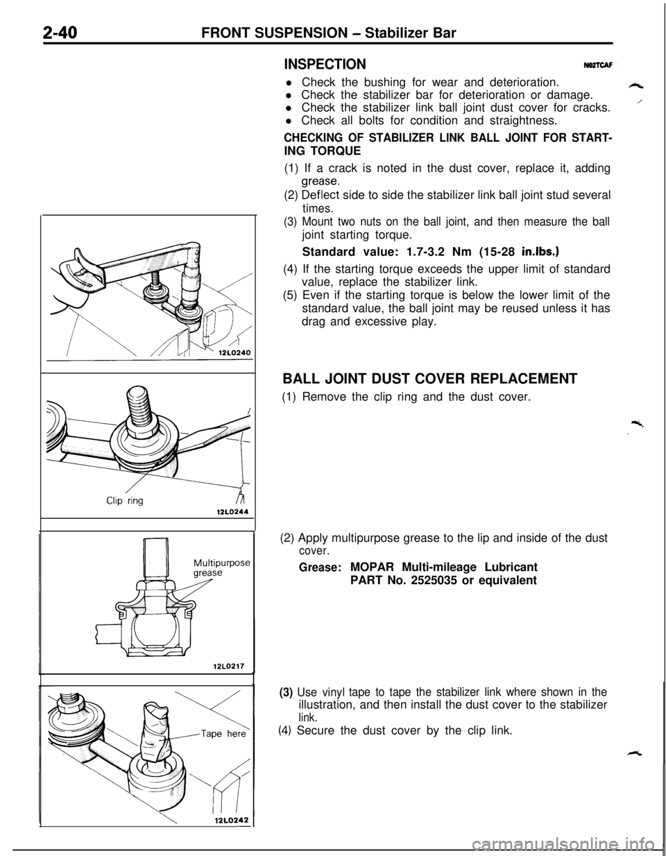
12LO244Z-40FRONT SUSPENSION - Stabilizer Bar
INSPECTIONNO2TCAFl Check the bushing for wear and deterioration.
l Check the stabilizer bar for deterioration or damage.
l Check the stabilizer link ball joint dust cover for cracks.
l Check all bolts for condition and straightness.
CHECKING OF STABILIZER LINK BALL JOINT FOR START-ING TORQUE
(1) If a crack is noted in the dust cover, replace it, adding
(2)
~~f~~~t side to side the stabilizer link ball joint stud several
times.
(3) Mount two nuts on the ball joint, and then measure the balljoint starting torque.
Standard value: 1.7-3.2 Nm (15-28
in.lbs.)(4) If the starting torque exceeds the upper limit of standard
value, replace the stabilizer link.
(5) Even if the starting torque is below the lower limit of the
standard value, the ball joint may be reused unless it has
drag and excessive play.
12LO217
12LQ242-BALL JOINT DUST COVER REPLACEMENT
(1) Remove the clip ring and the dust cover.
(2) Apply multipurpose grease to the lip and inside of the dust
cover.
Grease:MOPAR Multi-mileage Lubricant
PART No. 2525035 or equivalent
(3) Use vinyltape to tape the stabilizer link where shown in theillustration, and then install the dust cover to the stabilizer
link.
(4.) Secure the dust cover by the clip link.
rt
/
Page 89 of 1216
FRONT SUSPENSION - Stabilizer Bar241
3 *!-Marking
A I I\/\ \lZAOOOESERVICE POINTS OF INSTALLATION
NO2lDAK13. INSTALLATION OF STABILIZER BAR
FRACKET(1) Temporarily tighten the stabilizer bar bracket:
’(2) Align the bushing end with the marked part of the
stabilizer bar, and then fully tighten the stabilizer. bar
bracket.10. INSTALLATION OF STABILIZER LINK MOUNTING NUT
Using a wrench or similar tool to secure the ball studs at
both ends of the stabilizer
link, tighten the mounting nuts.
6. INSTALLATION OF STABILIZER BAR MOUNTING NUT
Tighten the nut on the stabilizer bar bolt to the specified
distance.Standard value:
Protruding length of stabilizer bar
mounting bolt16-18 mm
(.63-.70 in.)
Page 90 of 1216
Page 91 of 1216
FRONT SUSPENSION - Stabilizer Bar2-43SERVICE POINTS OF REMOVAL
NOZlBAG4. REMOVAL OF STABILIZER LINK MOUNTING NUTS
Using a wrench or similar tool to secure the ball studs at
both ends of the stabilizer link, remove tfie mounting nuts,
19. REMOVAL OF STABILIZER BAR
(1) Disconnect the coupling of the knuckle and lower arm
at the right side.
(2) Pull out the left side stabilizer bar edge, pulling it out
between the drive shaft and lower arm.
(3) Pull out the right side stabilizer bar edge, pulling it out
from below the lower arm.
INSPECTIONRefer to
P.2-40.
NOZTCAHBALL JOINT DUST COVER
REPLACEMENTNomDRefer to
P.2-40.SERVICE POINTS OF INSTALLATION
NOZTDAN7. INSTALLATION OF STABILIZER BAR
BRACKET!4. STABILIZER LINK INSTALLATION NUT
Refer to
P.2-41.