Page 675 of 1216
--STEERING - Manual Steering Gear Boxm-2.7
13AO175
Grease
136007(1184-186 mm
(7.24-7.32
in.)
13ElW8. INSTALLATION OF TIE-ROD
After installing tie-rod to rack, fold tab washer
end, (2locations) to tie-rod notch.
’.
.‘6. APPLICATION OF GREASE TO BELLOW
Pack tie rod bellows lock groove with specified grease.
Specified grease: Silicone grease
3.INSTALLATION OF DUST COVER
(1) Pack dust cover interior and lip with multipurpose grease.Grease: MOPAR Multi-mileage Lubricant Part
No. 2525035 or equivalent
(2) Apply specified sealant to dust cover.
Specified sealant:
3M ATD, Part No.8663 or equiva-
lent
(3) Using the special tool, press dust cover to tie-rod end.
2. INSTALLATION OF TIE-ROD END
Screw in tie-rod end to have its right and left ‘length as
illustrated. Lock with locking nut.
Page 682 of 1216

19-34STEERING - Power Steering Gear Box
Guide
/Oil seal
Back-up washer13A0181
roller
13R0380
O-ring
13R037E
V&t hole
13K583-SERVICE POINTS OF REASSEMBLY
NlSPHAV
34. INSTALLATION OF BACK-UP WASHER133. OIL SEAL
(1) Apply a coating of the specified fluid to the outside of the
oil seal.
Specified fluid: MOPAR ATF PLUS (Automatic Trans-mission Fluid Type 7176)/Automatic
transmission fluid “DEXRON” or
“DEXRON II”
(2) Using a tool, press the back-up washer and the oil seal
into the rack housing to the specified position (where theupper surface of the press-in guide coincides with the
stepped part of the press-in tool).
32. INSTALLATION OF NEEDLE ROLLER BEARING
(1) Apply specified fluid to housing, bearing and oil seal
press fitting surface.
Specified fluid:MOPAR ATF PLUS (Automatic Trans-mission Fluid Type 7176)/Automatic
transmission fluid “DEXRON” or
“DEXRON II”
(2) Press fit needle roller bearing.
Caution
Press fit straight as valve housing is aluminium.
31. INSTALLATION OF BALL BEARING
Press fit ball bearing.28. INSTALLATION OF OIL SEAL/27. O-RING(I
1 Apply a coating of the specified fluid to the outside of the
oil seal and O-ring.
Specified fluid: MOPAR ATF PLUS (Automatic Trans-
mission Fluid Type 7176VAutomatictransmission fluid “DEXRON” or
“DEXRON II”
(2) Press fit oil seal until it touches rack bush end.
26. INSTALLATION OF RACK ASSEMBLY
(1) Apply a coating of multipurpose grease to the rack teeth
face.Grease: MOPAR Multi-mileage Lubricant PartNo.2525035 or equivalent
CautionDo not close the vent hole in the rack with grease.
Page 684 of 1216

19-36STEERING - Power Steering Gear BoxMB991317
side
13A031fVinyl tape
APP~automatic
transmissionfluid
13POl44
IApprox. 1 mm
(Approx. ,040 in.)i, Tool
’ 13POO76
13A014:
End plug
Sealant
13K,30II
I
IEnd plug\ ,I
NOTE
Because the seal rings expand at the time of installation,use the special tool to compress the seal rings so that
-they are well seated.
L
(2) Apply multipurpose grease to pinion gear and housing
bearing.Grease: MOPAR Multi-mileage Lubricant
PartNo.2525035 or equivalent
(3) Wrap vinyl tape around the serrated part so that the oil
seal won’t be damaged when the pinion
and valveassembly is installed to the valve housing.
(4) Mount the pinion and valve assembly to the valve
housing.
18. INSTALLATION OF OIL SEAL
Using a tool, press the oil seal into the valve housing.
CautionIn order to eliminate a seal malfunction at the valve
-
housing alignment surface, the upper surface of -the oilseal should project outward
approximatelv 1 mm t.040in.) from the housing edge surface.
‘, I
16. INSTALLATION OF RACK SUPPORTApply multipurpose grease to the rack support surface in
contact with the rack bar.
Grease: MOPARMulti-mileage
LubricantPartNo. 2525035 or equivalent
14. INSTALLATION OF RACK SUPPORT COVER
Apply semi-drying sealant to rack support cover screw. Locktemporarily with locking nut.
11. INSTALLATION OF END PLUG
(1) Apply the specified sealant to the threaded part of the
end plug.
Specified sealant:
3M ATD Part No.6663 or equiva-
lent
rL-
(2) Secure the threaded portion of the end plug at two._places by using a punch.
Page 685 of 1216

STEERING - Power Steering Gear Box
13A017EI
\Silicon grease
Lip
Sealant131564-r-MB990776-A
13A0259l ADJUSTMENT OF TOTAL PINION TORQUE
(1) Position rack at its center. With special tool, tighten racksupport cover to 15 Nm (11
ftlbs.).(2) In neutral position, rotate pinion shaft clockwise one
turn/4-6 seconds with special tool. Return rack, support
cover
30°-60° and adjust torque to the stanoard,vaiue.Standard value:
0.6-l .3 Nm (5-l 1 in.lbs.1
Caution1. When adjusting, set the standard value at its
highest value.2. Assure no ratcheting or catching when operating
rack towards the shaft direction.
NOTEWhen it cannot be adjusted within the specified return
angle, check rack support cover components or replace.
(3) After adjusting, lock rack support cover with locking nut.8. INSTALLATION OF TIE ROD
After installing tie rod to rack, fold tab washe;, end (2
locations) to tie rod notch.
‘*,t, \
\6. APPLICATION OF GREASE TO BELLOWS
Pack tie rod bellows lock groove with specified grease.
Specified grease: Silicone grease3. INSTALLATION OF DUST COVER
(1) Pack dust cover interior and lip with multipurpose grease.Grease: MOPAR Multi-mileage Lubricant Part
No. 2525035 or equivalent
(2) Apply specified sealant to dust cover.
Specified sealant: 3M ATD Part
No.8663 or equiva-
lent
(3) Using the spcial tool, press dust cover to tie rod end.
Page 713 of 1216

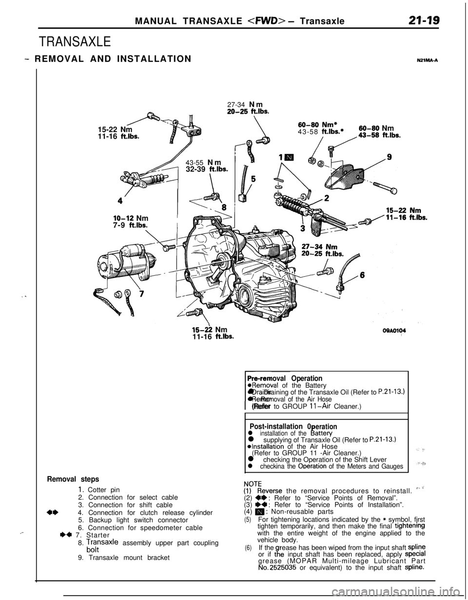
MANUAL TRANSAXLE - Transaxle21-19
TRANSAXLE
- REMOVAL AND INSTALLATIONNZlMA-A
. .
,-27-34 Nm
20-25 ft.lbs.15-22 Nm
11-16
ft.lbs.43-55 Nm
32-39
ft.lbs.
\
60-80 Nm*43-58 ft.lbs.*60-80 Nm
/da-,, ft.lbs.
lo-12 NmI7-9
ft.lbs.I
15-2: Nm
11-16 ft.lbs.OOAOl~4
Pre-removal Operation@Removal of the Battery
rl Draining of the Transaxle Oil (Refer to
P.21-13.)l Removal of the Air Hose(Refer to GROUP 11-Air Cleaner.)
Post-installation 0erationl installation of theI!attery
l supplying of Transaxle Oil (Refer to P.21-13.)*Installation of the Air Hose
(Refer to GROUP 11 -Air Cleaner.)
l checking the Operation of the Shift Lever
l checkina the Ooeration of the Meters and Gauges
Removal steps
1. Cotter pin
2. Connection for select cable
3. Connection for shift cable
4*4. Connection for clutch release cylinder
5. Backup light switch connector
6. Connection for speedometer cable
I)* 7. Starter
8.
Lfrsaxle assembly upper part coupling
9. Transaxle mount bracket
ZKeverse the removal procedures to reinstall. ” ’(2) W : Refer to “Service Points of Removal”.
(3) ~~ : Refer to “Service Points of Installation”.
(4) m : Non-reusable parts
(5)For tightening locations indicated by the * symbol, fjrst
tighten temporarily, and then make the final tightenrngwith the entire weight of the engine applied to the
vehicle body.
(6)If therease has been wiped from the input shaft spline
or if taeinput shaft has been replaced, apply specralgrease (MOPAR Multi-mileage Lubricant Part
No.2525035 or equivalent) to the input shaft Spline.
Page 776 of 1216

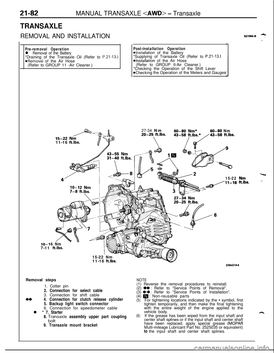
21-82MANUAL TRANSAXLE - Transaxle
TRANSAXLE
REMOVAL AND INSTALLATION
Pre-removal Operationl Removal of the Battery*Draining of the Transaxle Oil (Refer to P.Zl-13.)
@Removal of the Air Hose
(Refer to GROUP 11 -Air Cleaner.)IO-1
7-1111-16
ftlbs.
Post-installation Operation@Installation of the Battery
*Supplying of Transaxle Oil (Refer to P.21-13.)*Installation of the Air Hose
(Refer to GROUP II-Air Cleaner.)
*Checking the Operation of the Shift Lever
@Checking the Operation of the Meters and Gauges
27-34 Nm
60-60 Nm*60-80 Nm20-25 ft.lbs.
\
43-58/t.,b~43-58 ft.lbs.
15-22
6 Nm
ftlbs.
15-22 Nm
vt11-16
ft.lbs.Removal steps
1. Cotter pin
2. Connection for select cable
3. Connection for shift cable
*I)4. Connection for clutch release cylinder
5. Backup light switch connector
6. Connection for speedometer cable
l * 7. Starter
8.
A;;saxle assembly upper part coupling
9. Transaxle mount bracket
NZlMA-B -
,“rr,s.
09AOl44
NOTE(1) Reverse the removal procedures to reinstall.
(2)
+e : Refer to “Service Points of Removal”.
(3) I)+ : Refer to “Service Points of Installation”.
(4) m : Non-reusable parts(5)For tightening locations indicated by the * symbol, first
tighten temporarily, and then make the final tightening
with the entire weight of the engine applied to the
(6)vehicle body.
If the grease has been wiped from the input shaft and
center shaft splines or if the input shaft and center shaft
have been replaced, apply special grease
(MOPARMulti-mileage Lubricant Part No. 2525035 or equivalent)
to the input shaft and center shaft splines.
Page 779 of 1216

MANUAL TRANSAXLE - Transfer24-85
TRANSFER
--- REMOVAL AND INSTALLATION1NZlMAk
55-6040-43
Removal steps
1. Front exhaust pipe
2. Transfer assembly
NOTE(I) Reverse the removal procedures to reinstall.(2) +I) : Refer to “Service Points of Removal”.(3) q : Non-reusable parts.(4) If the grease has been wiped from the center shaft
spline or if the center shaft has been replaced, apply
special grease
(MOPAR Multi-mileage Lubricant PartNo.2525035 or equivalent) to the center shaft splrne.
ODA0027
B991193
oepoo44
SERVICE POINTS OF REMOVALNZlMBAU1. REMOVAL OF FRONT EXHAUST PIPE
Refer to GROUP 11 -Exhaust Pipe and Main Muffler.
2. REMOVAL OF TRANSFER ASSEMBLY
After moving the transfer assembly to the left and lowering,
the front side, then remove it from the propeller shaft.
Caution
1.Be cautious to avoid damaging the transfer oil seal
lip.2. The propeller shaft should be suspended so that it’
is not sharply bent.
3.Cover the transfer opening with the special tool to
prevent transaxle oil discharge and the entry of
foreign objects.
Page 862 of 1216

21-168AUTOMATIC TRANSAXLE - Specifications
-TRANSFER
ItemsNmCover mounting bolt
4-6
Driven bevel gear lock nut
140-160Extension housing mounting bolt
15-22Oil drain plug
30-35Oil filler plug
30-35Transfer case adapter mounting bolt
35-42
Transfer cover mounting bolt
35-42ft.lbs.
‘3-4
.
162-115 ‘i
‘11-1522-25
22-25
26-30
36-30
LUBRICANTSW1CD-C
ItemsSpecified lubricantQuantity
Transaxle fluidliters
(qts.) MOPAR ATF PLUS (Automatic transmission 6.1 (6.4) fluid type 7176) or Dia ATF SP7.6 (8.0)
or equivalent
:‘,Key interlock cableMOPAR Multi-mileage Lubricant PartAs required
Select lever assemblyNo. 2525035 or equivalent
Bushing, sleeve, spring,
pushbutton and lock cam
Drive shaft oil seal lipMOPAR ATF PLUS (Automatic transmission As required
fluid type 7176) or Dia ATF SP
or equivalent
SEALANTS AND ADHESIVESN2lcE-c
ItemsTransaxle case gasket
Bearing retainer screw boltsSpecified sealants and adhesives
Silicone grease
MOPAR Part
No.4318031 or MOPAR Part
No. 4318032 or equivalent
ItemsTransfer extension housing-Transfer adapter
Front bearing retainer bolts
Center differential flange bolts
Air breatherSpecified sealants and adhesives
MITSUBISHI Genuine Part
No.997740 or
equivalent::t;p,
MOPAR Part
No.4318031. or MOPAR ‘Part”’ ‘~’ “,“iNo.4318032 or equivalent’ ‘. :“’MOPAR Part No.4318025 or equivalent