Page 444 of 1216

INTeKE AND EXHAUST - Turbocharger
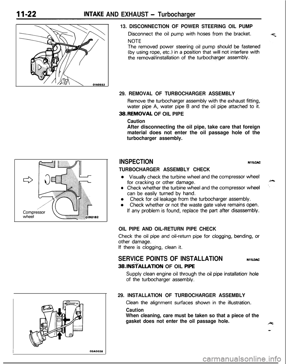
13. DISCONNECTION OF POWER STEERING OIL PUMP
Disconnect the oil pump with hoses from the bracket.
NOTE
The removed power steering oil pump should be fastened
(by using rope, etc.) in a position that will not interfere with
the removal/installation of the turbocharger assembly.
I05AOO26
29. REMOVAL OF TURBOCHARGER ASSEMBLY
Remove the turbocharger assembly with the exhaust fitting,water
pipe A, water pipe 6 and the oil pipe attached to it.3B.REMOVAL OF OIL PIPE
CautionAfter disconnecting the oil pipe, take care that foreign
material does not enter the oil passage hole of the
turbocharger assembly.
INSPECTIONNllLCAC
TURBOCHARGER ASSEMBLY CHECKl
Visually check the turbine wheel and the compressor wheelfor
cracking or other damage.
lCheck whether the turbine wheel and the compressor wheel
can be easily turned by hand.l
Check for oil leakage from the turbocharger assembly.l
Check whether or not the waste gate valve remains open.
If any problem is found, replace the part after disassembly.
OIL PIPE AND OIL-RETURN PIPE CHECK
Check the oil pipe and oil-return pipe for clogging, bending, or
other damage.
If there is clogging, clean it.
SERVICE POINTS OF INSTALLATIONNllLDAC-x_3SlNSTALLATlON OF OIL PlPE
Supply clean engine oil through the oil pipe installation hole
of the turbocharger assembly.
29. INSTALLATION OF TURBOCHARGER ASSEMBLY
Clean the alignment surfaces shown in the illustration.
Caution
When cleaning, care must be taken so that a piece of the
gasket does not enter the oil passage hole.
Page 450 of 1216

11-28INTAKE AND EXHAUST - Exhaust Manifold ~2.0~ DOHC Enoine (Turbo)>
EXHAUST MANIFOLD <2.0L DOHC Engine (Turbo)>
REMOVAL AND INSTALLATION
Pre-removal Operation*Draining Engine Coolant(Refer to GROUP O-Mainte-nance Service.)*Draining Engine Oil(Refer to GROUP O-Mainte-nance Service.)
Rennova1 steps
1.Condenser fan motor assemblyOxygen sensor connectorEngine oil level gauge guideO-ring
\30-40 Nm22-29 ft.lty3. & (
EJ\\=a-50 N
4 .ri29-38 ftk.
,
Post-installation Operation@Filling Engine Oil(Refer to GROUP O-Mainte-nance Service.)@Filling Engine Coolant(Refer to GROUP O-Mainte-nance Service.)NllNA-C
130 25-30 Nmd/18-22 ft.lbs.
;:4.
s5:7.
::10.Ii.12.13.14.15.
Connection for air intake hose
Connection for vacuum hoseConnection for vacuum hoseConnection for air hose AHeat protector AHeat protector 6Power steering oil pumpOil pump bracketSelf-locking nut
Engine hangerEve bolt
16. Gasket17. Connection for water hose
19IBWI 18. Connection for water pipe B19. Self-locking nut20.
Gasket
05Ao15421.
Exhaust manifold22. Exhaust manifold gasket23.
Ring24. Gasket
NOTE(1) Reverse the removal procedures to reinstall.(2) +, : Refer to “Service Points of Removal”.(3) l * : Refer to “Service Points of Installation”(4) m : Non-reusable parts
Page 451 of 1216
INTAKE AND EXHAUST - Exhaust Manifold II-28
OlAO552
05K55;,
SERVICE POINTS OF REMOVALNllNBAl
11. DISCONNECTION OF POWER STEERING OIL PUMP
:
Disconnect the oil pump with hoses from the bracket.
NOTE
The removed power steering oil pump should be fastened
(by using rope, etc.) in a position that will not interfere with
the removal/installation of the exhaust manifold.
lNSPECTlONNllNCALl
Check the following points; replace the part if a problem is
found.EXHAUST MANIFOLD
Check for damage or cracking of any part.EXHAUST MANIFOLD GASKET
Check for flaking or damage of the gasket.
SERVICE POINTS OF INSTALLATIONNllNQAG
18. INSTALLATION OF WATER PIPE (BI
Before installing to the water inlet pipe, apply machine oil to
the inner surface of the pipe flare.
Page 660 of 1216

19-12STEERING - Service Adjustment Procedures
Pressure ofWater pump
pulleyOlA0059Fluid fluctuation
While engine
runningWhile enginestopped13uo139
Return hoseVinyl hose
x ,3Ao,42-
V-BELT TENSION CHECKNlSFliAl
1.Check to be sure that the belt is not damaged and that the
V-belt is correctly attached to the groove of the pulley.
NOTE, If there is abnormal noise or belt slippage, check the belt
tension and check for unusual wear or abrasion, or damage,
of the
pullev contact surface, and for scars or scratches onthe
pulley.2.
Press in V-belt at the illustrated position with about 100 N
(22 Ibs.) and measure deflection.
Standard value: 6-9 mm
1.26.35 in.)
3. If there is a deviation from the standard value range, make
an adjustment of the belt tension by following the procedures
described below.
(1) Loosen bolts A, B and C (for holding the oil pump).
(2) Place a bar or similar object against the body of the oil
pump, and, while manually providing the suitable
amount of tension, adjust the amount of
flexion of the
belt.
(3) Tighten bolts A, B and C (for holding the oil pump).
(4) Check the amount of flexion of the belt; readjust if
necessary.
CautionThe check should be made after turning the engine
one time or more in the regular direction of rotation (tothe
dght).
FLUID LEVEL CHECKNlSFIAI
1.Park the vehicle on a flat, level surface, startthe engine, andthen turn the steering wheel several times to raise the
temperature of the fluid to approximately
50-60°C
(122-140°F).2. With the engine running, turn the wheel all the way to the
left and right several times.3. Check the fluid in the oil reservoir for foaming or milkiness.
Check the difference of the fluid level when the engine is
stopped, and while it is running. If the fluid level changes
considerably, air bleeding should be done.
FLUID REPLACEMENTNlSFJAJ
1.Raise the front wheels on a jack, and then support them with
rigid racks.2. Disconnect the return hose connection.
3.Connect a vinyl hose to the return hose, and drain the oil into
a container.
Page 1164 of 1216

24-20 HEATERS AND AIR CONDITIONING - Service Adjustment Procedures
20A0465
20A0466
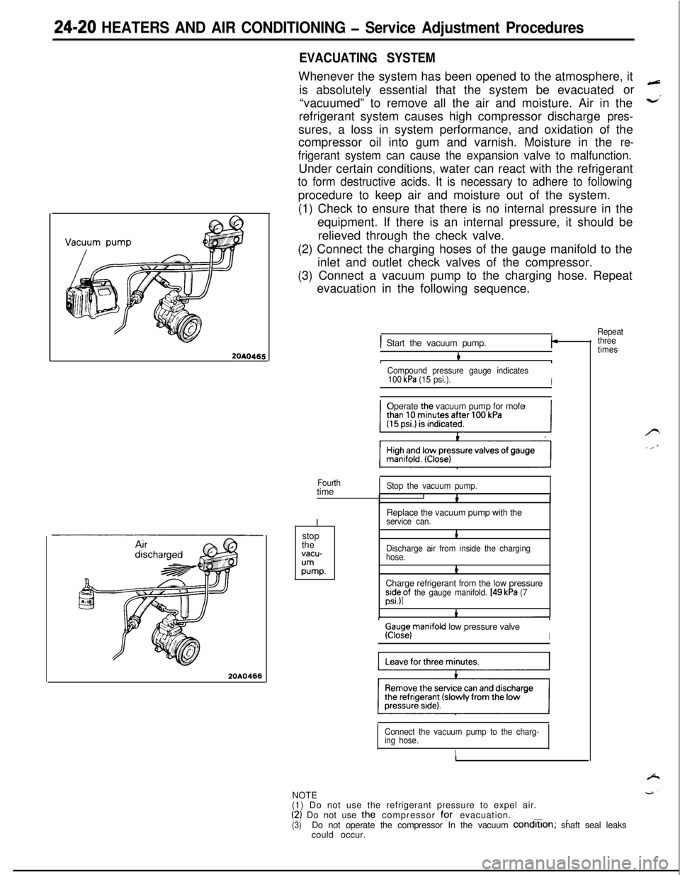
EVACUATING SYSTEMWhenever the system has been opened to the atmosphere, it
is absolutely essential that the system be evacuatedor
“vacuumed” to remove all the air and moisture. Air in the
refrigerant system causes high compressor discharge
pres-sures, a loss in system performance, and oxidation of the
compressor oil into gum and varnish. Moisture in the
re-
frigerant system can cause the expansion valve to malfunction.Under certain conditions, water can react with the refrigerant
to form destructive acids. It is necessary to adhere to followingprocedure to keep air and moisture out of the system.
(1) Check to ensure that there is no internal pressure in the
equipment. If there is an internal pressure, it should be
relieved through the check valve.
(2) Connect the charging hoses of the gauge manifold to the
inlet and outlet check valves of the compressor.
(3) Connect a vacuum pump to the charging hose. Repeat
evacuation in the following sequence.
Repeat
) Start the vacuum pump.I-
bIICompound pressure gauge indicates
100 kPa (15 psi.).IOperate the vacuum pump for mofe
Fourthtime
IStop the vacuum pump.IbReplace the vacuum pump with the
service can.stop
the
vacu-
;Ummp.
1
Discharge air from inside the charging
hose.
bCharge refrigerant from the low pressure
;s”;pf the gauge manifold. [49 kPa (7
Ga;iejmanifold low pressure valveI
Connect the vacuum pump to the charg-
ing hose.
INOTE
(1) Do not use the refrigerant pressure to expel air.
(‘2) Do not use the. compressor for evacuation.___(3)Do not operate the compressor In the vacuum condrtlon; shaft seal leaks
could occur.
three
times
Page 1215 of 1216

EMISSION CONTROL SYSTEMS- Exhaust Gas Recirculation (EGR) Svstem25-19
\\
7EM0043
. .
6EM0187
EGR TEMPERATURE SENSOR NHCZB
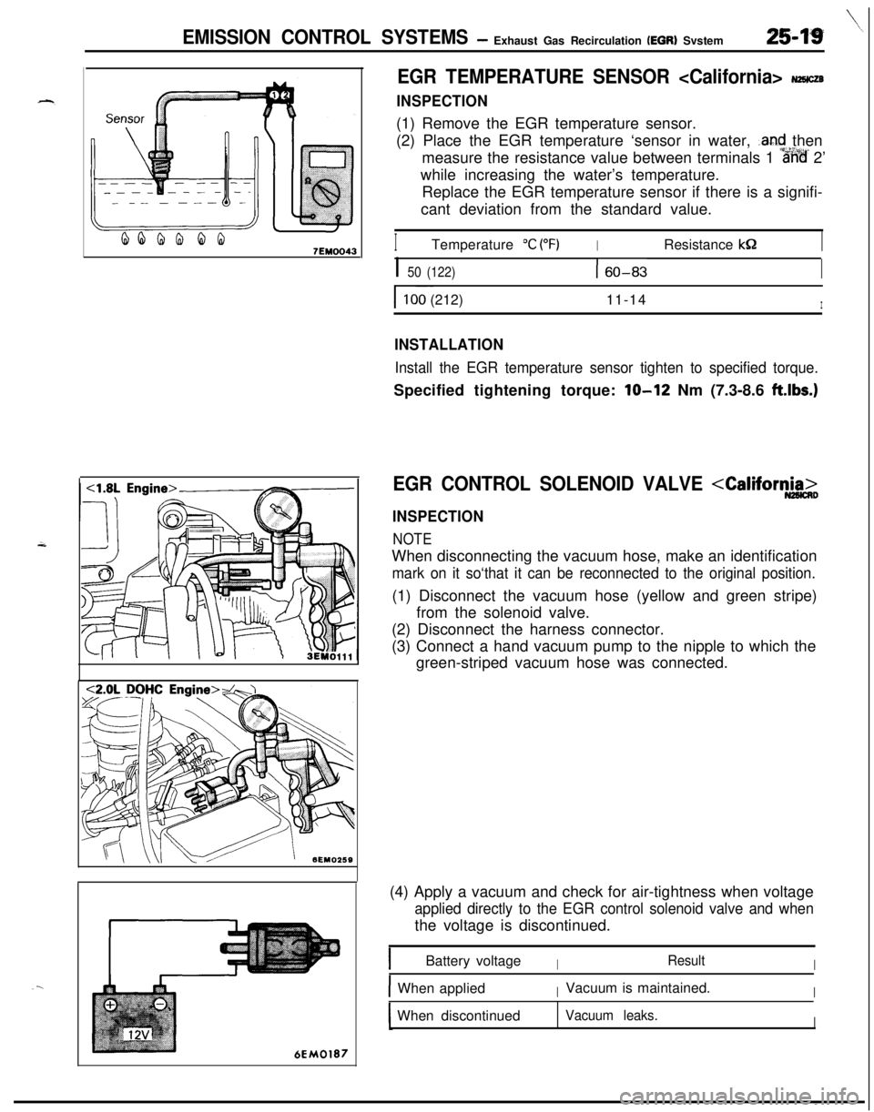
INSPECTION(1) Remove the EGR temperature sensor.
(2) Place the EGR temperature ‘sensor in water,
.and then
measure the resistance value between terminals 1
%%’ 2’
while increasing the water’s temperature.
Replace the EGR temperature sensor if there is a signifi-
cant deviation from the standard value.
ITemperature “C (“F)IResistance kS2I
I 50 (122)160-83I
I ~~100 (212)11-14I
INSTALLATION
Install the EGR temperature sensor tighten to specified torque.Specified tightening torque:
lo-12 Nm (7.3-8.6 ft.lbs.)
EGR CONTROL SOLENOID VALVE
INSPECTION
NOTEWhen disconnecting the vacuum hose, make an identification
mark on it so‘that it can be reconnected to the original position.(1) Disconnect the vacuum hose (yellow and green stripe)
from the solenoid valve.
(2) Disconnect the harness connector.
(3) Connect a hand vacuum pump to the nipple to which the
green-striped vacuum hose was connected.
(4) Apply a vacuum and check for air-tightness when voltage
applied directly to the EGR control solenoid valve and whenthe voltage is discontinued.
IBattery voltageIResultI
IWhen appliedIVacuum is maintained.IWhen discontinued
Vacuum leaks.I