1991 MITSUBISHI ECLIPSE lights
[x] Cancel search: lightsPage 513 of 1216

FUEL SYSTEM - MPI System inspection <1.8L Engine>14-59
--..When it is noticed that an irregularity has continued for a
specified time or longer from when the irregular signal is
initially monitored. Passing a certain number, the engine
control unit judges that an irregularity has occurred, memorizesthe malfunction code, and outputs the signal to the
self-diagnosis output terminal.
There are 14 diagnosis items, and the diagnosis results can beread out with a voltmeter.
Moreover, since memorization of the malfunction codes is
backed up directly by the battery, the diagnosis results are
memorized even if the ignition key is turned off. The malfunc-
tion codes will, however, be erased when the battery terminal
or the engine control unit connector is disconnected.
Caution
If the sensor connector is disconnected with the ignition
switch turned on, the malfunction code is memorized. In
this case, disconnect the battery terminal’
(-) for 10seconds or more, and the diagnosis memory will be
erased.The 14 diagnosis items are provided as follows, and if plural
items are activated, they are all indicated sequentially from thesmallest code number.
perature sensor
CautionFor the malfunction code of the ignition timing adjustment
signal, the light for the ignition timing adjustment terminal
lights up when short-circuited to ground.
Consequently, it is output when the ignition timing
adjustment is grounded when adjusting ignition timing,
but in this case there is not abnormality.
CHECK PROCEDURE (SELF-DIAGNOSIS)N14PCAElPrecautions for Operation
(1) When battery voltage is low, no detection of failure is
possible. Be sure to check the battery for voltage and otherconditions before starting the test.
(2) Diagnosis item is erased if the battery or the engine controlunit connector is disconnected. Do not disconnect the
battery before the diagnosis result is completely read.
(3) After check and correction are over, disconnect ground
cable for
10 seconds or more from negative terminal of
battery and connect it again to make sure that failure code
is erased.
Page 560 of 1216

14-106ENGINE CONTROL - Service Adjustment Procedures
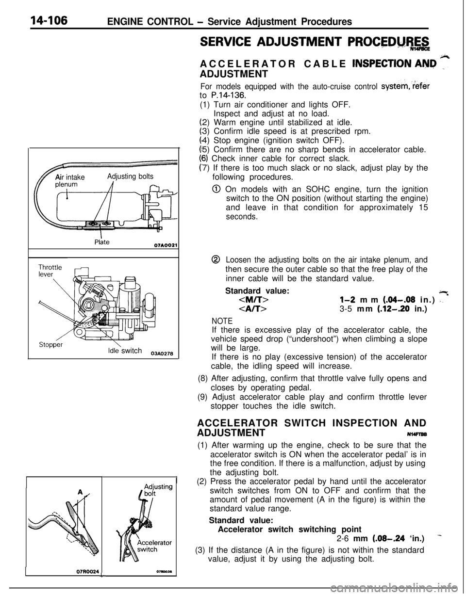
TAir intakeAdjusting bolts
Idle switch03A,,2.8
07RQ024L
I
SERVICE ADJUSTMENT PROCEDM%,&ACCELERATOR CABLE
CNSPECTION AN&I ”ADJUSTMENT
For models equipped with the auto-cruise control systemreferto
P.14-136.(1) Turn air conditioner and lights OFF.
Inspect and adjust at no load.
2) Warm engine until stabilized at idle.
3) Confirm idle speed is at prescribed rpm.
4) Stop engine (ignition switch OFF).
5) Confirm there are no sharp bends in accelerator cable.
6) Check inner cable for correct slack.
7) If there is too much slack or no slack, adjust play by the
following procedures.
@ On models with an SOHC engine, turn the ignition
switch to the ON position (without starting the engine)
and leave in that condition for approximately 15
seconds.@
Loosen the adjusting bolts on the air intake plenum, andthen secure the outer cable so that the free play of the
inner cable will be the standard value.
Standard value:
jlr
3-5 mm (.12-.20 in.)
NOTEIf there is excessive play of the accelerator cable, the
vehicle speed drop (“undershoot”) when climbing a slope
will be large.
If there is no play (excessive tension) of the accelerator
cable, the idling speed will increase.
(8) After adjusting, confirm that throttle valve fully opens and
closes by operating pedal.
(9) Adjust accelerator cable play and confirm throttle lever
stopper touches the idle switch.
ACCELERATOR SWITCH INSPECTION AND
ADJUSTMENT
NlWlEB(1) After warming up the engine, check to be sure that the
accelerator switch is ON when the accelerator pedal’ is in
the free condition. If there is a malfunction, adjust by using
the adjusting bolt.
(2) Press the accelerator pedal by hand until the accelerator
switch switches from ON to OFF and confirm that the
amount of pedal movement (A in the figure) is within the
standard value range.
Standard value:
Accelerator switch switching point
2-6 mm
(.08-.24 ‘in.)
(3) If the distance (A in the figure) is not within the standard
value, adjust it by using the adjusting bolt.
Page 695 of 1216

TRANSAXLE ’
MANUAL AND AUTOMATICCONTENTS
;-AUTOMATICTRANSAXLE
.....................................................137ANNULUS GEAR AND TRANSFER DRIVE GEAR SET (F4A22)..........315ANNULUS GEAR AND TRANSFER DRIVE GEAR SET(F4A33.W4A33)...........................................................................................317CENTERDIFFERENTIAL(W4A33).............................................................329DIFFERENTIAL............................................................................................319ENDCLUTCHASSEMBLY.........................................................................309EXTENSIONHOUSINGASSEMBLY(W4A33).........................................337FRONTCLUTCHASSEMBLY....................................................................302FRONTOUTPUTSHAFT(W4A33)...........................................................332GENERALINFORMATION.........................................................................137KICKDOWNSERVO....................................................................................322LOW-REVERSEBRAKE..............................................................................323OILPUMP...................................................................................................299PLANETARYGEARSET............................................................................311PLANETARYGEARSET............................................................................313REARCLUTCHASSEMBLY(F4A22)........................................................304REARCLUTCHASSEMBLY(FQA33sW4A33)............................................307SERVICEADJUSTMENTPROCEDURES..................................................Drive
Shaft,OilSealsReplacement....................................................;;;
InhibitorSwtchAdjustment................................................................21 1KeyInterlockMechanismCheck.....................................................KrckdownServoAdjustment..................................zii..............................
LinePressureAdjustment...................................................................213
ReducingPressureAdjustment.........................................................214Selector Lever Operation Check........................................................210ShiftLockMechanismCheck...............................................................21 1SpeedometerCableReplacement.........................................................Throttle-posltipn Sensor Adjustment.................................................z2:
TransaxleFluIdLevelInspectIon......................................................209
TransaxleFluidReplacement.............................................................209
SPECIALTOOLS.........................................................................................SPECIFICATIONS........................................................................................;“5”9
GeneralSpeclficatlons..................................................................1%Lubricants..................................................................................Sealants and Adhesives..............................................................izi
Serwce Speclflcatlons..................................................159...............Spacer andSnapRing.,.,.............................................................Spacer Set..................................................................1::Torque Speclflcatlons...........................................166Valve Body Spring Identification Chart.....................
.................160
SPEEDOMETERGEARASSEMBLY..........................................................TRANSAXLEASSEMBLY(WA22)............................................................zTRANSAXLE
ASSEMBLY(F4A33.W4A33)................................................TRANSAXLECONTROL.............................................................................;;;TRANSAXLE
OILCOOLER........................................................................TRANSFER..................................................................................................fg
TRANSFERASSEMBLY.............................................................................333TRANSFERCASEADAPTERSUBASSEMBLY(W4A33).......................339TRANSFER CASE SUB ASSEMBLY (W4A33)341TRANSFER SHAFT (F4A33)TROUBLESHOOTING..................................................................................................................................................................................................f;;VALVE
BODY.............................................................................................324
MANUAL TRANSAXLE
5TH-SPEEDSYNCHRONIZERASSEMBLY...............................................42GENERALINFORMATION.........................................................................2.-.INPUTfj,-,A,TASSEMBLY
INTERMEDIATE GEAR ASSEMBLY..........................................................56OUTPUT
SHAFT ASSEMBLY....................................................................61SERVICEADJUSTMENTPROCEDURES..................................................DriveShaftOilSealsReplacement......................................................;;Speedometer Cable Replacement.........................................................
Transaxle Oil Level
InspectIon..............................................................‘liTransaxle Oil Replacement....................................................................
I3
SHIFTLEVERASSEMBLY.........................................................................SHIFTRAILSANDFORKS........................................................................g
SPECIALTOOLS.........................................................................................SPECIFICATIONS........................................................................................1:
General Specifications5Lubricants..........................................................................................................................................................................10Sealants and Adhesives
Service Specifications
....................................................................................................................................................1:Snap Ring (for Adjustment) and Spacer...............................................
Torque Specifications.............................................................................
i
SPEEDOMETERGEARASSEMBLY..........................................................TRANS&G.E................................................................................................zTRANSAXLEA!jSEMBLY
TROUBLESHOOTING..................................................................................12
MANUAL TRANSAXLE
CENTERDIFFERENTIAL.............................................................................103CLUTCHHOUSINGASSEMBLY...............................................................DRIVE BEVEL GEAR ASSEMBLY;g
...... .......................................................DRIVENBEVELGEARASSEMBLY...................................a......................EXTENSIONHOUSINGASSEMBLY.........................................................;g
5Tf.jSPEEDSYNCHRONIZERASSEMBLY...............................................101
FRONTDlFFERENTlAL...............................................................................106
FRONTOUTPUTSHAFTASSEMBLY......................................................106
GENERALI~~~~MATN)N...............................................................,.,.......66INPUTSHAFTASSEMBLY........................................................................l~ER,“,EDlATEGEARASSMBLY..........................................................;;i
SERVICEADJUSTMENTPROCEDURES..................................................Drive Shaft Oil Seals Replacement......................................................;;Speedometer Cable Replacement.........................................................
Transaxle
Ojl Level lnspectlon..............................................................;l
Transaxle 011 R~pb33ment....................................................................79Transfer
OilSealReplacement.............................................................80
SHIFTLEVERASSEMBLY.........................................................................SHIFTRAILASSEMBLY............................................................................,z
SPECIALTOOLS.........................................................................................76
SPECIFICATIONS........................................................................................6g
GeneralSpecifications...........................................................................6g
Lubricants...............................................................................................75
SealantsandAdhesives........................................................................76
ServiceSpecifications............................................................................6gSnap Ring (for Adjustment) and Spacer...............................................7 o
TorqueSpecifications.............................................................................74
SPEEDOMETERGEARASSEMBLY..........................................................TRANSAXLE................................................................................................1:TRANSAXLEASSEMBLY...........................................................................86TRANSAXLE
CONTROL
.............................................................................TRANSFER...............................................................................................
g.._TRANSFERA!333lBLY.............................................................................,24
TRANSFERCASEADAPTERSUBASSEMBLY.......................................131TRANSFERCASESUBASSEMBLY.........................................................TR,,UBLES,,OO,,NG..................................................................................1;;
Page 1095 of 1216

BODY - Fender
FENDER
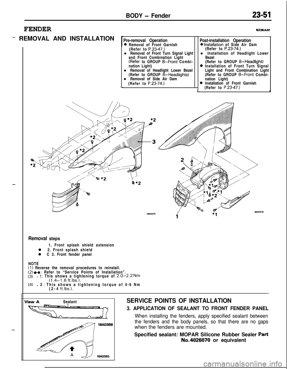
:- REMOVAL AND INSTALLATION
-.
Pre-removal Operation0 Removal of Front Garnish
(Refer to P.23-47.)l Removal of Front Turn Signal Light
and Front Combination Light
(Refer to GROUP 8-Front Combi-
nation Light)
l Removal of Headlight Lower Bezel
(Refer to GROUP
8-Headlights)l Removal of Side Air Dam
(Refer to
P.23-74.)LLu23KAAr
Post-installation Operation0 Installation of Side Air Dam
(Refer to P.23-74.)l Installation of Headlight Lower
Bezel
(Refer to GROUP
8-Headlight)0 Installation of Front Turn Signal
Light and Front Combination Light
(Refer to GROUP
8-Front Combi-
nation Light)
0 Installation of Front Garnish
(Refer to P.23-47.)J
Removal steps1. Front splash shield extension
l 2. Front splash shield
l C 3. Front fender panel
NOTE
(1) Reverse the removal procedures to reinstall.(2) .a : Refer to “Service Points of Installation”.
(3)l 1 : This shows a tightening torque of 2.0-2.2 Nm(1 .4-l .6 ft.lbs.1.(4)l 2 : This shows a tightening torque of 4-6 Nm
(2-4 ft.lbs.1.
View ASealantSERVICE POINTS OF INSTALLATION
3. APPLICATION OF SEALANT TO FRONT FENDER PANEL
When installing the fenders, apply specified sealant between
the fenders and the body panels, so that there are no gapswhen the fenders are mounted.
Specified sealant: MOPAR Silicone Rubber Sealer
PartNo.4026070 or equivalent
Page 1133 of 1216

BODY - Trims/Headlining23-89
HEADLINING
PEMOVAL AND INSTALLATION
Pm-removal Operationl Removal of Center Pillar Trim
(Refer to
P.23-85.)l Removal of Front Pillar Trim
(Refer to
P.23-85.)l Removal of Guide Rail
(Refer to
P.23-94.)
Post-installation Operation0 Installation of Guide Rail
(Refer to P.23-94.)l Installation of Front Pillar Trim
(Refer to
P.23-85.)l Installation of Center Pillar Trim
(Refer to
P.23-85.)
Vehicles without sunroof
Vehicles with sunroof
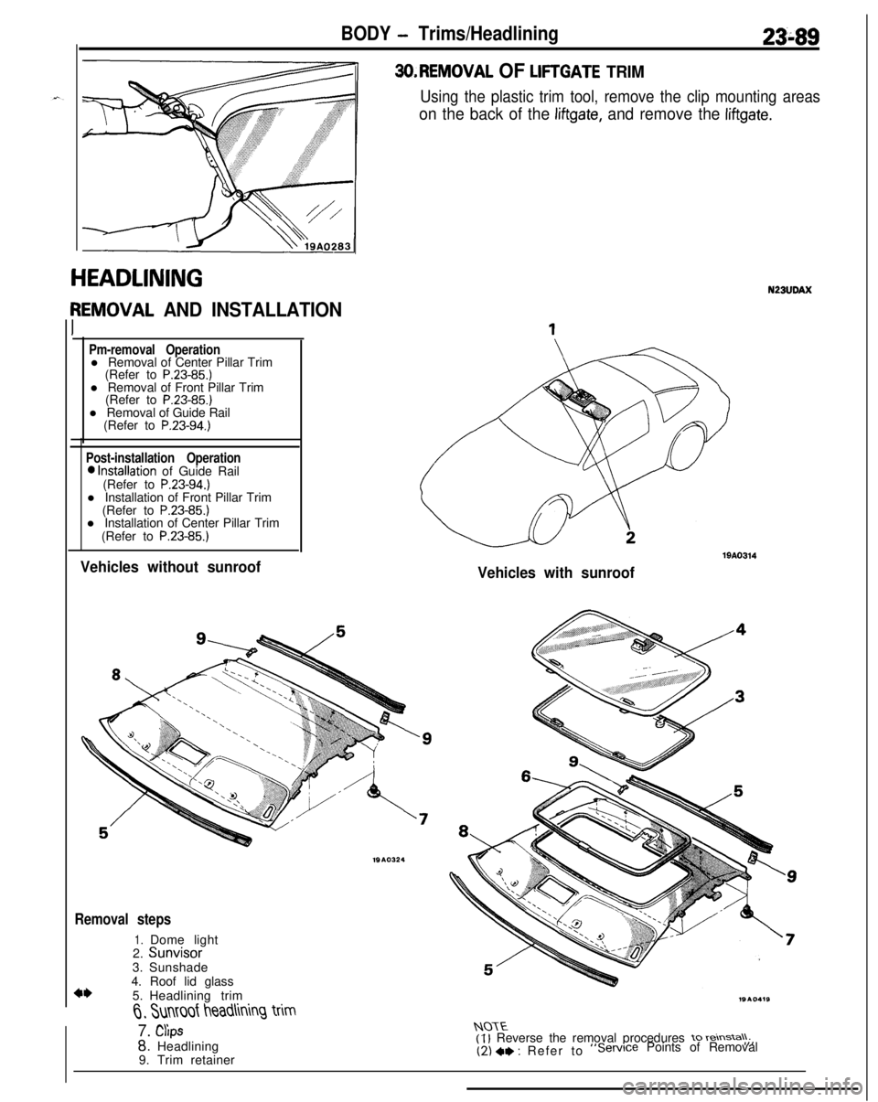
3O.REMOVAL OF LIFTGATE TRIM
Using the plastic trim tool, remove the clip mounting areas
on the back of the liftgate, and remove the liftgate.
Removal steps
1.2.Dome lightSunvisor3.Sunshade
4*4. Roof lid glass
5.Headlining trim
6, Sunmf headlining trim
7. CYlps
8. Headlining
9. Trim retainer
19A0314
N23UDAX
NOTE(I l Reverse the removal procedures to reinsta\\;,(2) +e : Refer to“Service Points of Removal
Page 1169 of 1216

HEATERS AND AIR CONDITIONING - Service Adjustment Procedures 24-25
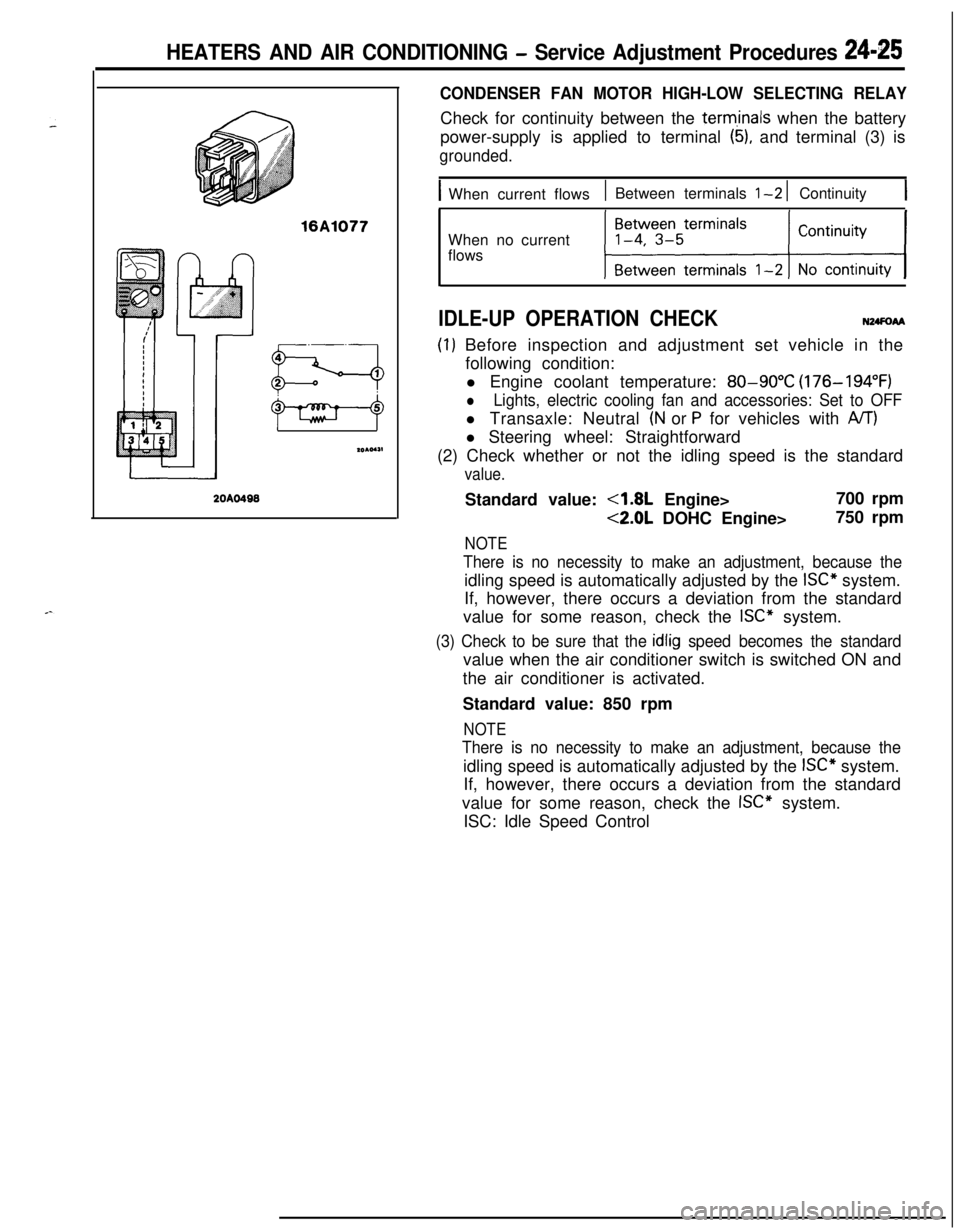
16A1077
20AO499
CONDENSER FAN MOTOR HIGH-LOW SELECTING RELAYCheck for continuity between the
term,inals when the battery
power-supply is applied to terminal
(5), and terminal (3) is
grounded.
IWhen current flows1 Between terminals l-2 1 Continuity1When no current
flows
IDLE-UP OPERATION CHECKN24FoAA
(I) Before inspection and adjustment set vehicle in the
following condition:
l Engine coolant temperature:
80-90°C (176-194°F)
lLights, electric cooling fan and accessories: Set to OFFl Transaxle: Neutral
(N or P for vehicles with A/T)l Steering wheel: Straightforward
(2) Check whether or not the idling speed is the standard
value.Standard value:
4.8L Engine>700 rpm
<2.0L DOHC Engine>750 rpm
NOTE
There is no necessity to make an adjustment, because theidling speed is automatically adjusted by the
ISC” system.
If, however, there occurs a deviation from the standard
value for some reason, check the
ISC” system.
(3) Check to be sure that the idlig speed becomes the standardvalue when the air conditioner switch is switched ON and
the air conditioner is activated.
Standard value: 850 rpm
NOTE
There is no necessity to make an adjustment, because theidling speed is automatically adjusted by the
ISC” system.
If, however, there occurs a deviation from the standard
value for some reason, check the
ISC” system.
ISC: Idle Speed Control