1991 MITSUBISHI ECLIPSE ESP
[x] Cancel search: ESPPage 233 of 1216

CLUTCH - Specifications/Special Tool6-3
TORQUE SPECIFICATIONSNMCC-Items
Nmftlbs.Clutch pedal to clutch pedal support bracket
20-2514-18
Clutch pedal support bracket
8-12
6-9
Clutch pedal support bracket to firewall
10-157-l 1Stop light switch
10-157-11
Brake booster installation nut
11-17
8-12
Master cylinder to firewall
10-157-11
Pedal rod to clutch pedal support bracket
17-2612-19
Clutch pedal bracket
8-l 26-9
Pedal rod to clutch pedal bracket
17-2612-19
Clutch tube flare nut
13-17
9-12
Air cleaner bracket
8-12
6-9
Clutch tube clamp to body
8-l 26-9
Reservoir band
5-7
4-5
Clutch release cylinder
15-22
11-16Clutch release cylinder to union bolt
2518Bleeder plug
9-13
7-9
Fulcrum35-4225-30Clutch cover assembly
15-22
11-16
- LUBRICANTSNOSCD-Items
Contact surface of release bearing and fulcrum of clutch
release fork
Inner surface of clutch release bearing
Inner surface of clutch disc splineSpecified lubricants
MOPAR Multi-mileage Lubricant
Part
No.2525035 or equivalent
Contact portion of release fork to release cylinder push rod
Bushing,
clevis pin, washer and bushing
Inner surface of clutch release cylinder and outer
circumference of piston and cupMOPAR Brake Fluid/Conforming to
DOT3Inner surface of clutch master cylinder and outer
circumference of piston assembly
SPECIAL TOOL
ToolNumber
MD9981 26
NameUse
Clutch disc center
guideClutch disc center hole alignment
\\
Page 250 of 1216
7-2COOLING - Specifications
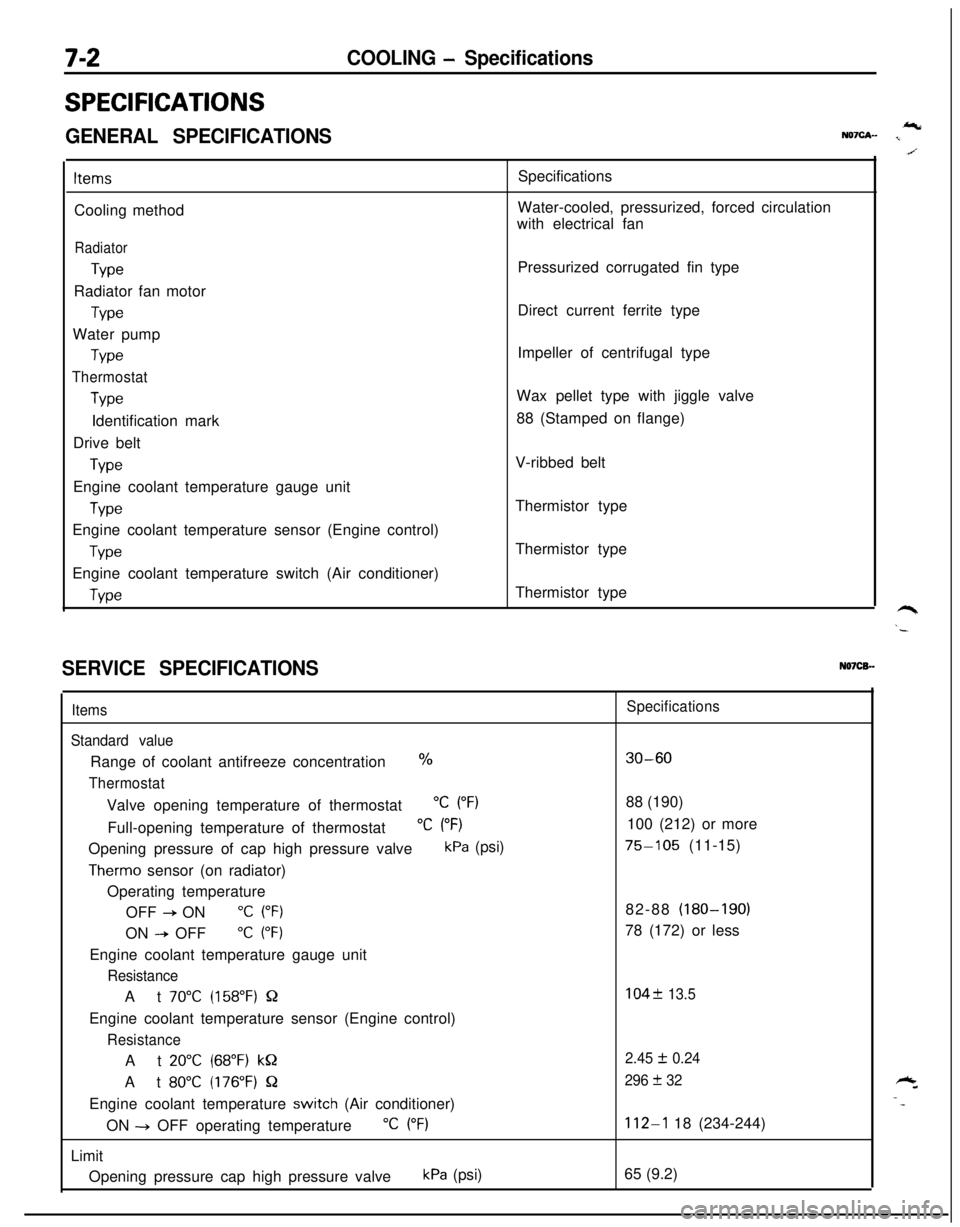
SPECIFICATIONS
GENERAL SPECIFICATIONSIcNQ7cA- I
ItemsCooling method
Radiator
TypeRadiator fan motor
TypeWater pump
Type
Thermostat
TypeIdentification mark
Drive belt
TypeEngine coolant temperature gauge unit
WeEngine coolant temperature sensor (Engine control)
TypeEngine coolant temperature switch (Air conditioner)
WeSpecifications
Water-cooled, pressurized, forced circulation
with electrical fan
Pressurized corrugated fin type
Direct current ferrite type
Impeller of centrifugal type
Wax pellet type with jiggle valve
88 (Stamped on flange)
V-ribbed belt
Thermistor type
Thermistor type
Thermistor type
SERVICE SPECIFICATIONSN07CB.-
Items
Standard valueRange of coolant antifreeze concentration
%
ThermostatValve opening temperature of thermostat
“C (“F)Full-opening temperature of thermostat
“C (“F)Opening pressure of cap high pressure valve
kPa (psi)
Therm0 sensor (on radiator)
Operating temperature
OFF
+ ON“C (“F)ON
--P OFF“C (“F)Engine coolant temperature gauge unit
ResistanceAt
70°C (158°F) QEngine coolant temperature sensor (Engine control)
ResistanceAt
20°C (68°F) kQAt
80°C (176°F) QEngine coolant temperature
switch (Air conditioner)
ON -+ OFF operating temperature
“C (“F)Limit
Opening pressure cap high pressure valve
kPa (psi)
Specifications
30-6088 (190)
100 (212) or more
75-105 (11-15)
82-88 (180-190)
78 (172) or less
104f 13.5
2.45
I!I 0.24
296
+ 32
112-l 18 (234-244)
65 (9.2)
Page 339 of 1216
ENGINE - Cylinder Head and Valve9-55
3EN026
w -w===j=Margin , EN034
Squareness
IFree length
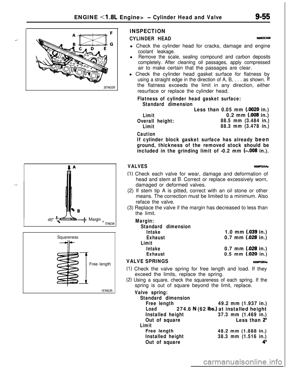
INSPECTION
CYLINDER HEADNosocAMl Check the cylinder head for cracks, damage and engine
coolant leakage.l
Remove the scale, sealing compound and carbon deposits
completely. After cleaning oil passages, apply compressedair to make certain that the passages are clear.
l Check the cylinder head gasket surface for flatness by
using a straight edge in the direction of A, B, . . . as shown. Ifthe flatness exceeds the limit in any direction, either
resurface or replace the cylinder head.
Flatness of cylinder head gasket surface:
Standard dimension
Limit
Overall height:
Limit
Caution
Less than 0.05 mm (0020 in.)
0.2 mm (008 in.)
88.5 mm (3.484 in.)
88.3 mm (3.478 in.)
If cylinder block gasket surface has already been
ground, thickness of the removed stock should be
included in the grinding limit of -0.2 mm
(-,008 in.).
VALVESNo9PGMa
(1) Check each valve for wear, damage and deformation of
head and stem at
B. Correct or replace excessively worn,
damaged or deformed valves.
(2) If stem tip A is pitted, correct with an oil stone or other
means. The correction must be limited to a minimum. Also
reface the valve.
(3) Replace the valve if the margin has decreased to less than
the limit.
Margin:
Standard dimension
Intake1.0 mm (.039 in.)
Exhaust0.7 mm (028 in.)
Limit
Intake0.7 mm (.028 in.)
Exhaust0.5 mm LO20 in.)
VALVE SPRINGSNOWGh
(1) Check the valve spring for free length and load. If they
exceed the limits, replace the spring.
(2) Using a square, check the squareness of each spring. If thespring is out of square beyond the limit, replace.
Valve spring:
Standard dimension
Free length
49.2 mm (1.937 in.)
Load274.6 N (62 Ibs.) at installed height
Installed height37.3 mm (1.469 in.)
Out of square
Less than 2”
Limit
Free length48.2 mm (1.888 in.)
Installed height38.3 mm (1.516 in.)
Out of square4”
Page 341 of 1216

ENGINE <1.8L Engine> - Cylinder Head and Valve9-57
Enamel-
coating
sideSpring
retainerStem seal
Spring- seat
3EN324intake side
3EN315Front of engine
I,Exhaust side
11./7. INSTALLATION OF VALVE SPRINGInstall the valve spring with its enamel coated end toward
the valve spring retainer.
9.15. INSTALLATION OF RETAINER LOCK(1) Using the special tool, compress the spring, and then
install the retainer lock.
Caution
When compressing the spring, check to see that the
valve stem seal is not pressed to the bottom of the
retainer.
(2) Make certain that retainer locks are positively installed.
1. INSTALLATION OF CYLINDER HEAD BOLTSUsing the special tool, tighten in the order shown in two or
three steps, gradually tighten. Finally tighten to the speci-
fied torque.
Page 399 of 1216
ENGINE <2.0L DOHC Engine> - Cylinder Head and Valve9-115
1Ghde I.D.
Guide O.D.
1 EN298
Valve
ispring
*seat
\ Iril
: :
MD998737
Valvestem
seal
SpringVALVE GUIDE
NOSPGCCMeasure the clearance between the valve guide and valve
stem and, if the clearance exceeds the limit, replace the valve
guide or valve, or both.
Standard value:
Intake
0.02-0.047 mm (.OOOS-.0019 in.)
Exhaust0.05-0.085 mm (.002-.0033 in.)
Limit:
Intake0.10 mm
(.0040 in.)
Exhaust0.15 mm (.0059 in.)
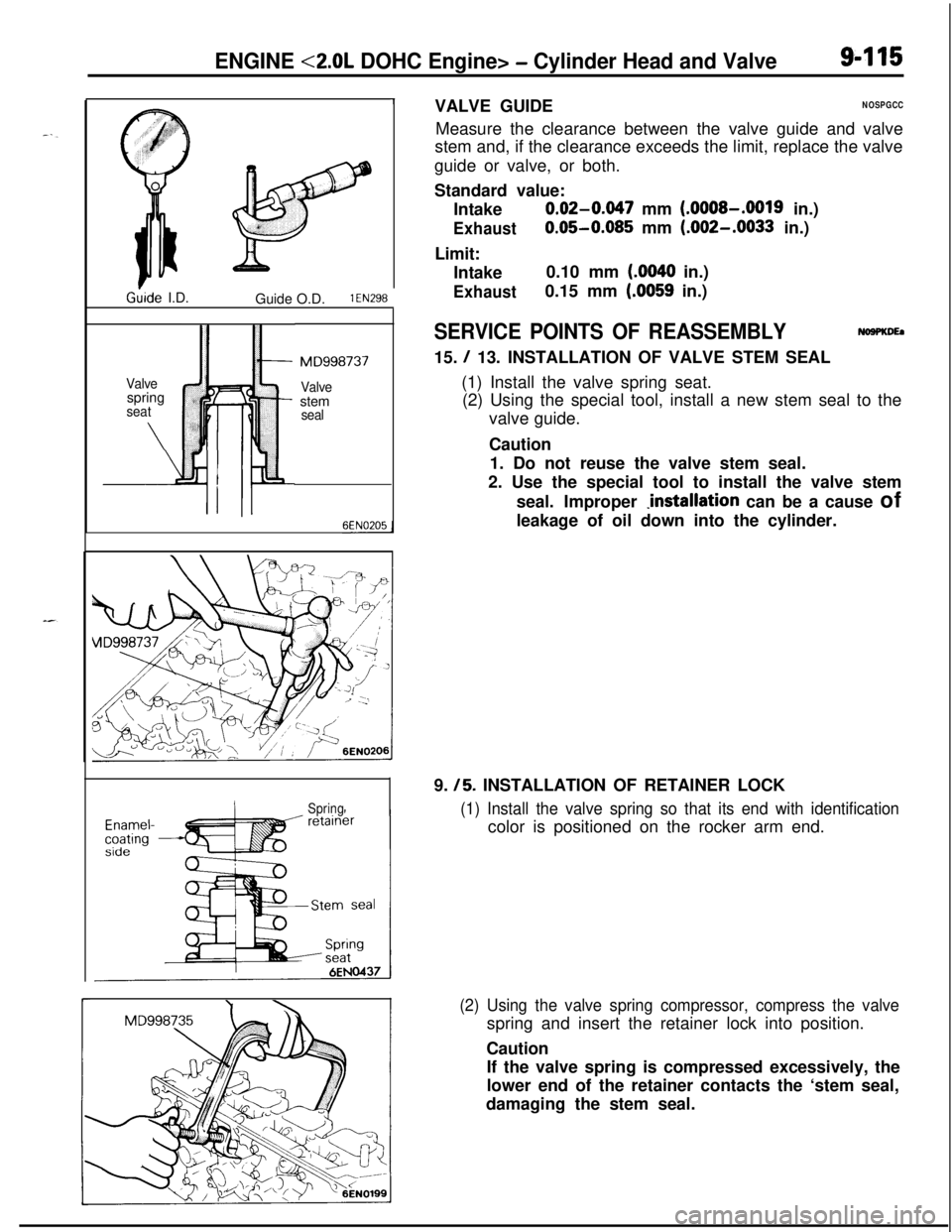
SERVICE POINTS OF REASSEMBLYNoaPKDEa15.
/ 13. INSTALLATION OF VALVE STEM SEAL
(1) Install the valve spring seat.
(2) Using the special tool, install a new stem seal to the
valve guide.
Caution
1. Do not reuse the valve stem seal.
2. Use the special tool to install the valve stem
seal. Improper
Jnstallation can be a cause of
leakage of oil down into the cylinder.
9.
/5. INSTALLATION OF RETAINER LOCK
(1) Install the valve spring so that its end with identificationcolor is positioned on the rocker arm end.
(2) Using the valve spring compressor, compress the valvespring and insert the retainer lock into position.
Caution
If the valve spring is compressed excessively, the
lower end of the retainer contacts the ‘stem seal,
damaging the stem seal.
Page 412 of 1216
9-128ENGINE <2.0L DOHC Enaine> - Piston and Connectina Rod
DEN050
6EN185
95EN057
Piston ringring gap6EN037
JSERVICE POINTS OF DISASSEMBLY
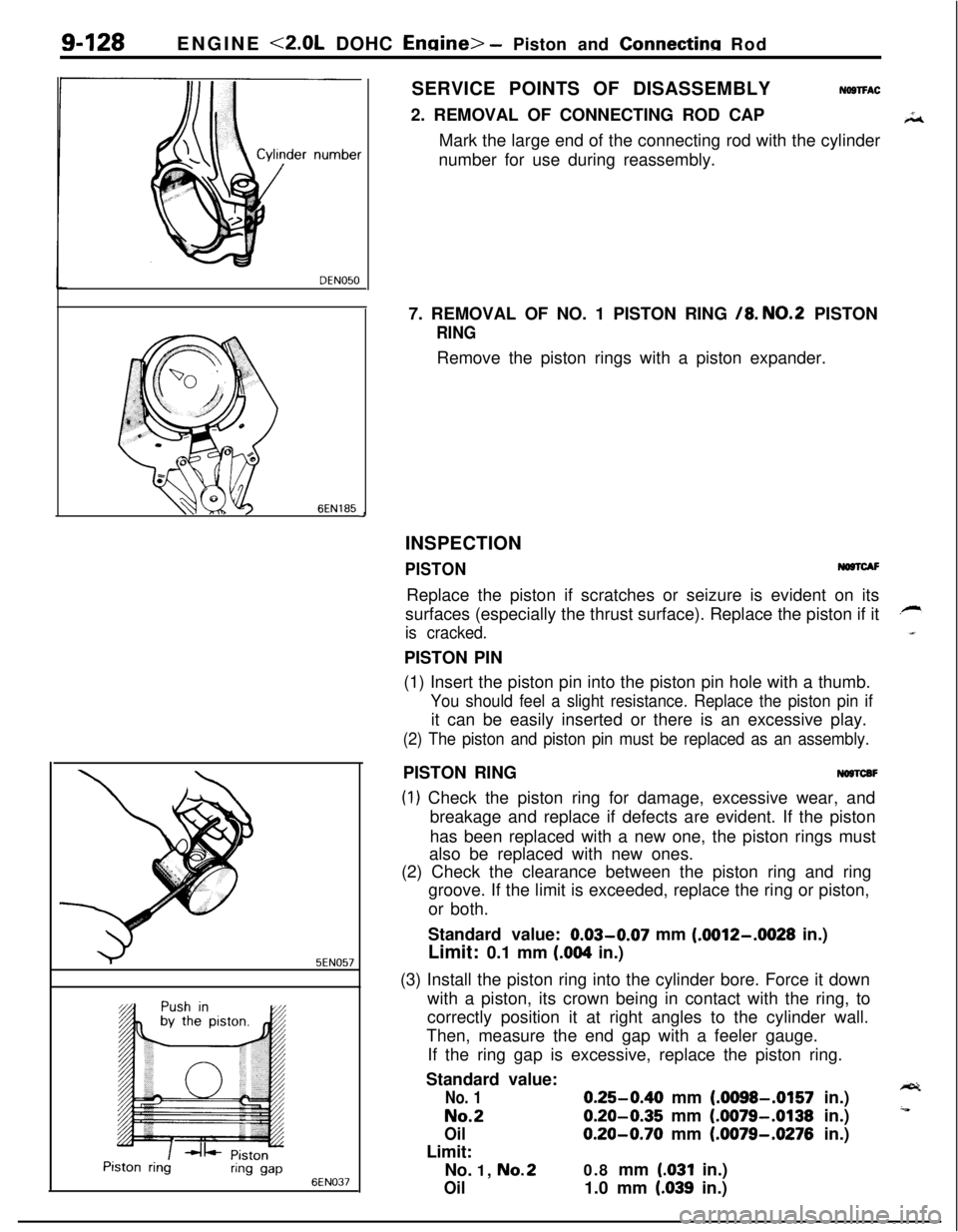
NOSTFAC2. REMOVAL OF CONNECTING ROD CAP
Mark the large end of the connecting rod with the cylinder
number for use during reassembly.
7. REMOVAL OF NO. 1 PISTON RING
/8. NO.2 PISTON
RINGRemove the piston rings with a piston expander.
INSPECTION
PISTONNO@lCAFReplace the piston if scratches or seizure is evident on its
surfaces (especially the thrust surface). Replace the piston if it
is cracked.PISTON PIN
(1) Insert the piston pin into the piston pin hole with a thumb.
You should feel a slight resistance. Replace the piston pin ifit can be easily inserted or there is an excessive play.
(2) The piston and piston pin must be replaced as an assembly.PISTON RING
NOSTCBF
(1) Check the piston ring for damage, excessive wear, and
breakage and replace if defects are evident. If the piston
has been replaced with a new one, the piston rings must
also be replaced with new ones.
(2) Check the clearance between the piston ring and ring
groove. If the limit is exceeded, replace the ring or piston,
or both.
Standard value: 0.03-0.07 mm
(.0012-.0028 in.)
Limit: 0.1 mm
(.004 in.)
(3) Install the piston ring into the cylinder bore. Force it down
with a piston, its crown being in contact with the ring, to
correctly position it at right angles to the cylinder wall.
Then, measure the end gap with a feeler gauge.
If the ring gap is excessive, replace the piston ring.
Standard value:
No. 10.25-0.40 mm (.0098-.0157 in.)
No.20.20-0.35 mm (.0079-.0138 in.)
Oil0.20-0.70 mm (.0079-.0276 in.)
Limit:
No. 1,
No.20.8 mm (.031 in.)
Oil1.0 mm (.039 in.)
Page 424 of 1216
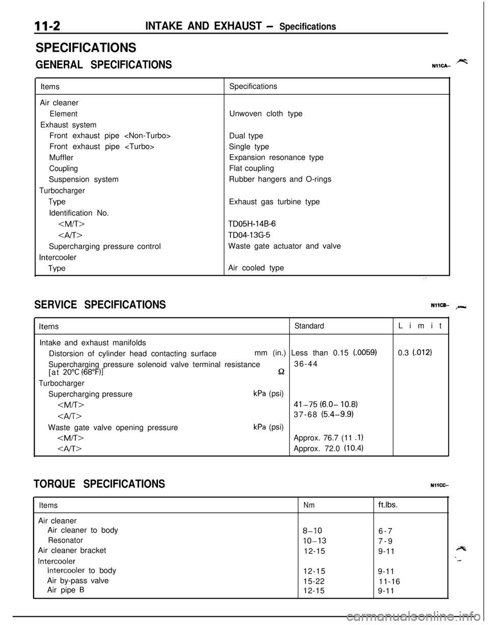
11-2INTAKE AND EXHAUST - Specifications
SPECIFICATIONS
GENERAL SPECIFICATIONS.prtNIICA-Items
Air cleaner
ElementExhaust system
Front exhaust pipe
Front exhaust pipe
Muffler
CouplingSuspension system
Turbocharger
TypeIdentification No.
4iT>Supercharging pressure control
Intercooler
TypeSpecifications
Unwoven cloth type
Dual type
Single type
Expansion resonance type
Flat coupling
Rubber hangers and O-rings
Exhaust gas turbine type
TD05H-14B-6
TD04-13G-5Waste gate actuator and valve
Air cooled type
SERVICE SPECIFICATIONSNllCB- spr*
ItemsStandardIntake and exhaust manifolds
Distorsion of cylinder head contacting surfacemm (in.) Less than 0.15
(.0059)Supercharging pressure solenoid valve terminal resistance36-44
[at
20°C (68”F)lQ
TurbochargerSupercharging pressure
kPa (psi)
kPa (psi)
0.3
l.0121
TORQUE SPECIFICATIONSNllCC-
ItemsAir cleaner
Air cleaner to body
ResonatorAir cleaner bracket
Intercooler
Intercooler to body
Air by-pass valve
Air pipe
B
Nmftlbs.
8-106-7
10-137-9
12-15
9-11
12-15
9-11
15-22
11-16
12-15
9-11
Page 455 of 1216

14-IFUEL SYSTEM
CONTENTS
AUTO-CRUISECONTROLSYSTEM...........................................109AUTO-CRUISECONTROL.......................................................140SERVICEADJUSTMENTPROCEDURES..............................135Accelerator Cable, Throttle Cable and Auto-cruise
ControlCableInspectionandAdjustment........................136Auto-cruise
ControlSystemInspection.............................135lndrvrdualPartsInspection..................................................137SPECIFICATIONS.....................................................................109GeneralSpecifications.......................................................109ServiceSpecifications
.........................................................109Torque Specrfications..........................................................109TROUBLESHOOTING...............................................................110Auto-CruiseControlCircurt................................................128Auto-cruise
ControlComponentsLocation........................126Auto-cruise Control Related Harnesses
.............................125Check Chart
........................................................................114Input Check.........................................................................123Self-diagnosis
Check..........................................................121Troubleshootrng
Quick-referenceChart..............................110ENGINECONTROL.......................................................................105ENGINECONTROL..................................................................107--SERVICEADJUSTMENTPROCEDURES..............................106Accelerator Cable Inspection and Adjustment..................106Accelerator Switch Inspectron and Adjustment................106SPECIFICATIONS.....................................................................105Lubricants.............................................................................105Sealant.................................................................................105ServiceSpecifications
..........................................................105TorqueSpecifications..........................................................105TROUBLESHOOTING...............................................................105FUELSYSTEM..............................................................................2FUELFILTER............................................................................104FUELLINEANDVAPORLINE..............................................102FUEL PUMP, FUEL GAUGE UNIT ANDOVERFILL LIMITER(TWO-WAY VALVE)
Switch........................................................64Air Conditioner Power Relay
..............................................67Components
Location......................................................56
ControlRelay
.................................................................66EGRControlSolenoidValve...............................................67EGRTemperatureSensor..................................................64Engine Coolant Temperature Sensor
.................................62IdlePosrtionSwitch
...........................................................63IdleSpeedControlServo
.............................
....................65InhibitorSwitch....................................................................65hjeCtOrS................................................................................65IntakeAirTemperatureSensor..........................................6’2MalfunctionlndtcatorLight
..........................................58MotorPosition
Sensor................................................63OxygenSensor
.................................................................64Power Steering 011 Pressure Swatch...........................65PowerTransistor
................................................................67PurgeControlSolenoidValve.........................................67
Self-Diagnosis.......................................................................
ThrottlePositronSensor.....................................................
Vehicle Speed Sensor.........................................................MPI
SYSTEMINSPECTION<2.0L DOHCEngine>...........Air Conditioner Power Relay..............................................
Arr Conditioner Swatch........................................................
Components Location
.........................................................
Control
Relay.......................................................................
EGR Control Solenoid Valve...............................................
EGR Temperature Sensor
...................................................
Engine Coolant Temperature Sensor
.................................Fuel Pressure Control Valve...............................................
Idle Position Switch
............................................................
Idle
SpeedControlServo...................................................Injectors
................................................................................
Intake Air Temperature Sensor..........................................
Malfunction Indicator Light.................................................
Oxygen Sensor
....................................................................
Power
Steering
OilPressureSwitch.................................Power Transistor
.................................................................
Purge Control Solenoid Valve.............................................
Self-Diaanosis.......................................................................
58
63
2382
79
688182
79
7682
77
79
79
76
727879
82
8273ThrottletiPosition Sensor
.....................................................77Vehicle Speed Sensor
.........................................................79SERVICE ADJUSTMENT PROCEDURES<1.8L Engine>........................................................................41Curb Idle Speed Inspection
................................................41EGR Valve Control Vacuum Check....................................47Fuel Pressure Test
..............................................................44Fuel Pump Operation Check
..............................................44Idle Speed Control and Throttle Position
Sensor Adjustment
..............................................................
41Purge Port Vacuum Check
.................................................47Release of Residual Pressure from
High Pressure Fuel Hose
...................................................
44Throttle
Body(Throttle Valve Area)Cleaning....................43SERVICE ADJUSTMENT PROCEDURES<2.0LDOHCEngine>............................................................48Basic Idle Speed Adjustment
.............................................
48
Curb Idle Speed Inspection
................................................48EGR Valve Control Vacuum Check....................................55Fuel Pressure Test
..............................................................52Fuel Pump Operation Check
..............................................51Idle Position Switch Adjustment........................................52Purge Port Vacuum Check
.................................................55Release of Residual Pressure from
High Pressure Fuel Hose
...................................................51Throttle Body (Throttle Valve Area) Cleaning....................51ThrottlePositionSensorAdjustment.................................50SPECIALTOOLS......................................................................6SPECIFICATIONS.....................................................................2GeneralSpecifications.........................................................2Sealant and Adhesive
.........................................................5Service Specifications
..........................................................4Torque Specifications
..........................................................5THROlTLEBODY<1.8LEngine>........................................85THROlTLE BODY <2.0L DOHC Engine>............................89TROUBLESHOOTING...............................................................6