Page 558 of 1216

FUEL SYSTEM - Fuel Line and VaDor Line/Fuel Filter
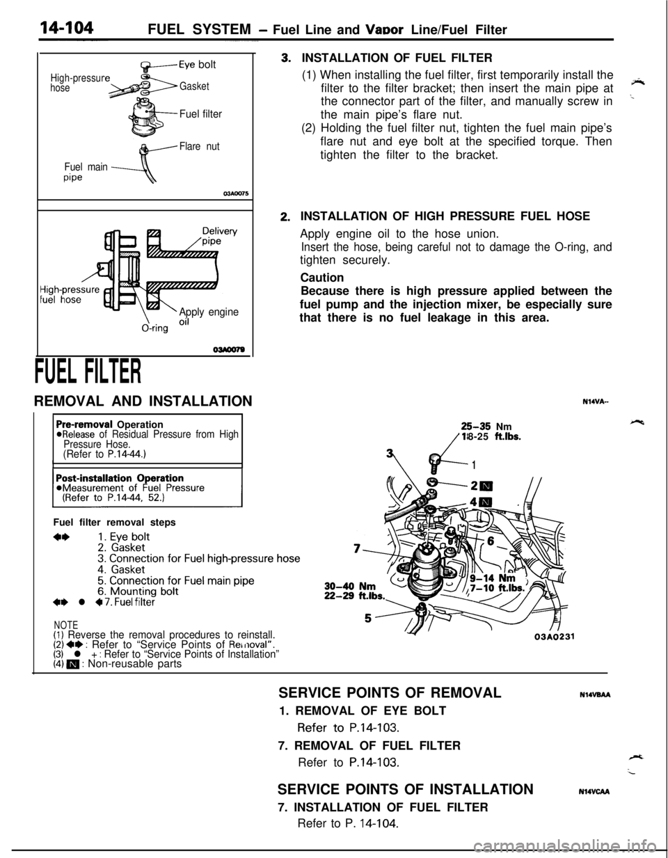
High-pressur
hose
f+-----Eye bolt
Gasket
Fuel filter
Flare nut
Fuel main
pipe
\-Apply engine
&ring Oi’
FUEL FILTERREMOVAL AND INSTALLATION3.2.INSTALLATION OF FUEL FILTER
(1) When installing the fuel filter, first temporarily install the
filter to the filter bracket; then insert the main pipe at
‘*the connector part of the filter, and manually screw in
..the main pipe’s flare nut.
(2) Holding the fuel filter nut, tighten the fuel main pipe’s
flare nut and eye bolt at the specified torque. Then
tighten the filter to the bracket.
Pre-removal Operation@Release of Residual Pressure from High
Pressure Hose.
(Refer to P.14-44.)IIFuel filter removal steps
**1. Eye bolt2. Gasket3. Connection for Fuel high-pressure hose
4. Gasket
5. Connection for Fuel main pipe6. Mounting bolt+e l 4 7. Fuel filter
NOTE(1) Reverse the removal procedures to reinstall.(2) +e : Refer to “Service Points of Removal”.(3) l + : Refer to “Service Points of Installation”(4) m : Non-reusable partsINSTALLATION OF HIGH PRESSURE FUEL HOSE
Apply engine oil to the hose union.
Insert the hose, being careful not to damage the O-ring, andtighten securely.
Caution
Because there is high pressure applied between the
fuel pump and the injection mixer, be especially sure
that there is no fuel leakage in this area.
N14VA-25-35 Nm
18-25
ft.lbs.
vd-
7’
1
Y03A0231SERVICE POINTS OF REMOVAL
NlIVBAA1. REMOVAL OF EYE BOLT
Refer to P.14-103.
7. REMOVAL OF FUEL FILTER
Refer to
P.14-103.SERVICE POINTS OF INSTALLATION
7. INSTALLATION OF FUEL FILTER
Refer to P. 14-104.
N14VCAA
Page 593 of 1216
AUTO-CRUISE CONTROL SYSTEM - service Adjustment ~rocehre~
ACTUATOR INSPECTlCfN
(1) Remove the actuator.
(2) Apply negative pressure to the actuator with
the! &c&mpump and check that the holder moves more than 35
,mm(1.38 in.). In addition, check that there is no change
iii the
position of the holder when negative pressure is main-
tained in that condition.
(3) First install the actuator and then inspect and adjust the
cruise control cable (Refer to
P.14-136.).
I,_1I-35 mm (1.38 in.) or more07AOO52
VEHICLE-SPEED SENSOR INSPECTION
Refer to GROUP 8-Meters and Gauges for checking of vehiclespeed sensor.
ACCELERATOR SWITCH INSPECTIONRefer to GROUP 21 -Troubleshooting.
Page 597 of 1216
, d-a:-;._‘PROPELLER
=. ’SHAFT
CONTENTSNlBAA-
PROPELLER SHAFT........................................4Lubricants......................................................3
2
SPECIAL TOOLS3ServiceSpecifications.................................................................................
TorqueSpecifications...................................2
SPECIFICATIONS.............................................2
TROUBLESHOOTING......................................3
General
Specifications..................................21
Page 598 of 1216

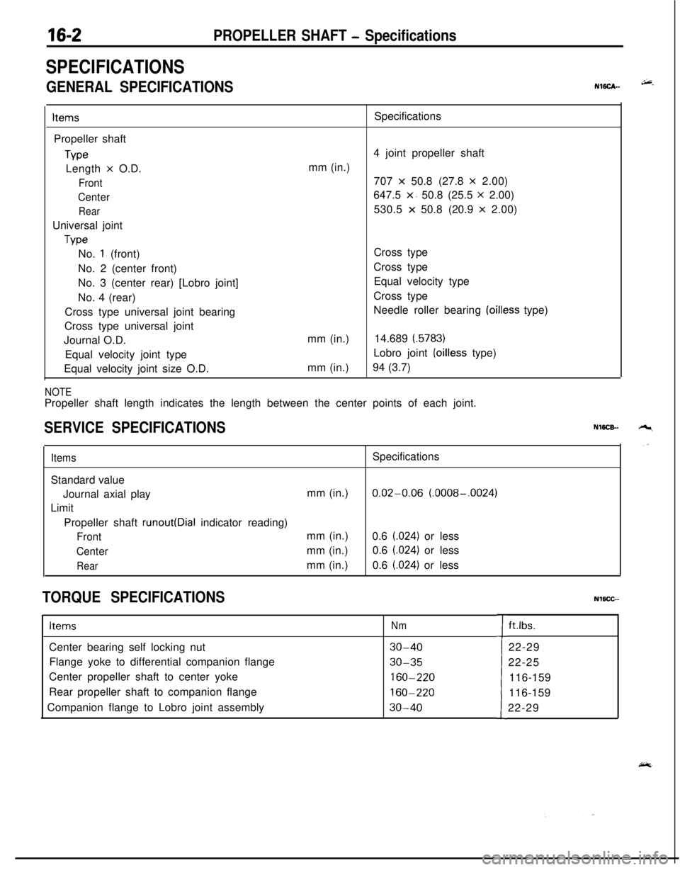
16-2PROPELLER SHAFT - Specifications
SPECIFICATIONS
GENERAL SPECIFICATIONSNWCA--
ItemsPropeller shaft
TypeLength
x O.D.
Front
Center
RearUniversal joint
TypeSpecifications
4 joint propeller shaft
mm (in.)
707
x 50.8 (27.8 x 2.00)
647.5
x. 50.8 (25.5 x 2.00)
530.5
x 50.8 (20.9 x 2.00)
No.
1 (front)
No. 2 (center front)
No. 3 (center rear) [Lobro joint]
No. 4 (rear)
Cross type universal joint bearing
Cross type universal joint
Journal O.D.
Equal velocity joint type
Equal velocity joint size O.D.mm (in.)
mm (in.)Cross type
Cross type
Equal velocity type
Cross type
Needle roller bearing
(oilless type)
14.689
(.5783)Lobro joint
(oilless type)
94 (3.7)
NOTEPropeller shaft length indicates the length between the center points of each joint.
SERVICE SPECIFICATIONSNWCB-
ItemsSpecifications
Standard value
Journal axial playmm (in.)
0.02-0.06 (.0008-.0024)
Limit
Propeller shaft
runout(Dial indicator reading)
Frontmm (in.)
0.6 (.024) or less
Centermm (in.)0.6 (.024) or less
Rearmm (in.)0.6 (.024) or less
TORQUE SPECIFICATIONSNlBCC--
ItemsNmCenter bearing self locking nut
30-40Flange yoke to differential companion flange
30-35Center propeller shaft to center yoke
160-220Rear propeller shaft to companion flange
160-220Companion flange to Lobro joint assembly
30-40tft.lbs.
22-29
22-25
116-159
116-159
22-29
Page 599 of 1216
PROPELLER SHAFT - Specifications/Special Tools/Troubleshooting*(g&a
LUBRICANTS‘) wN$ii%.y,
Items
Sleeve yoke surfaceSpecified lubricant
h +Quafqtity ; ’‘I, ‘. ,b:MOPAR Hypoid Gear
Oil/API classification As required
GL-4 or higher, SAE 75W-85WLobro jointOuter and inner races
assemblyball grooves
Rubber packingLobro joint assembly
inner part
Center bearing front and rear grease
grooves and dust seal lip
Shafts and grease sumps of journal,
dust seal lips and needle bearingsRepair kit grease
Repair kit grease
MOPAR Multi-mileage Lubricant
Part No. 2525035 or equivalentAs required
,.. . ‘*
,^45-55
g(1.59-1.94 oz)As required
SPECIAL TOOLSNlBDA--
TROUBLESHOOTINGNWEAAB
SymptomNoise at start
Noise and vibration
at high speedProbable causeWorn journal bearing
Worn sleeve yoke spline
Loose propeller shaft installation
Unbalanced propeller shaft
Worn journal bearing
Improper snap ring selectionRemedy
Replace
Retighten
ReplaceAdjust the clearance
Page 611 of 1216

1 pq
,s I’
:
REAR
SUSPENSION
LATERAL ROD.................................................11
REAR AXLE HUB............................................14
REARSUSPENSIONASSEMBLY..................5
SERVICE ADJUSTMENT PROCEDURES.......3Rear Hub Rotary-Sliding Resistance
(Torque)Adjustment.....................................4Rear Wheel Alignment Inspection
...............3Wheel Bearing End Play Adjustment
..........3
SHOCKABSORBERASSEMBLY...................8
SPECIAL TOOL................................................3
SPECIFICATIONS.............................................2
GeneralSpecifications..................................2
ServiceSpecifications...................................2Torque Specifications
...................................2
TORSION AXLE AND ARM ASSEMBLY......12
TROUBLESHOOTING......................................3
REARSUSPENSIONASSEMBLY . . . . . . . . . . . . . . . . . .21
SHOCK ABSORBER ASSEMBLY...................32
SERVICE ADJUSTMENT PROCEDURES.......20Rear WheelAlignment
Inspection................20
SPECIAL TOOLS.............................................18
SPECIFICATIONS.............................................16
GeneralSpecifications..................................16
ServiceSpecifications...................................16LTorqueSpecifications...................................17
Lubricant.......................................................17
STABILIZER BAR. . . . . . . . . . . . . . . . . . . . . . . . . . . . . . . . . . . . . . . . . . . . .35
TRAILING ARM. . . . . . . . . . . . . . . . . . . . . . . . . . . . . . . . . . . . . . . . . . . . . . .28
TROUBLESHOOTING......................................19
UPPER AND LOWER ARM............................25
CONTENTSN17AA-
Page 620 of 1216
L
)il spri
12A0049
REAR SUSPENSION - Shock Absorber Assembly
SERVICE POINTS OF REASSEMBLYNl7QPA2
11. INSTALLATION OF COIL SPRING(1) Use the special tool
(L-4514) to compress the coil ,“3”spring and insert it in the shock absorber.
(2) Align the edge of the coil spring to the position of the
shock absorber spring seat as shown.
Cup assembly
1
Dd cover
IBracket assembly
1 Shock absorber lower bushing12R01409. INSTALLATION OF DUST
COVEW8. CUP ASSEMBLY
As shown in the illustration, fit the dust cover to the cup
assembly.
4. INSTALLATION OF BRACKET ASSEMBLY/l. PISTON
ROD TIGHTENING NUT(1) With the position of the bracket assembly as shown in
the figure, tighten the tightening nut to the specified*c,
torque.
(2)Install the coil spring so that the lower edge fits into thespring seat groove and the upper edge fits into the
spring pad groove, then remove the special tool
(L-4514).
Page 659 of 1216

STEERING - Service Adjustment Procedures < Power Steering >194113AO29313AO290
STEERING WHEEL CENTERINGNlSFIYAFCenter the steering wheel in the same way as the manual
steering. (Refer to P.19-8.1
STATIONARY STEERING EFFORT CHECKNlSFFAI
1. With the vehicle stopped on a flat, paved surface, turn the
steering wheel to the straight ahead position.
2. Start the engine and set it to 1,000 + 100 rpm.
Caution
After checking the engine rpm., there must be a return to
the standard idling rpm.3. Attach a spring balance to the outer circumference of the
steering wheel and measure the steering force required to
turn the steering wheel from the straight ahead position to
the left and right (within a range of 1.5 turns).
Also check to be sure that there is no significant fluctuationof the required steering force.
Standard value:
Steering effort37
N (8 lbs.) or less
Fluctuation allowance6 N (1.3 Iljs.)‘or less:...
STEERING WHEEL RETURN TO CENTER CHE$$$aETo make this test, conduct a road test and check as follows.
1.Make both gradual and sudden turns and check the steering
“feeling” to be sure that there is no difference in the steeringforce required and the wheel return between left and right
turns.2. At a speed of 35 km/h
(22 mph), turn the steering wheel
90°, and release the steering wheel after 1 or 2 seconds.
If the steering wheel then returns
70” or more, the return
can be judged to the satisfactory.
NOTE
There will be a momentary feeling of “heaviness” when thewheel is turned quickly, but this is not abnormal. (This is
because the oil pump discharge amount is especially apt to
be insufficient during idling.
1