Page 859 of 1216

AUTOMATIC TRANSAXLE - Specifi6atiorisPart name
Spacer
(W4A33)(for adjustment of drive bevel gear train
preload)Spacer
(W4A33)(for adjustment of driven bevel gear train
preload)
Spacer (W4A33)
~for adjustment of driven bevel gear trainxeload)
spacer (W4A33)for adjustment of driven bevel gear mount)
Thickness1.64
(.0646)1.67
(.0657)1.70
(.0669)1.73 (0681)
1.76 l.0693)1.79
(.0705)
1.82(0717)
1.85
(.0728)
1.19
(.0469)
1.22(0480)
1.25(.0492)
1.28(0504)
1.31(0516)
1.34(0528)
1.37(.0539)
1.40(0551)
1.43(.0563)
1.46(0575)
1.49(.0587)
1.52(0598)
1.55(0610)
1.58(0622)
1.61(0634)
1.64(0646)
1.67(.0657)
1.70(.0669)
1.73(0681)
1.76(.0693)
1.79
(.0705)
1.82(0717)
1.85(0728)
1.88(.0740)
1.91(.0752)
1.94
(.0764)
0.13(0051)
0.16
(.0063)0.19 (0075)
0.22(0087)
0.25(.0098)0.28
(.Ol 10)0.31(0122)
0.34(0134)
0.37(0146)
0.40(.0517)
0.43(.0169)
0.46(0181)
0.49(.0193)
0.52(0205)mm (in.) Identification mark ‘Part
‘);ilb. I”
B64MD724335
B67MD724336
B70MD724337
B73M~724338
B76MD724339
B79MD724340882
MD724341
B85MD724342
19MD7261 72
22
MD722081
25MD722082
28MD722683
31MD722084
34MD722085
37MD722086
40MD722087
43MD722088
46MD722089
49MD7228090
52
.MD722091
55MD722092
58MD722093
61MD722694
64MD722095
67MD722096
70MD722097
73MD722098
76MD722099
79MD7221 00
82MD7221 01’
85MD7221 02
88
MD7221 03
91MD7221 04
94
MD7221 05
13MD720353
16MD720354
j19MD72035522M~$,gjg~~
25,:!,MD’ly&““$28””
“’ti&2&58
e>I3 1hbf,&$&
34,‘IMbf2tiyo
37MD720361
40
MD720362
43
MD726363
46MD720364
49MD720365
52MD720366
Page 912 of 1216

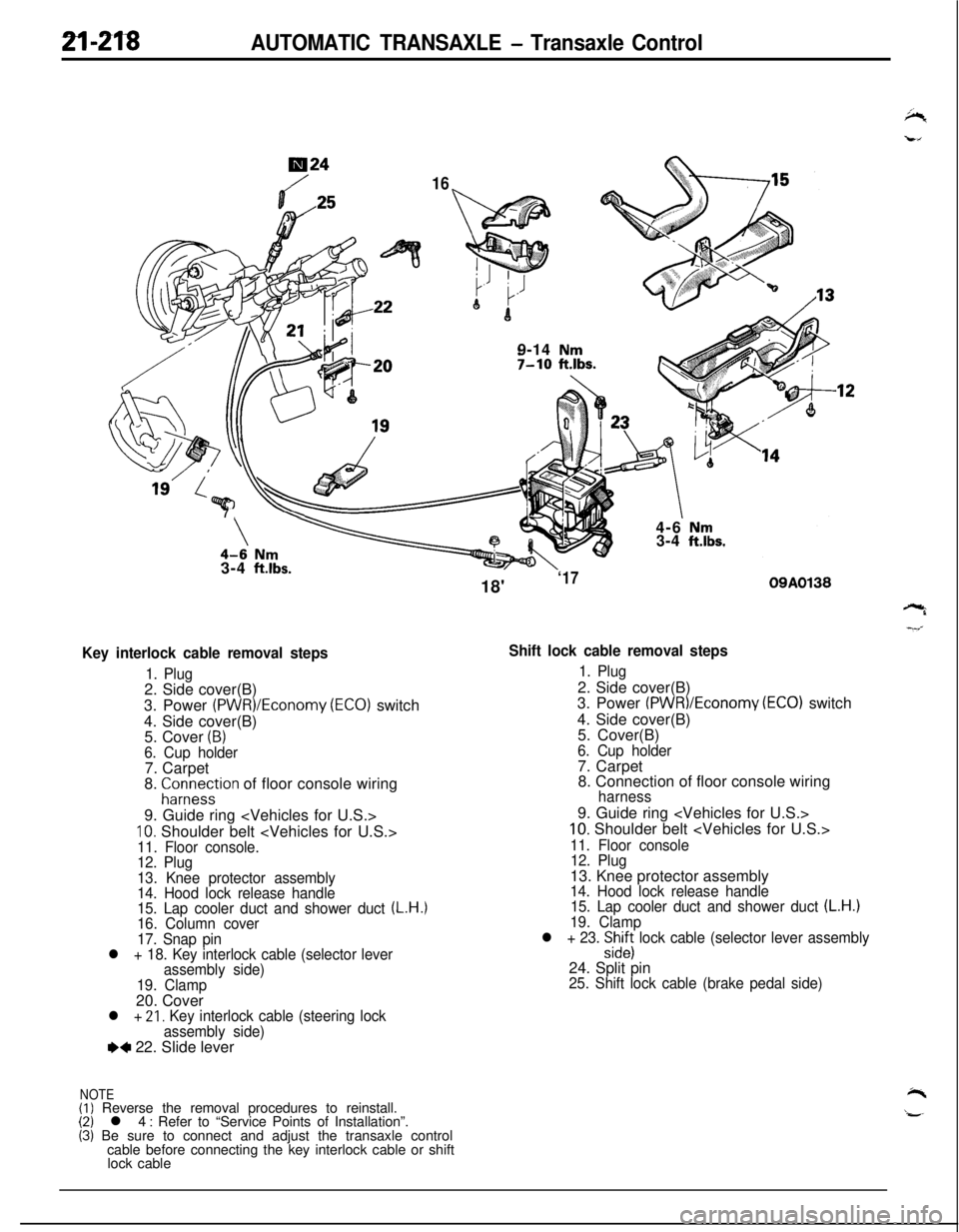
2l-218AUTOMATIC TRANSAXLE - Transaxle Control
724
169-14
Nm7-10 ftlbs.7
\\4-6 Nm3-4 ft.lbs.3-4
ft.lbs.
Key interlock cable removal steps
1. Plug2. Side cover(B)
3. Power
(PWR)/Economy (ECO) switch
4. Side cover(B)
5. Cover
(B)6. Cup holder7. Carpet
8.
;ir;eystion of floor console wiring
9. Guide ring
10. Shoulder belt 11. Floor console.
12. Plug
13. Knee protector assembly
14. Hood lock release handle
15. Lap cooler duct and shower duct
(L.H.)16. Column cover
17. Snap pin
l + 18. Key interlock cable (selector lever
assembly side)
19. Clamp20. Cover
l + 21, Key interlock cable (steering lock
assembly side)
e+ 22. Slide lever
NOTE(I) Reverse the removal procedures to reinstall.(2) l 4 : Refer to “Service Points of Installation”.(3) Be sure to connect and adjust the transaxle control
cable before connecting the key interlock cable or shift
lock cable18'
‘1709A0138
Shift lock cable removal steps
1. Plug2. Side cover(B)
3. Power
(PWR)/Economv (EC01 switch
4. Side cover(B)
’5. Cover(B)
6. Cup holder7. Carpet
8. Connection of floor console wiring
harness9. Guide ring
10. Shoulder belt
11. Floor console
12. Plug13. Knee protector assembly
14. Hood lock release handle
15. Lap cooler duct and shower duct (L.H.)19. Clamp
l + 23. :izs lock cable (selector lever assembly24. Split pin
25. Shift lock cable (brake pedal side)
Page 918 of 1216

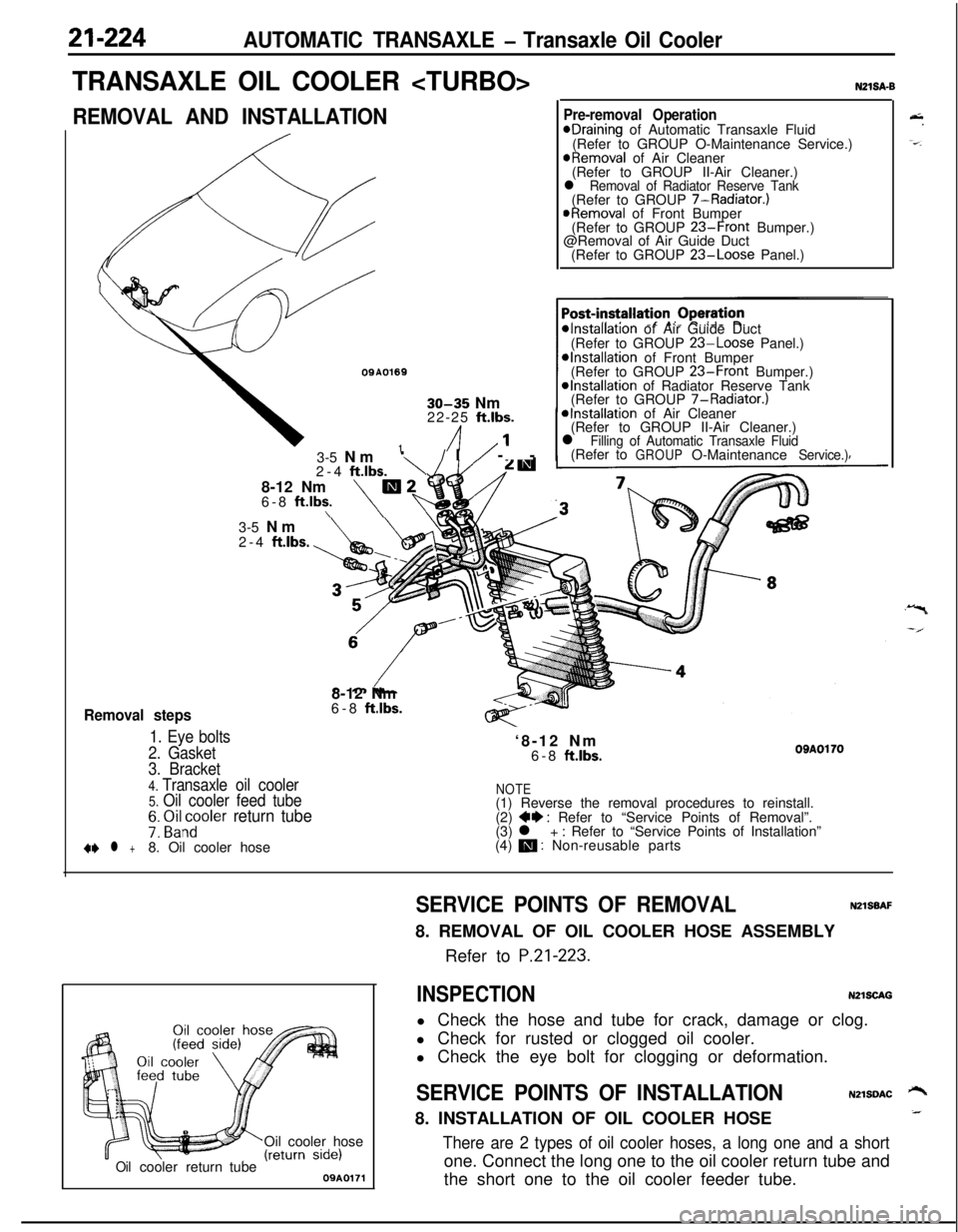
21-224AUTOMATIC TRANSAXLE - Transaxle Oil Cooler
TRANSAXLE OIL COOLER
REMOVAL AND INSTALLATION
OQA01691
30-35 Nm
22-25 ft.lbs.
/I1’
Removal steps
1. Eye bolts
2. Gasket3-5 Nm
‘\/I/ --
2-4
ftlbs.8-12 Nm
m26-8 ft.lbs.\\
N21SA-B
Pre-removal OperationeDraining of Automatic Transaxle Fluid
(Refer to GROUP O-Maintenance Service.)
@Removal of Air Cleaner
(Refer to GROUP II-Air Cleaner.)
l Removal of Radiator Reserve Tank(Refer to GROUP 7-Radiator.)
@Removal of Front Bumper
(Refer to GROUP 23-Front Bumper.)
@Removal of Air Guide Duct
(Refer to GROUP
23-Loose Panel.)
*Installation of Air Guide Duct
(Refer to GROUP 23-Loose Panel.)*Installation of Front Bumper
(Refer to GROUP 23-Front Bumper.)@Installation of Radiator Reserve Tank
(Refer to GROUP 7-Radiator.)
*Installation of Air Cleaner
(Refer to GROUP II-Air Cleaner.)
l Filling of Automatic Transaxle Fluid(Refer toGROUPO-MaintenanceService.)3-5 Nm
2-4
ftlbs.8-12 Nm
6-8
ft.lbs.‘8-12 Nm
6-8
ftlbs.OBAOl703. Bracket
4. Transaxle oil cooler5. Oil cooler feed tubeNOTE(1) Reverse the removal procedures to reinstall.
7: ~i&~oler return tube(2) ++ : Refer to “Service Points of Removal”.
(3) l + : Refer to “Service Points of Installation”
+e l +8. Oil cooler hose(4) m : Non-reusable parts
Oil cooler hose
Oilcoolerreturn tube09A0171
&.
-=-.
SERVICE POINTS OF REMOVALNZlSBAF8. REMOVAL OF OIL COOLER HOSE ASSEMBLY
Refer to
P.21-223.
INSPECTIONN2lSCAGl Check the hose and tube for crack, damage or clog.
l Check for rusted or clogged oil cooler.
l Check the eye bolt for clogging or deformation.
SERVICE POINTS OF INSTALLATIONN2lSDAC ‘-+8. INSTALLATION OF OIL COOLER HOSE_
There are 2 types of oil cooler hoses, a long one and a shortone. Connect the long one to the oil cooler return tube and
the short one to the oil cooler feeder tube.