Page 1066 of 1146

52B-56SUPPLEMENTAL RESTRAINT SYSTEM (SRS) - front lwtact sensors
INDIVIDUAL COMPONENT SERVICEIf the SRS components are to be removed or replaced as a result of maintenance, troubleshooting, etc.,
follow each procedure
(P.52B-56 - P.52B-68).L++(
Caution
1.SW components should not be subjected to heat over 93°C (2OO”F), so remove the front impactsensors, SRS diagnosis unit and air bag module and clock spring before drying or baking the
vehicle after painting. Recheck SRS system operability after re-installing them.
2.If the SRS components are removed for the purpose of check, sheet metal repair, painting, etc.,they should be stored in a clean, dry place until they are reinstalled.
FRONT IMPACT SENSORS
Caution1. Never repair or disassemble a front impact
sensor. If faulty, replace it.
2.Handle the front impact sensors very careful-
ly, taking care not to drop them or otherwise
subject them to impact. If a sensor is seen tobe dented, cracked, deformed or rusted,
replace it with a new one.
3.Replace sensors with new ones after the air
bag has deployed.
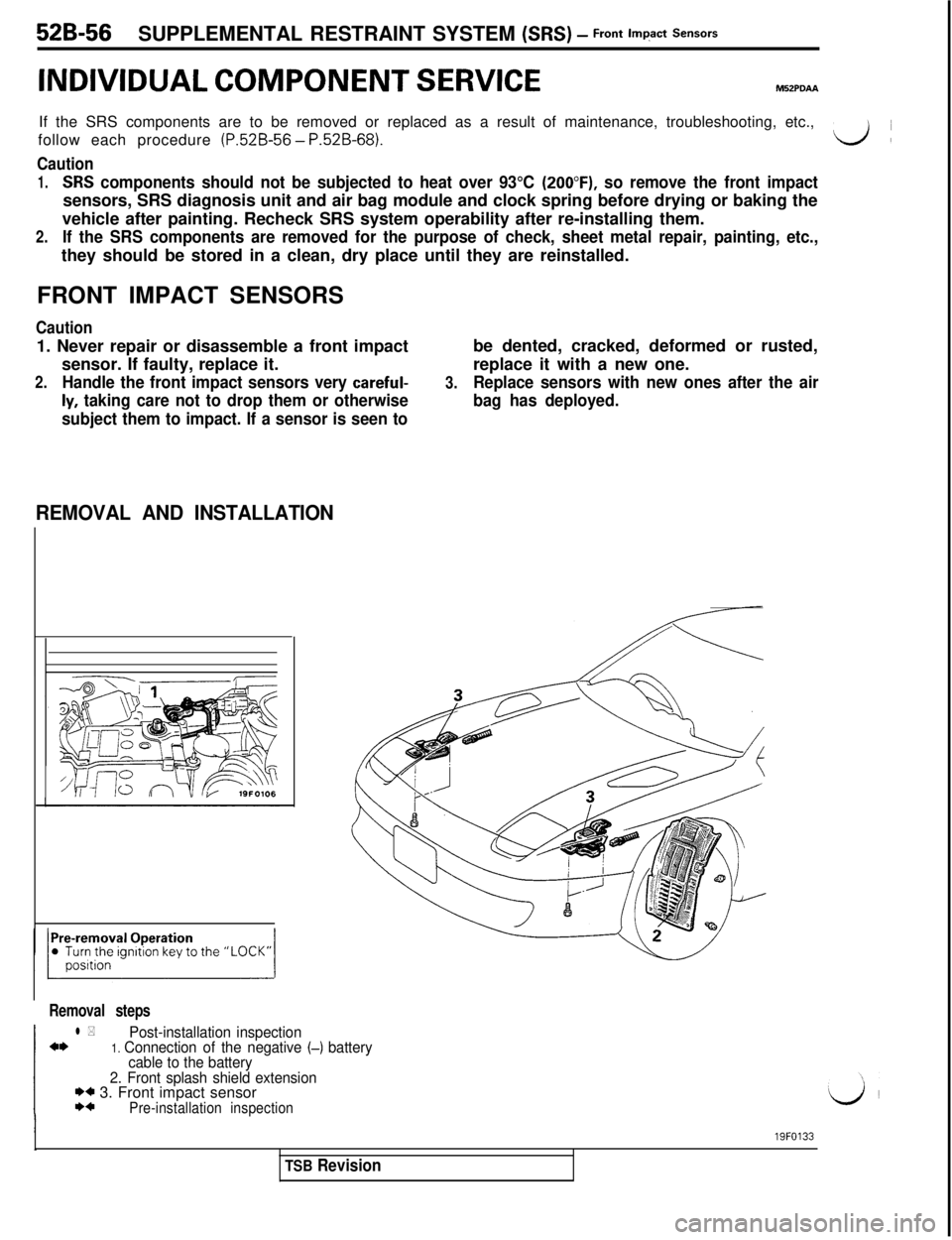
REMOVAL AND INSTALLATION
Removal steps
l *Post-installation inspectiona*1. Connection of the negative (-) battery
cable to the battery
2. Front splash shield extension
I)* 3. Front impact sensorI)*Pre-installation inspection
I19FO133
TSB Revision
Page 1083 of 1146

55-1
HEATER, AIR
CONDITIONER
AND VENTILATION
CONTENTSM55AA- -
HEATERS AND AIR CONDITIONING................3HEATER UNIT*........................................................................22
SPECIFICATIONS
....................................................................3REFRIGERANT LINE................................................................35General Specifications
........................................................3RESISTOR................................................................................20Lubricants
............................................................................4SAFETY PRECAUTIONS........................................................9Sealant and Adhesive............................................................4
Service Specifications3SERVICE ADJUSTMENT PROCEDURES............................10........................................................
SPECIAL TOOLS4Charging Procedures............................................................11
i
........................................................................Charging the Refrigerant....................................................12Compressor Drive Belt Adjustment....................................11
HEATERS AND MANUAL AIR CONDITIONER5Compressor Noise................................................................16
................................................16
AIR CONDITIONER SWITCH................................................21Handling Tubing andFittings
Idle-up Operation Check....................................................17
BELT LOCK CONTROLLER20Performance Test................................................................15....................................................
BLOWER ASSEMBLYPower Relay Check............................................................17............................................................23Refrigerant Leak Repair Procedure....................................15COMPRESSOR........................................................................
27TestProcedures....................................................................10
CONDENSER AND CONDENSER FAN MOTOR................33TROUBLESHOOTING............................................................5
ENGINE COOLANT TEMPERATURE SWITCH....................
39VENTILATORS (AIR INLET AND AIR OUTLET)................38
EVAPORATOR
........................................................................
25VENTILATORS (INSTRUMENT PANEL)*............................36
HEATER CONTROL ASSEMBLY*
........................................18CONTINUED ON NEXT PAGE
SUPPLEMENTAL RESTRAINT SYSTEM (SRS)
(1)A Supplemental Restraint System (SRS), which uses a driver-side air bag, has been installed in the 3000GT.(2)The SRS includes the following components: impact sensors, SRS diagnosis unit: SRS warning light, air bagmodule, clock spring, interconnecting wiring. Other SRS-related components (that may have to be
removed/installed in connection with SRS service or maintenance) are indicated in the table of contents byan asterisk (*).
WARNING!(1)Improper service or maintenance of any component of the SRS, or any SRS-related component, can lead to
personal injury or death to service personnel (from inadvertent firing of the air bag) or to the driver (fromrendering the
SRS inoperative).(2) Service or maintenance of any SRS component or SRS-related component must be performed only at anauthorized MITSUBISHI dealer.
(3) MITSUBISHI dealer personnel must thoroughly review this manual, and especially its GROUP 52B
-Supplemental Restraint System (SRS), before beginning any service or maintenance of any component of theSRS or any SRS-related component.
Page 1121 of 1146
Pre-removal and Post-installation Operationl Draining and Refilling of Engine Coolant(Refer to GROUP 00 - Maintenance Service.)
1. Engine coolant temperature switchHEATERS AND MANUAL AIR CONDITIONER
- Z!&E%Ltch55-39
ENGINE COOLANT TEMPERATURE SWITCH
M55xA- -
L
REMOVAL AND INSTALLATIONSealant: 3M Nut Locking Part No.
4171 or equivalent
BQQQQQ20A0199INSPECTION
MSSXCAAENGINE COOLANT TEMPERATURE SWITCH
(ALWAYS-
CLOSED TYPE CHECK)
(1) Immerse the engine coolant temperature switch in oil and
heat by a gas stove or similar method so as to increase the
oil temperature.(2) Check to be sure that the engine coolant temperature
switch is switched OFF when the oil temperature reaches
the standard value.Standard value: 112
- 118°C (233 - 244°F)
CautionUse engine oil for this test; stir it well while heating,
and do not heat more than necessary.
1 TSB Revision