1991 MITSUBISHI 3000GT maintenance
[x] Cancel search: maintenancePage 817 of 1146

36-1
PARKING
BRAKES
CONTENTSM36AA-.
PARKINGBRAKE. . . . . . . . . . . . . . . . . . . . . . . . . . . . . . . . . . . . . . . . . . . . . . . .8SPECIAL TOOLS . .._.._.............................................
PARKING BRAKE LEVER AND PARKINGSPECIFICATIONS................................................
BRAKE CABLE*....................................................5General Specifications....................................
SERVICE ADJUSTMENT PROCEDURES4Lubricants....................................................................Parking Brake Lever Stroke Check4Sealants
andAdhesives....................................................Parking Brake Switch Check
............................4Service Specifications....................................
TROUBLESHOOTING........................................
i
SUPPLEMENTAL RESTRAINT SYSTEM (SRS)
(1)A Supplemental Restraint System (SRS), which uses a driver-side air bag, has been installed in the 3000GT.(2)The SRS includes the following components: impact sensors, SRS diagnosis unit: SRS warning light, air bagmodule, clock spring, interconnecting wiring. Other SRS-related components (that may have to be
removed/installed in connection with SRS service or maintenance) are indicated in the table of contents byan asterisk (*).
WARNING!(1)Improper service or maintenance of any component of the SRS, or any SRS-related component, can lead to
personal injury or death to service personnel (from inadvertent firing of the air bag) or to the driver (fromrendering the SRS inoperative).(2) Service or maintenance of any SRS component or SRS-related component must be performed only at an
authorized MITSUBISHI dealer.(3) MITSUBISHI dealer personnel must thoroughly review this manual, and especially its GROUP 52B
-Supplemental Restraint System (SRS), before beginning any service or maintenance of any component of theSRS or any SRS-related component.
u
I
Page 829 of 1146

37A-1
STEERING
CONTENTSM37AA-A
POWER STEERING GEAR BOX*....................17Steering Wheel Return to Center
Check................................................................8
POWER STEERING HOSES................................32Tie Rod End Ball Joint Startinq Torque
POWER STEERING OIL PUMP. .._....................28Check. . . . . . . . .._.............................. r . . . . . . . . ..I . . . . . .6Tie Rod End Ball Joint Variation Check
SERVICE ADJUSTMENT PROCEDURES5(Shaft direction)................................................5........
Bleeding............................................................10V-Belt Tension Check........................................8
Fluid Level Check............................................9SPECIAL TOOLS....................................................3Fluid Replacement
............................................9
/
bOil Pressure Switch Check
SPECIFICATIONS2............................12................................................Oil Pump Pressure Test
....................................1 1General Specifications....................................2Stationary Steering Effort Check
....................8Lubricants............................................................3Steering Angle Check
5Sealant and Adhesives....................................3........................................Steering Wheel Centering
6Service Specifications....................................2................................Steering Wheel Free Play Check
....................5STEERING WHEEL AND SHAFT*....................13
SUPPLEMENTAL RESTRAINT SYSTEM (SRS)
(1)A Supplemental Restraint System (SRS), which uses a driver-side air bag, has been installed in the 3000GT.(2)The SRS includes the following components: impact sensors, SRS diagnosis unit: SRS warning light, air bagmodule, clock spring, interconnecting wiring. Other SRS-related components (that may have to be
removed/installed in connection with SRS service or maintenance) are indicated in the table of contents byan asterisk (*).
WARNING!(I)Improper service or maintenance of any component of the SRS, or any SRS-related component, can lead to
personal injury or death to service personnel (from inadvertent firing of the air bag) or to the driver (from
rendering the SRS inoperative).
(2) Service or maintenance of any SRS component or SRS-related component must be performed only at an
authorized MITSUBISHI dealer.(3) MITSUBISHI dealer personnel must thoroughly review this manual, and especially its GROUP 52B
-Supplemental Restraint System (SRS), before beginning any service or maintenance of any component of theSRS or any SRS-related component.
Page 873 of 1146

42-1
BODY
CONTENTSM42AA- -
CENTER PILLAR GLASS........................................................32
CENTRAL DOOR LOCKING SYSTEM
................................55
DOOR ASSEMBLY....................................................................40
DOOR GLASS AND REGULATOR
........................................42
DOOR HANDLE AND LATCH
................................................54
DOOR TRIM AND WATERPROOF FILM
............................41
DRIP LINE WEATHERSTRIP....................................................65
ENGINE HOOD........................................................................18
FENDER*....................................................................................23
FUEL TANK FILLER DOOR
....................................................22
LIFTGATE....................................................................................20
LIFTGATE GLASS....................................................................37
LOOSE PANEL
........................................................................24
POWER WINDOW
....................................................................43
QUARTER WINDOW GLASS
................................................33SERVICE ADJUSTMENT PROCEDURES
............................
Door Adjustment................................................................Door inside Handle Play Check............................................Door Window Glass Adjustment........................................Floor Pan inspection............................................................Fuel Filler Door Adjustment................................................Hood Adjustment................................................................Liftgate Adjustment............................................................
SPECIAL TOOLS........................................................................
SPECIFICATIONS....................................................................
General Specifications........................................................Sealants and Adhesives........................................................
ServiceSpecifications........................................................
TROUBLESHOOTING............................................................
WINDOW GLASS....................................................................
WINDSHIELD............................................................................
13
14
16
14
17
14
13
13
4
2
2
3
3
5
25
28
SUPPLEMENTAL RESTRAINT SYSTEM (SRS)
(1)A Supplemental Restraint System (SRS), which uses a driver-side air bag, has been installed in the 3000GT.(2)The SRS includes the following components: impact sensors, SRS diagnosis unit: SRS warning light, air bagmodule, clock spring, interconnecting wiring. Other SRS-related components (that may have to be
removed/installed in connection with SRS service or maintenance) are indicated in the table of contents byan asterisk (*).
WARNING!(1)Improper service or maintenance of any component of the SRS, or any SRS-related component, can lead to
personal injury or death to service personnel (from inadvertent firing of the air bag) or to the driver (from
rendering the SRS inoperative).
(2) Service or maintenance of any SRS component or SRS-related component must be performed only at an
authorized MITSUBISHI dealer.(3) MITSUBISHI dealer personnel must thoroughly review this manual, and especially its GROUP 52B
-Supplemental Restraint System (SRS), before beginning any service or maintenance of any component of the
SRS or any SRS-related component.
Page 979 of 1146

INTERIORCONTENTSNWAA-A~
FLOOR CONSOLE*
____....._.........__._..._......_..._...... 11
REAR SEAT . .._._____..______....____.._.._._..___.._._____.....___....24
FRONT SEAT*
. . . . . . . . . . . . . . . . . . . . . . . . . . . . . . . . . . . . . . . . .18SEAT BELT*. . . . . . . . . . . . . . . . . . . . . . . . . . . . . . . . . . . . . . . . . . . . . . . . . . . . . . . .25IHEADLINING
. . . . . . . . . . . . . . . . . . . . . . . . . . . . . . . . . . . . . . . . . . . . . . . . . . . . . . . .17TRIMS. . . . . . . . . . . . . . . . . . . . . . . . . . . . . . . . . . . . . . . . . . . . . . . . . . . . . . . . . . . . . . . . . . . .12INSTRUMENT PANEL*
. . . . . . . . . . . . . . . . . . . . . . . . . . . . . . . . . . . .8TROUBLESHOOTING. . . . . . . . . . . . . . . . . . . . . .
i
SUPPLEMENTAL RESTRAINT SYSTEM (SRS)
(1)A Supplemental Restraint System (SRS), which uses a driver-side air bag, has been installed in the 3000GT.(2)The SRS includes the following components: impact sensors, SRS diagnosis unit: SRS warning light, air bagmodule, clock spring, interconnecting wiring. Other SRS-related components, (that may have to beremoved/installed in connection with SRS service or maintenance) are indicated in the table of contents byan asterisk (*).
WARNING!(I)Improper service or maintenance of any component of the SRS, or any SRS-related component, can lead topersonal injury or death to service personnel (from inadvertent firing of the air bag) or to the driver (fromrendering the SRS inoperative).(2) Service or maintenance of any SRS component or SRS-related component must be performed only at anauthorized MITSUBISHI dealer.(3) MITSUBISHI dealer personnel must thoroughly review this manual, and especially its GROUP 52B -Supplemental Restraint System (SRS), before beginning any service or maintenance of any component of theSRS or any SRS-related component.
2I
Page 1011 of 1146

528-l
L’ SUPPLEMENTAL
RESTRAINT
SYSTEM (SRS)
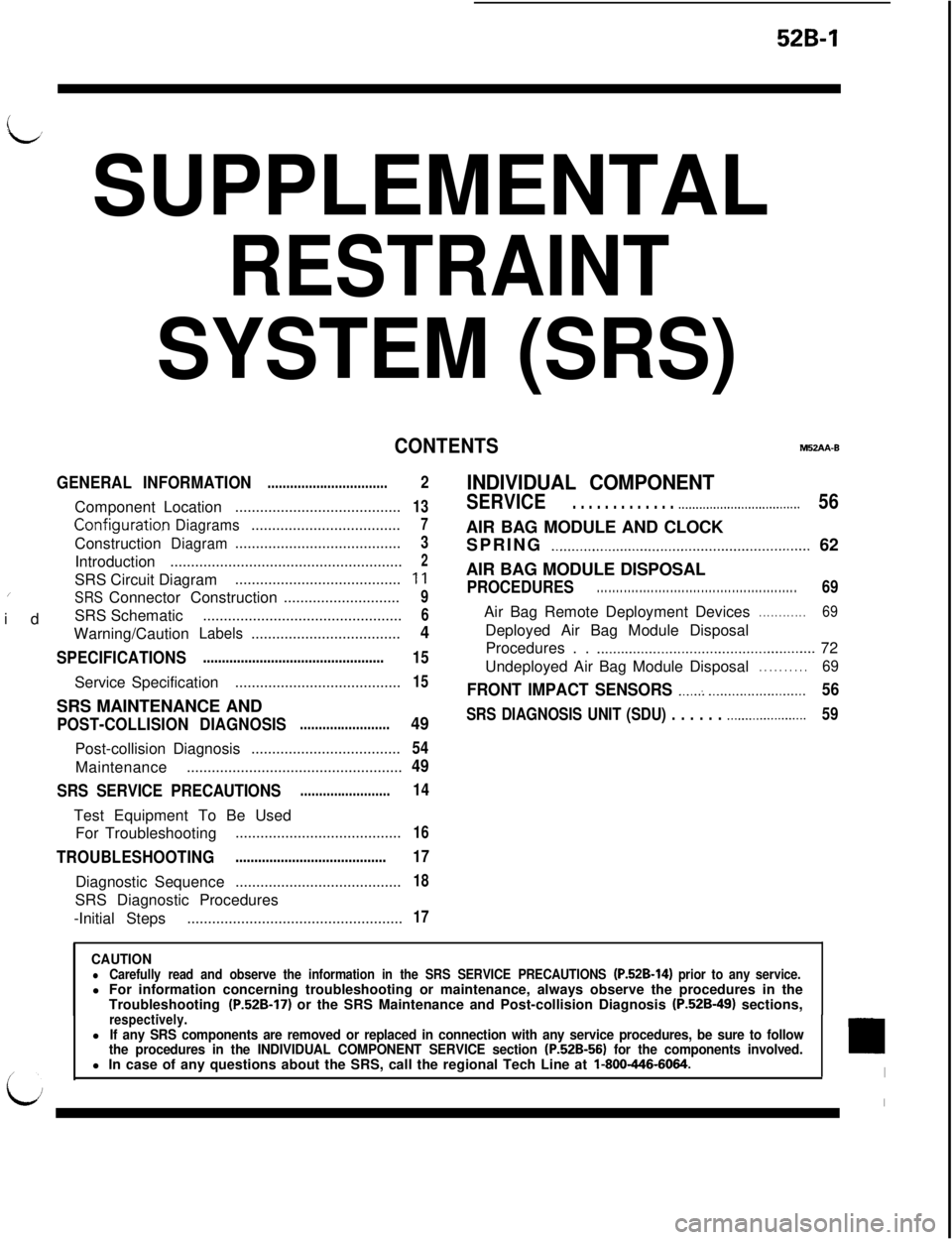
CONTENTSM52AA-B
GENERAL INFORMATION
................................ComponentLocation
........................................
Configurati0.nDiagrams....................................Construction
Diagram........................................Introduction
........................................................SRS Circuit Diagram
......................................../idSRSConnector Construction............................SRS Schematic
................................................Warning/Caution
Labels....................................
SPECIFICATIONS................................................ServiceSpecification
........................................SRS MAINTENANCE AND
POST-COLLISION DIAGNOSIS........................Post-collisionDiagnosis
....................................Maintenance
....................................................
SRS SERVICE PRECAUTIONS........................Test Equipment To Be Used
For Troubleshooting
........................................
TROUBLESHOOTING........................................DiagnosticSequence
........................................SRS Diagnostic Procedures
-Initial Steps
....................................................
2
13
7
3
2
11
9
6
4
15
15
49
54
49
14
16
17
18
17
INDIVIDUAL COMPONENT
SERVICE. . . . . . . . . . . . . .._................................56AIR BAG MODULE AND CLOCK
SPRING
._..........._......................._.........._............... 62
AIR BAG MODULE DISPOSAL
PROCEDURES. . . . . . . . . . . . . . . . . . . . . . . . . . . . . . . . . . . . . . . . . . . . . . . . . . . .69Air Bag Remote Deployment Devices
. . . . . . . . . . . .69Deployed Air Bag Module Disposal
Procedures . .
.._..........._....................................... 72
Undeployed Air Bag Module Disposal
. . . . . . . . . .69
FRONT IMPACT SENSORS ._....: _._..._..................56
SRS DIAGNOSIS UNIT (SDU) . . . . . . .._...................59
CAUTIONlCarefully read and observe the information in the SRS SERVICE PRECAUTIONS (P.52B-14) prior to any service.l For information concerning troubleshooting or maintenance, always observe the procedures in the
Troubleshooting
(P.52B-17) or the SRS Maintenance and Post-collision Diagnosis (P.52B-49) sections,_respectively.lIf any SRS components are removed or replaced in connection with any service procedures, be sure to follow
the procedures in the INDIVIDUAL COMPONENT SERVICE section (P.52B-56) for the components involved.l In case of any questions about the SRS, call the regional Tech Line at l-800-446-6064.
Page 1059 of 1146

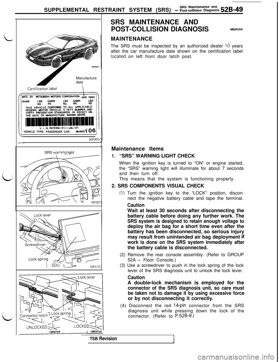
SUPPLEMENTAL RESTRAINT SYSTEM (SRS) - Z~-%Z%&Z% 528-49Manufacture
date
IVEHICLE TYPE: PASSENGER CAR
MU9001/
OOFOOOlSRS
warnmq light- -SDU’
t>19FOlO:SRS MAINTENANCE AND
POST-COLLISION DIAGNOSIS
M52PCAAMAINTENANCE
The SRS must be inspected by an authorized dealer
10 years
after the car manufacture date shown on the certification label
located on left front door latch post.
Maintenance Items
1.“SRS” WARNING LIGHT CHECK
When the ignition key is turned to “ON” or engine started,
the “SRS” warning light will illuminate for about 7 seconds
and then turn off.
This means that the system is functioning properly.
2. SRS COMPONENTS VISUAL CHECK
(1) Turn the ignition key to the “LOCK” position, discon-
nect the negative battery cable and tape the terminal.
CautionWait at least 30 seconds after disconnecting the
battery cable before doing any further work. The
SRS system is designed to retain enough voltage todeploy the air bag for a short time even after the
battery has been disconnected, so serious injury
may result from unintended air bag deployment
if
work is done on the SRS system immediately afterthe battery cable is disconnected.
(2) Remove the rear console assembly. (Refer to GROUP
52A
- Floor Console.)
(3) Use a screwdriver to push in the lock spring of the lock
lever of the SRS diagnosis unit to unlock the lock lever.
CautionA double-lock mechanism is employed for the
connector of the SRS diagnosis unit, so care must
be taken not to damage it by using excessive forceor by not disconnecting it correctly.
(4) Disconnect the red
14-pin connector from the SRS
diagnosis unit while pressing down the lock of the
connector. (Refer to
P.52B-9.)
13R0721113R0722
TSB Revision
Page 1061 of 1146

SRS Maintenance and
SUPPLEMENTAL RESTRAINT SYSTEM (SRS) - Post-coltision Diagnosis 52B-51
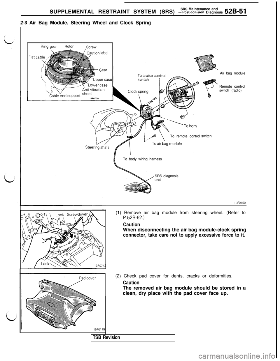
2-3 Air Bag Module, Steering Wheel and Clock Spring
Rtng gearRotor
Screw
3at ca
To remote controlswitchAir bag module
Remote control
switch (radio)
To body wiring harness
SRS diagnosisunit
19FO150
19FO119(1) Remove air bag module from steering wheel. (Refer to
P.52B-62.)
CautionWhen disconnecting the air bag module-clock spring
connector, take care not to apply excessive force to it.(2) Check pad cover for dents, cracks or deformities.
CautionThe removed air bag module should be stored in a
clean, dry place with the pad cover face up.
1 TSB Revision
Page 1063 of 1146

SRS Maintenance and
SUPPLEMENTAL RESTRAINT SYSTEM (SRS) - Post-collision Diagnosis 52B-53
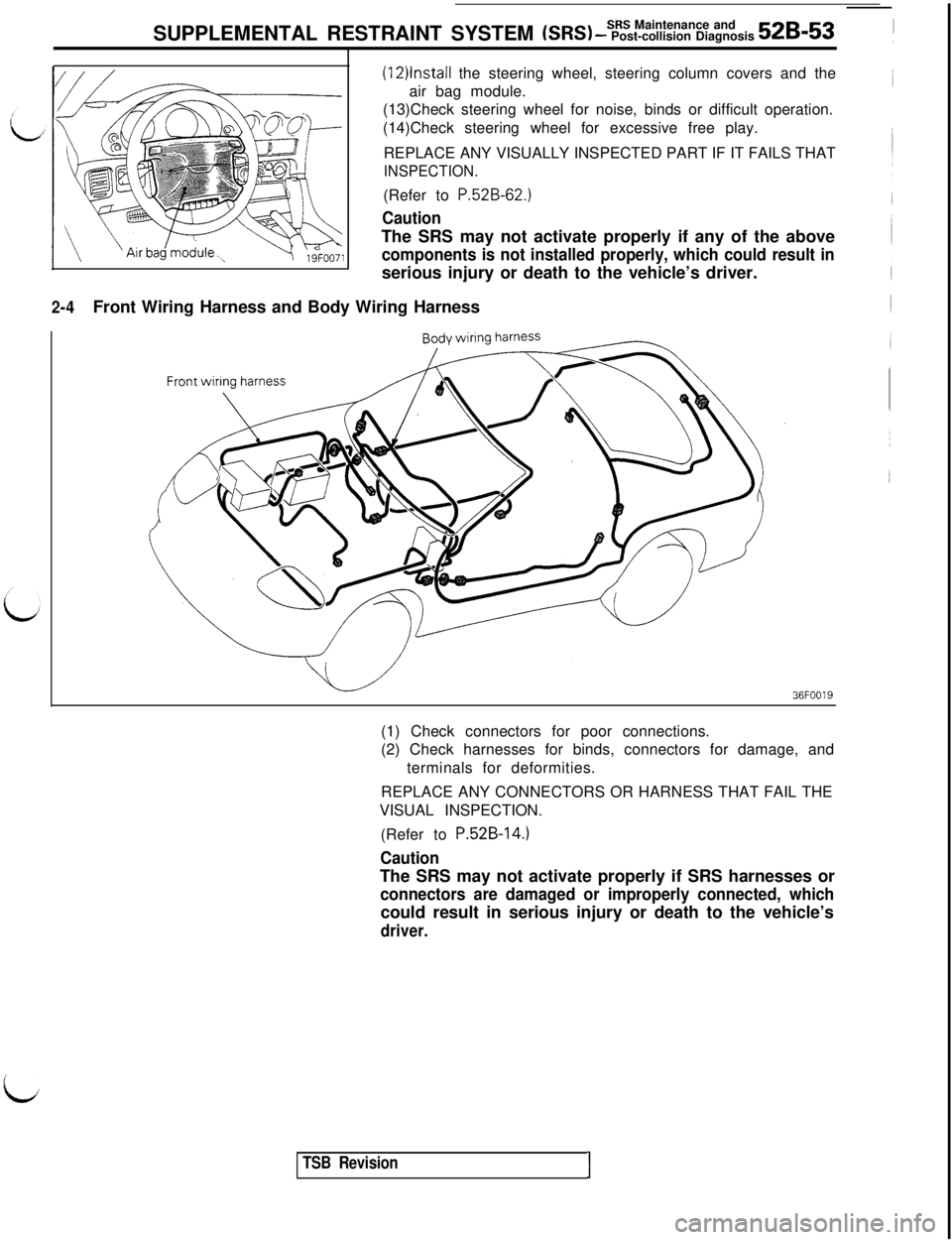
2-4Front Wiring Harness and Body Wiring Harness
(12)lnstall the steering wheel, steering column covers and the
air bag module.
(13)Check steering wheel for noise, binds or difficult operation.
(14)Check steering wheel for excessive free play.
REPLACE ANY VISUALLY INSPECTED PART IF IT FAILS THAT
INSPECTION.(Refer to
P.52B-62.)
CautionThe SRS may not activate properly if any of the above
components is not installed properly, which could result inserious injury or death to the vehicle’s driver.
36FOO19(1) Check connectors for poor connections.
(2) Check harnesses for binds, connectors for damage, and
terminals for deformities.
REPLACE ANY CONNECTORS OR HARNESS THAT FAIL THE
VISUAL INSPECTION.
(Refer to
P.52B-14.)
CautionThe SRS may not activate properly if SRS harnesses or
connectors are damaged or improperly connected, whichcould result in serious injury or death to the vehicle’s
driver.
i
TSB RevisionI