1991 MITSUBISHI 3000GT lock
[x] Cancel search: lockPage 1074 of 1146
52B-64Air Eag Module
SUPPLEMENTAL RESTRAINT SYSTEM (SRS) - and Clock SpringConnector note
\\ I,
13R072113R0722
Air
b\“g module \(3) Remove the
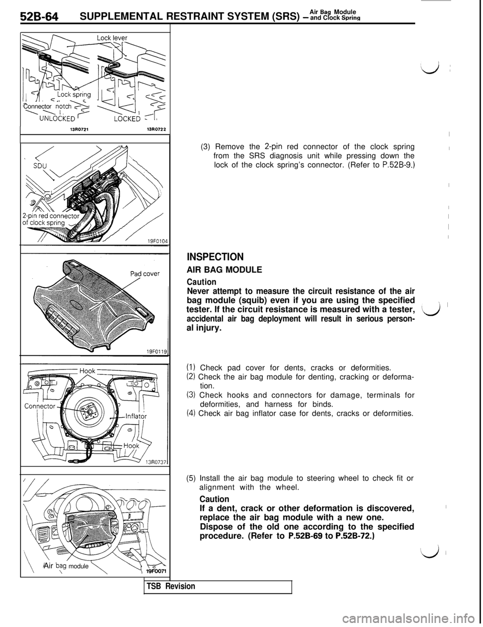
2-pin red connector of the clock spring
from the SRS diagnosis unit while pressing down the
lock of the clock spring’s connector. (Refer to
P.52B-9.)
INSPECTIONAIR BAG MODULE
Caution
Never attempt to measure the circuit resistance of the airbag module (squib) even if you are using the specified
tester. If the circuit resistance is measured with a tester,
accidental air bag deployment will result in serious person-al injury.
(1) Check pad cover for dents, cracks or deformities.
(2) Check the air bag module for denting, cracking or deforma-
tion.
(3) Check hooks and connectors for damage, terminals for
deformities, and harness for binds.
(4) Check air bag inflator case for dents, cracks or deformities.
TSB Revision(5) Install the air bag module to steering wheel to check fit or
alignment with the wheel.
CautionIf a dent, crack or other deformation is discovered,
replace the air bag module with a new one.
Dispose of the old one according to the specified
procedure. (Refer to
P52B-69 to P.52B-72.)
I
I
I
I
I
I
I
’ I
‘Lj
I
‘iJ i
Page 1075 of 1146
Air Bag ModuleSUPPLEMENTAL RESTRAINT SYSTEM (SRS) - and Clock Spring52B-65To SRS diagnosis unit
19FO101
i
LJLJ19FOlOSCLOCK SPRING
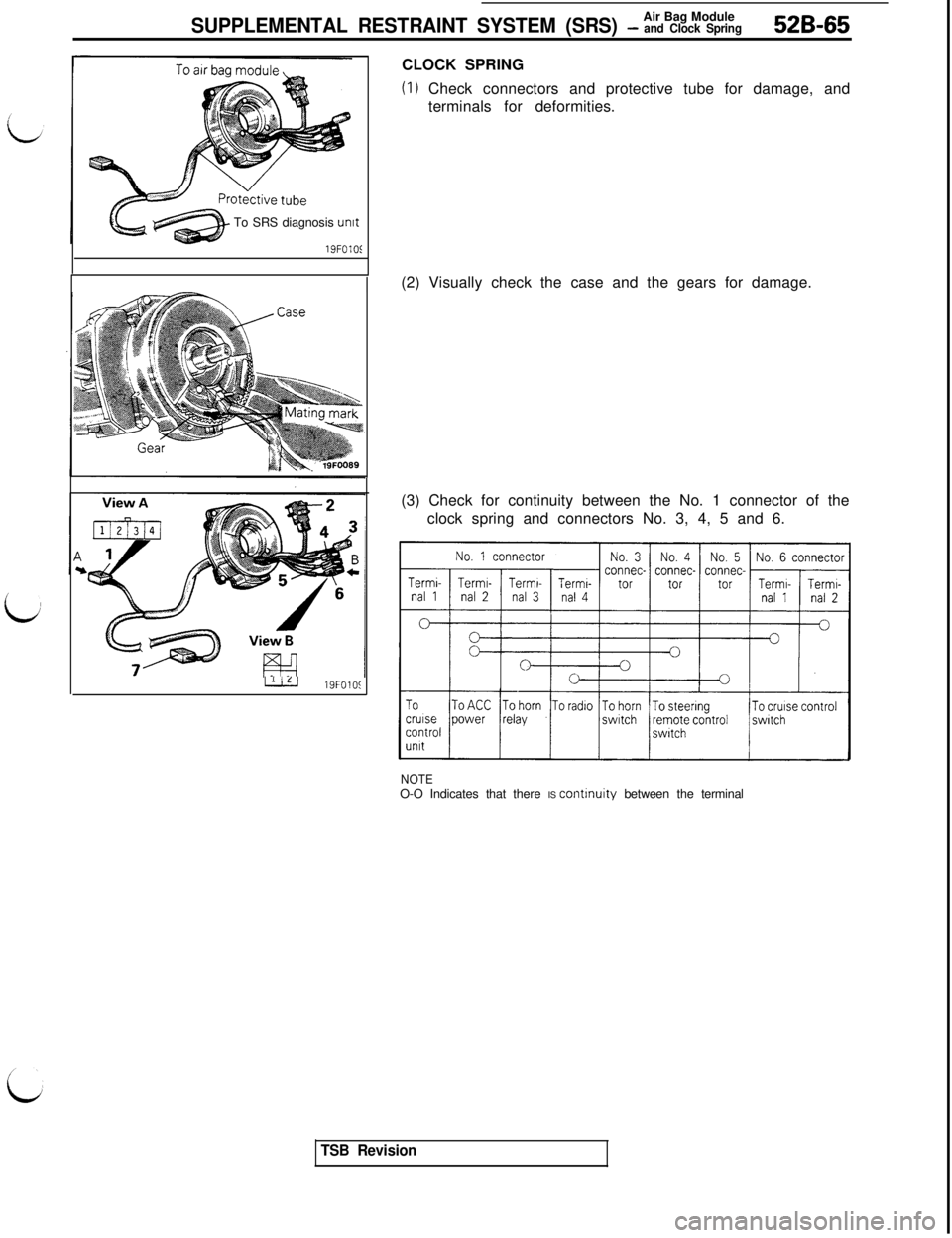
(I) Check connectors and protective tube for damage, and
terminals for deformities.
(2) Visually check the case and the gears for damage.
(3) Check for continuity between the No. 1 connector of the
clock spring and connectors No. 3, 4, 5 and 6.
NOTEO-O Indicates that there IS continuity between the terminal
TSB Revision
Page 1076 of 1146
52B-66Air Bag ModuleSUPPLEMENTAL RESTRAINT SYSTEM (SRS) - and Clock SpringMB991349
SRS CHeck Harness
No.7 connectcNo. 2 connector
View A
SRS Check Harness connector
16R219C
19FOlO!I
TSB Revision
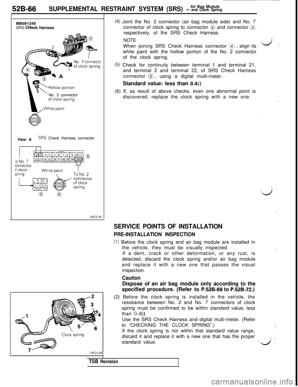
(4) Joint the No. 2 connector (air bag module side) and No. 7
connector of clock spring to connector @ and connector
@,respectively, of the SRS Check Harness.
NOTEWhen joining SRS Check Harness connector
(4) , align its
white paint with the hollow portion of the No. 2 connector
of the clock spring.
(5) Check for continuity between terminal 1 and terminal 21,
and terminal 2 and terminal 22, of SRS Check Harness
connector @ ,
using a digital multi-meter.
Standard value: less than
0.452(6) If, as result of above checks, even one abnormal point is
discovered, replace the clock spring with a new one.
SERVICE POINTS OF INSTALLATION
PRE-INSTALLATION INSPECTION
(I) Before the clock spring and air bag module are installed in
the vehicle, they must be visually inspected.
If a dent, crack or other deformation, or any rust, is
detected, discard the clock spring and/or air bag module
and replace it with a new one that passes the visual
inspection.
CautionDispose of an air bag module only according to the
specified procedure. (Refer to
P.52B-69 to P.52B-72.)(2) Before the clock spring is installed in the vehicle, the
resistance between No. 2 and No. 7 connectors of clock
spring must be confirmed to be within standard value; less
than
0.4(2.Use the SRS Check Harness and digital multi-meter. (Refer
to “CHECKING THE CLOCK SPRING”.)
If the clock spring is not within that standard value range,
discard it and replace it with a new one that has the proper
standard value.
d:
I
\
‘d :
I
I
I
LA
Page 1077 of 1146
Air Bag Module
SUPPLEMENTAL RESTRAINT SYSTEM (SRS) - and Clock Spring52B-67Multi-use Testkr
ROM pack
(MB991 341)(MB991 359)
Diagnosis/
service
data
oumutGround
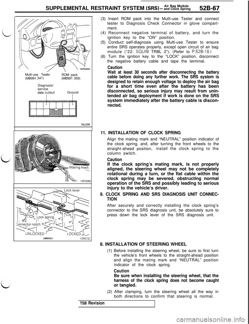
16LOO9'(3) Insert ROM pack into the Multi-use Tester and connect
tester to Diagnosis Check Connector in glove compart-
ment.
(4) Reconnect negative terminal of battery, and turn the
ignition key to the “ON” position.
(5) Conduct self-diagnosis using Multi-use Tester to ensure
entire SRS operates properly, except open circuit of air bag
module (“22. SQUIB TRBL 2”). (Refer to
P.52B-18.)(6) Turn the ignition key to the “LOCK” position, disconnect
the negative battery cable and tape the terminal.
Caution
Wait at least 30 seconds after disconnecting the battery
cable before doing any further work. The SRS system is
designed to retain enough voltage to deploy the air bagfor a short time even after the battery has been
disconnected, so serious injury may result from unin-
tended air bag deployment if work is done on the SRSsystem immediately after the battery cable is discon-
nected.
11. INSTALLATION OF CLOCK SPRINGAlign the mating mark and “NEUTRAL” position indicator of
the clock spring, and, after turning the front wheels to the
straight-ahead position,install the clock spring to the
column switch.
CautionIf the clock spring’s mating mark, is not properly
aligned, the steering wheel may not be completely
rotational during a turn, or the flat cable within the
clock spring may be severed, obstructing normal
operation of the SRS and possibly leading to serious
injury to the vehicle’s driver.
9. CLOCK SPRING AND SRS DIAGNOSIS UNIT CONNEC-
TIONAfter securely and correctly installing the clock spring’s
connector to the SRS diagnosis unit, be absolutely sure to
press down the lock lever of the SRS diagnosis unit.
13R072113R072;8. INSTALLATION OF STEERING WHEEL
(1) Before installing the steering wheel, be sure to first turn
the vehicle’s front wheels to the straight-ahead position
and align the mating mark and “NEUTRAL” position
indicator of the clock spring.
Caution
Be sure when installing the steering wheel, that the
harness of the clock spring does not become caughtor tangled.
(2) After clamping, turn the steering wheel all the way in
both directions to confirm that steering is normal.
TSB Revision
Page 1078 of 1146
52B-68SUPPLEMENTAL RESTRAINT SYSTEM (SRS) - %%%$kgSRS warning
light
/------ r--l
I
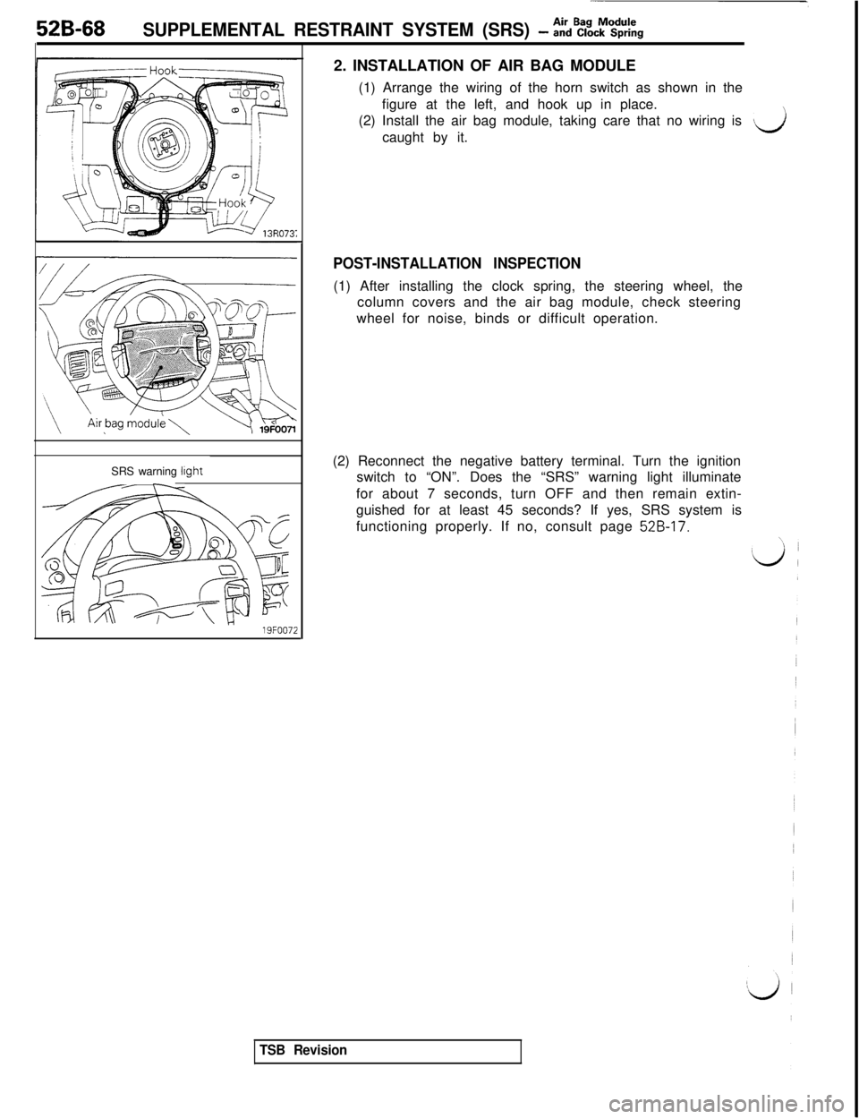
19FOO722. INSTALLATION OF AIR BAG MODULE
(1) Arrange the wiring of the horn switch as shown in the
figure at the left, and hook up in place.
(2) Install the air bag module, taking care that no wiring is
vicaught by it.
POST-INSTALLATION INSPECTION(1) After installing the clock spring, the steering wheel, the
column covers and the air bag module, check steering
wheel for noise, binds or difficult operation.
(2) Reconnect the negative battery terminal. Turn the ignition
switch to “ON”. Does the “SRS” warning light illuminate
for about 7 seconds, turn OFF and then remain extin-
guished for at least 45 seconds? If yes, SRS system is
functioning properly. If no, consult page
52B-17.
TSB Revision
Page 1080 of 1146
52B-70Air Bag ModuleSUPPLEMENTAL RESTRAINT SYSTEM (SRS) - Disposal Procedures
13R072113R0722
I
lnsulatlon
Clock\spring
connector
s+- MB68656019FOO88(3) Remove the rear console assembly. (Refer to GROUP
52A
- Floor Console.)
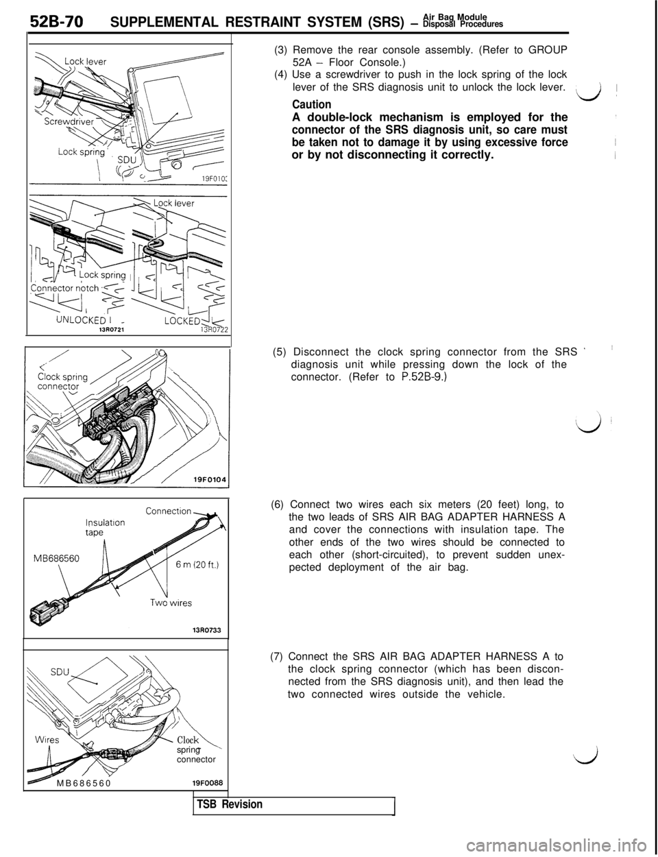
(4) Use a screwdriver to push in the lock spring of the lock
lever of the SRS diagnosis unit to unlock the lock lever.
Caution
L/! )A double-lock mechanism is employed for the
connector of the SRS diagnosis unit, so care must
be taken not to damage it by using excessive forceor by not disconnecting it correctly.
(5) Disconnect the clock spring connector from the SRS
’diagnosis unit while pressing down the lock of the
connector. (Refer to
P.52B-9.)(6) Connect two wires each six meters (20 feet) long, to
the two leads of SRS AIR BAG ADAPTER HARNESS A
and cover the connections with insulation tape. The
other ends of the two wires should be connected to
each other (short-circuited), to prevent sudden unex-
pected deployment of the air bag.
(7) Connect the SRS AIR BAG ADAPTER HARNESS A to
the clock spring connector (which has been discon-
nected from the SRS diagnosis unit), and then lead the
two connected wires outside the vehicle.
‘d
TSB Revision
Page 1083 of 1146
55-1
HEATER, AIR
CONDITIONER
AND VENTILATION
CONTENTSM55AA- -
HEATERS AND AIR CONDITIONING................3HEATER UNIT*........................................................................22
SPECIFICATIONS
....................................................................3REFRIGERANT LINE................................................................35General Specifications
........................................................3RESISTOR................................................................................20Lubricants
............................................................................4SAFETY PRECAUTIONS........................................................9Sealant and Adhesive............................................................4
Service Specifications3SERVICE ADJUSTMENT PROCEDURES............................10........................................................
SPECIAL TOOLS4Charging Procedures............................................................11
i
........................................................................Charging the Refrigerant....................................................12Compressor Drive Belt Adjustment....................................11
HEATERS AND MANUAL AIR CONDITIONER5Compressor Noise................................................................16
................................................16
AIR CONDITIONER SWITCH................................................21Handling Tubing andFittings
Idle-up Operation Check....................................................17
BELT LOCK CONTROLLER20Performance Test................................................................15....................................................
BLOWER ASSEMBLYPower Relay Check............................................................17............................................................23Refrigerant Leak Repair Procedure....................................15COMPRESSOR........................................................................
27TestProcedures....................................................................10
CONDENSER AND CONDENSER FAN MOTOR................33TROUBLESHOOTING............................................................5
ENGINE COOLANT TEMPERATURE SWITCH....................
39VENTILATORS (AIR INLET AND AIR OUTLET)................38
EVAPORATOR
........................................................................
25VENTILATORS (INSTRUMENT PANEL)*............................36
HEATER CONTROL ASSEMBLY*
........................................18CONTINUED ON NEXT PAGE
SUPPLEMENTAL RESTRAINT SYSTEM (SRS)
(1)A Supplemental Restraint System (SRS), which uses a driver-side air bag, has been installed in the 3000GT.(2)The SRS includes the following components: impact sensors, SRS diagnosis unit: SRS warning light, air bagmodule, clock spring, interconnecting wiring. Other SRS-related components (that may have to be
removed/installed in connection with SRS service or maintenance) are indicated in the table of contents byan asterisk (*).
WARNING!(1)Improper service or maintenance of any component of the SRS, or any SRS-related component, can lead to
personal injury or death to service personnel (from inadvertent firing of the air bag) or to the driver (fromrendering the
SRS inoperative).(2) Service or maintenance of any SRS component or SRS-related component must be performed only at anauthorized MITSUBISHI dealer.
(3) MITSUBISHI dealer personnel must thoroughly review this manual, and especially its GROUP 52B
-Supplemental Restraint System (SRS), before beginning any service or maintenance of any component of theSRS or any SRS-related component.
Page 1084 of 1146

55-2FULL AUTO AIR CONDITIONER........................40OTHER PARTS........................................................................62
AIR-CONDITIONER CONTROL PANEL*,POWER TRANSISTOR, BELT LOCK CONTROLLER........57
AIR-CONDITIONER CONTROL UNIT*................................56
REFRIGERANT LINE................................................................62
COMPRESSOR
........................................................................62SAFETY PRECAUTlONS........................................................56
CONDENSER AND CONDENSER FAN MOTOR
................
62SENSORS....................................................................................60
DAMPER CONTROL MOTOR ASSEMBLY*........................
58SERVICE ADJUSTMENT PROCEDURES............................56
ENGINE COOLANT TEMPERATURE SWITCH
....................62
TROUBLESHOOTING............................................................40