Page 1119 of 1146
HEATERS AND MANUAL AIR CONDITIONER -Ventilators (Instrument Panel) 55-37
/ 2OFOO321
SERVICE POINTS OF REMOVALM55YBAH
15. REMOVAL OF DEFROSTER GARNISHES
Using the trim stick, remove the defroster garnishes fromthe instrument panel.
16. REMOVAL OF PHOTO SENSORUsing the trim stick, remove the photo sensor from the
defroster garnish.
17. REMOVAL OF CENTER AIR OUTLET ASSEMBLY
Disengaging the clips (2 positions) of the center air-outlet
assembly with a flat tip screwdriver, remove the center airoutlet assembly with the trim stick.
1 TSB Revision
Page 1123 of 1146

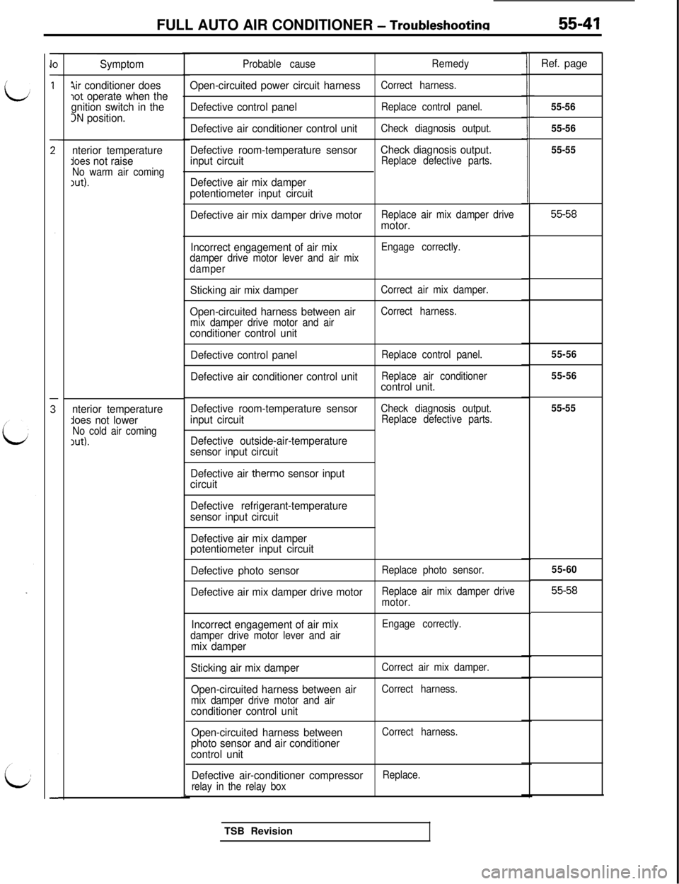
FULL AUTO AIR CONDITIONER - Troubleshootina55-41
Symptom
4ir conditioner doeslot operate when the
gnition switch in the
3N position.
nterior temperature
lees not raiseNo warm air coming1ut).
nterior temperatureAoes not lowerNo cold air coming,ut).Probable cause
Open-circuited power circuit harness
Defective control panel
Defective air conditioner control unit
Defective room-temperature sensor
input circuit
Defective air mix damper
potentiometer input circuit
Remedy
Correct harness.
Replace control panel.
Check diagnosis output.
Check diagnosis output.Replace defective parts.
Defective air mix damper drive motorReplace air mix damper drivemotor.
Incorrect engagement of air mix
damper drive motor lever and air mix
damperEngage correctly.
Sticking air mix damper
Open-circuited harness between air
mix damper drive motor and airconditioner control unit
Defective control panel
Defective air conditioner control unit
Correct air mix damper.
Correct harness.
Replace control panel.
Replace air conditioner
control unit.
Defective room-temperature sensor
input circuit
Defective outside-air-temperature
sensor input circuit
Check diagnosis output.
Replace defective parts.
Defective air therm0 sensor input
circuit
Defective refrigerant-temperature
sensor input circuit
Defective air mix damper
potentiometer input circuit
Defective photo sensor
Replace photo sensor.
Defective air mix damper drive motorReplace air mix damper drive
motor.
Incorrect engagement of air mixdamper drive motor lever and airmix damper
Engage correctly.
Sticking air mix damper
Open-circuited harness between air
mix damper drive motor and airconditioner control unit
Open-circuited harness between
photo sensor and air conditioner
control unit
Correct air mix damper.
Correct harness.
Correct harness.
Defective air-conditioner compressorReplace.
relay in the relay boxTSB Revision
Ref. page
55-56
55-56
55-55
55-58
55-56
55-56
55-55
55-60
55-58
Page 1126 of 1146

55-44FULL AUTO AIR CONDITIONER - Troubleshooting
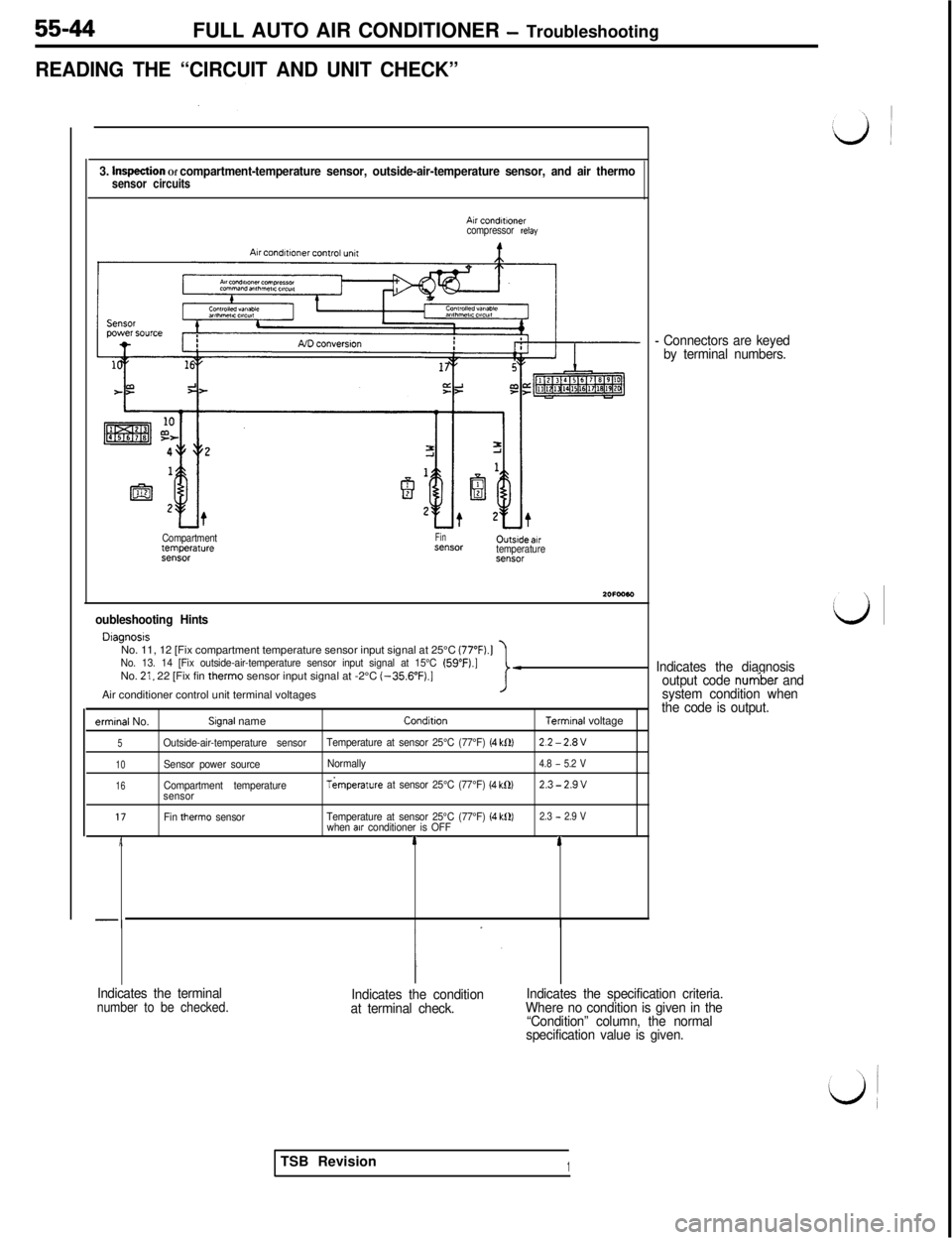
READING THE “CIRCUIT AND UNIT CHECK”
3. hvqection Of compartment-temperature sensor, outside-air-temperature sensor, and air thermosensor circuits
Air condMnercompressor relay
Compartmenttemperat”re93”SCNFinX”SCH0utsrde.wtemperatureX”SOl
oubleshooting Hints
DlagnosrsNo. 11, 12 [Fix compartment temperature sensor input signal at 25°C (77”F).]
No. 13. 14 [Fix outside-air-temperature sensor input signal at 15°C (59”F).]No. 21, 22 [Fix fin therm0 sensor input signal at -2°C (-356”F).]Air conditioner control unit terminal voltagesI-
ermrnal No.Slgnal nameConditronTerrmnal voltage
5Outside-air-temperature sensorTemperature at sensor 25°C (77°F) (4 kf2)2.2-2.8V
10Sensor power sourceNormally4.8 - 5.2 V
16Compartment temperatureTkmperature at sensor 25°C (77°F) (4 k0)2.3-2.9vsensor
17Fin therm0 sensorTemperature at sensor 25°C (77°F) (4 k0)2.3 - 2.9 Vwhen alr conditioner is OFFA14
-
- Connectors are keyed
by terminal numbers.
Indicates the diagnosis
output code
nur6be.r and
system condition when
the code is output.
Indicates the terminal
number to be checked.Indicates the condition
at terminal check.Indicates the specification criteria.
Where no condition is given in the
“Condition” column, the normal
specification value is given.TSB Revision
1
Page 1128 of 1146
55-46FULL AUTO AIR CONDITIONER - Troubleshooting
2. Inspection of potentiometer circuit
Outlet selector
command c~rcutl
i IComparator&8.
c!
t
Ia
Y[ND conversionA/D conversvmWC”l,CllCUll\/ \,1.y
lo” 6”Air conditioner control unit7‘”
94 72-2t4 3
~1
Air mix damper
potentiometer
z=-
4;t
e11I
Outlet
selector
damper
potentiometer
2OFOO57Troubleshooting Hints
l Diagnosis
No. 31 (Fix air mix damper at MAX. HOT position, or at MAX. COOL position when it is at MAX. COOL
position.)
No. 32 (Fix outlet selector damper at FACE position, or at FACE pgsition when it is at FACE position.)l Air conditioner control unit terminal voltages
Sensor power sourceNormally4.8 - 5.2 V
TSB Revision
Page 1129 of 1146

FULL AUTO AIR CONDITIONER - Troubleshootinn55-47
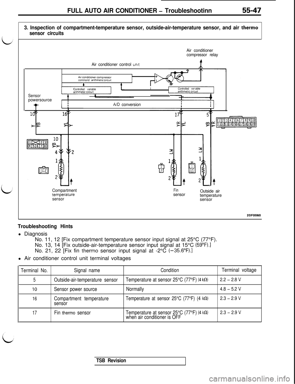
3. Inspection of compartment-temperature sensor, outside-air-temperature sensor, and air therm0
sensor circuits
Air conditioner
compressor relay
Air conditioner control
unitA~rconditlonercompiessor
command arllhmew ctrcutc#
Sensorpowersource
Controlled variableIControlled variable
-IIIA/D conversion
Compartment
temperaruresensor
Finsensor
?J
Outside air
temperature
sensor2OFOO60
Troubleshooting Hintsl Diagnosis
No. 11, 12 [Fix compartment temperature sensor input signal at 25°C (77°F).
No. 13, 14 [Fix outside-air-temperature sensor input signal at 15°C
(59”Fj.INo. 21, 22 [Fix fin
therm0 sensor input signal at -2°C (-35.6”FJ.ll Air conditioner control unit terminal voltages
Terminal No.Signal nameConditionTerminal voltage
5Outside-air-temperature sensorTemperature at sensor 25°C (77°F) (4 klR)2.2 - 2.8 V
10Sensor power sourceNormally4.8 - 5.2 V
16Compartment temperatureTemperature at sensor 25°C (77°F) (4 klR)2.3 - 2.9 V
sensor
17Fin therm0 sensorTemperature at sensor 25°C (77°F) (4 k0)2.3 - 2.9 Vwhen air conditioner is OFF
TSB Revision
Page 1130 of 1146
55-48FULL AUTO AIR CONDITIONER - Troubleshooting
[4. Inspection of water-temperature sensor and photo sensor circuits (
Air conditionercontrol panel
A
{ f*)- Potentiometer
‘>/b Damper drive
motor
\/\,9 Air conditioner
a 7 control unit
Water
temperature
sensor
m
Air conditionerEach sensorcontrol unit&
Air control panel
I.L .Solar radmtmnFin speed arlth-compensating ClrC”itmetIC ClrCUlt#t
A/D convertionND convemon
J2010043
I-
Troubleshooting Hintsl Air conditioner control unit terminal voltages
Terminal No.Signal nameConditionTerminal voltage
19Photo sensor 0llluminance 100,000 lux or more-0.1 to -0.2 v
llluminance less than 0 Iuxov
20Photo sensor 0Normallyov
9Water-temperature sensor 0Switch OFF [Engine coolant temperature
less than 50°C (122”F)]
Battery voltage
Switch ON [Engine coolant temperature
0 V
50°C (122°F) or higher]
1 TSB Revision
Page 1131 of 1146
FULL AUTO AIR CONDITIONER - Troubleshooting55-495. Inspection of belt lock controller circuit
Compressor relay
tAir conditioner control unitAir conditioner
+control panelAir
condltloner,c.compressor commandAH condmonerarithmetic
circuitcompressor ONstgnal
ComparatorAir condltlonercompressor ON signal20 FOO58
Revolution pickup sensor
LiTroubleshooting Hintsl Air conditioner control unit terminal voltages
Terminal No.
Signal nameConditionTerminal voltage
11Air conditioner outputCompressor ONIO V to battery voltage
TSB Revision
Page 1136 of 1146

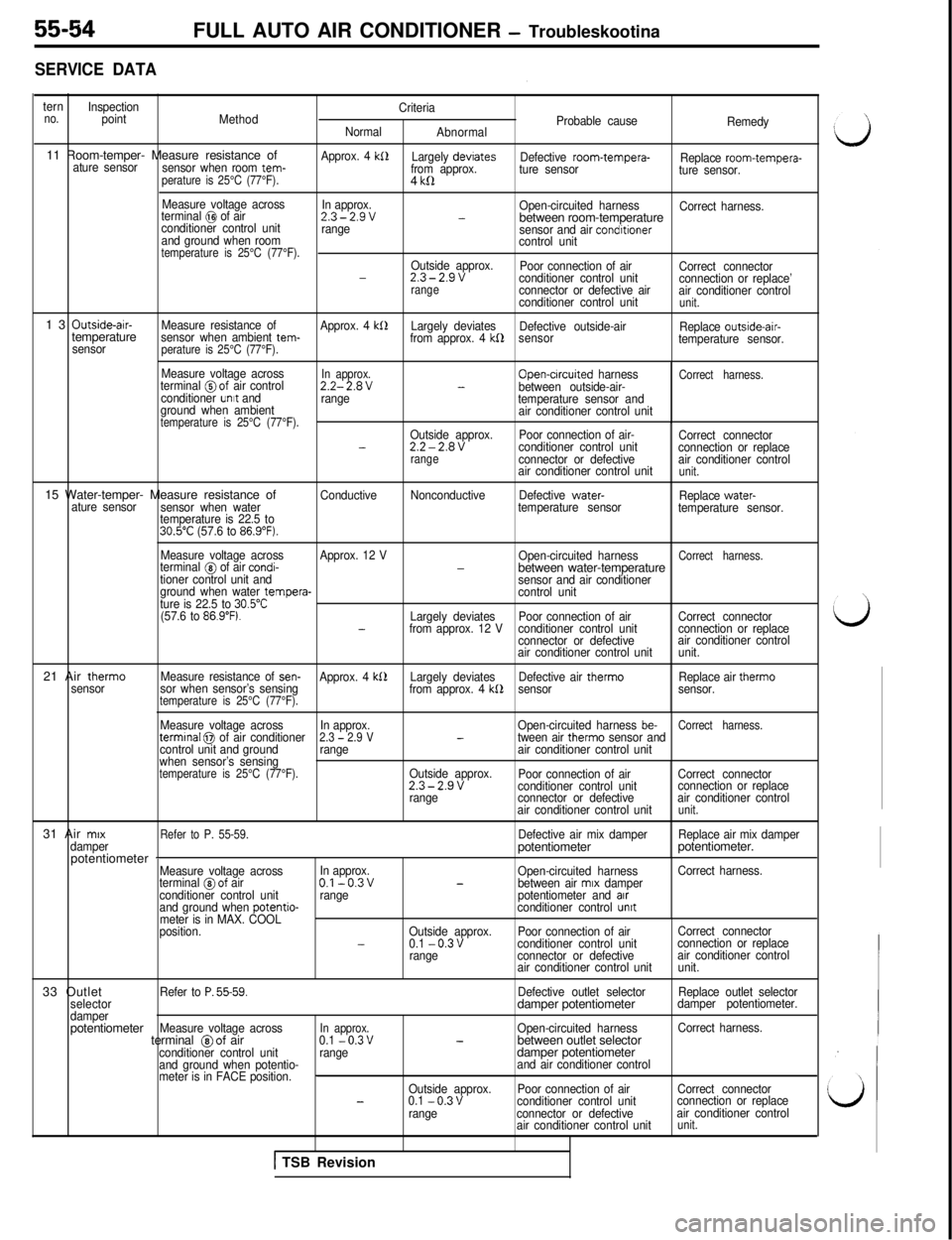
SERVICE DATA
ternno.Inspection
point
MethodCriteria
Probable cause
Normal
AbnormalRemedy11 Room-temper- Measure resistance of
sensor when room tem- ature sensorperature is 25°C (77°F).
Approx. 4 kS1Largely devrates
from approx.Defective room-tempera-
Replace room-tempera-
ture sensor
ture sensor.4
kll
Measure voltage across
In approx.
terminal @I of airOpen-circuited harness
Correct harness.2.3-2.9v-conditioner control unitbetween room-temperaturerange
sensor and air condrtionerand ground when room
control unittemperature is 25°C (77°F).Outside approx.
Poor connection of air
Correct connector-2.3-2.9vconditioner control unit
connection or replace’rangeconnector or defective air
air conditioner control
conditioner control unitunit.13
Outside-air-
Measure resistance of
Approx. 4 kllLargely deviates
Defective outside-air
Replace outside-air-temperaturesensor when ambient tem-
from approx. 4 kf2sensor
temperature sensor.
sensorperature is 25°C (77°F).
Measure voltage acrossIn approx.terminal @of air controlOpen-crrcuited harnessCorrect harness.2.2-2.8V-between outside-air-
conditioner unrt and
range
temperature sensor and
ground when ambient
air conditioner control unit
temperature is 25°C (77°F).Outside approx.Poor connection of air-
Correct connector-2.2-2.8Vconditioner control unit
connection or replacerangeconnector or defectiveair conditioner control
air conditioner control unitunit.15 Water-temper- Measure resistance of
ConductiveNonconductiveDefective water-
Replace water-
ature sensor
sensor when watertemperature sensor
temperature sensor.
temperature is 22.5 to
30.5”C (57.6 to 86.9”F).21 Air therm0
sensorMeasure voltage acrossApprox. 12 V
Open-circuited harness
Correct harness.terminal @ of air condi--between water-temperaturetioner control unit and
sensor and air conditioner
ground when water tempera-
control unit
ture is 22.5 to 30.5”C(57.6 to 86.9”F).Largely deviatesPoor connection of airCorrect connector-from approx. 12 Vconditioner control unitconnection or replace
connector or defectiveair conditioner control
air conditioner control unitunit.
Measure resistance of
sen-Approx. 4 kS2Largely deviatesDefective air therm0Replace air therm0
sor when sensor’s sensing
from approx. 4 kb2sensorsensor.temperature is 25°C (77°F).
Measure voltage acrossIn approx.Open-circuited harness be-Correct harness.termrnal 0 of air conditioner2.3 - 2.9 V-tween air therm0 sensor and
control unit and groundrangeair conditioner control unit
when sensor’s sensing
temperature is 25°C (77°F).Outside approx.
Poor connection of airCorrect connector2.3-2.9vconditioner control unitconnection or replace
rangeconnector or defectiveair conditioner control
air conditioner control unit
unit.31 Air
mrx
Refer to P. 55-59.Defective air mix damperReplace air mix damper
damperpotentiometerpotentiometer.
potentiometer
-Measure voltage acrossIn approx.
Open-circuited harnessCorrect harness.
terminal @of airO.l-0.3v-between air mrx damper
conditioner control unitrangepotentiometer and arrand ground when potentio-conditioner control unrtmeter is in MAX. COOL
position.Outside approx.Poor connection of airCorrect connector
-0.1 -0.3vconditioner control unitconnection or replace
rangeconnector or defectiveair conditioner control
air conditioner control unitunit.33 Outlet
Refer to P. 55-59.Defective outlet selectorReplace outlet selector
selectordamper potentiometerdamper potentiometer.
damperpotentiometer
Measure voltage acrossIn approx.Open-circuited harnessCorrect harness.terminal @of air0.1 -0.3v-between outlet selectorconditioner control unitrangedamper potentiometerand ground when potentio-and air conditioner control
meter is in FACE position._Outside approx.Poor connection of airCorrect connector-0.1 -0.3vconditioner control unitconnection or replace
rangeconnector or defectiveair conditioner control
air conditioner control unit
unit.FULL AUTO AIR CONDITIONER
- Troubleskootina
1 TSB Revision