Page 1089 of 1146

L
2OFOO85HEATERS AND MANUAL AIR CONDITIONER
- Trqubleshooting55-7
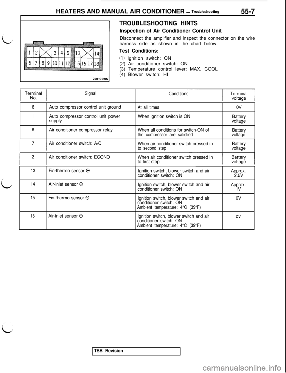
TROUBLESHOOTING HINTSInspection of Air Conditioner Control Unit
Disconnect the amplifier and inspect the connector on the wire
harness side as shown in the chart below.
Test Conditions:
(1) Ignition switch: ON
(2) Air conditioner switch: ON
(3) Temperature control lever: MAX. COOL
(4) Blower switch: HI
1 Terrrnal 1Signal
Conditions
8Auto compressor control unit groundAt all timesov
1Auto compressor control unit power
SUPPlY
When ignition switch is ON
Battery
voltage
6Air conditioner compressor relay
When all conditions for switch-ON of
Battery
the compressor are satisfiedvoltage
I ’I
Air conditioner switch: A/C
When air conditioner switch pressed inBattery
to second stepvoltage
Air conditioner switch: ECONO
When air conditioner switch pressed in
to first step
13Fin-therm0 sensor 0Ignition switch, blower switch and airApprox.
conditioner switch: ON2.5V/
LJ14Air-inlet sensor 0Ignition switch, blower switch and air
conditioner switch: ONApprox.IV
15Fin-therm0 sensor 0Ignition switch, blower switch and air
conditioner switch: ON
Ambient temperature: 4°C (39°F)
OV
18Air-inlet sensor 0Ignition switch, blower switch and air
conditioner switch: ON
Ambient temperature: 4°C (39°F)ov
TSB Revision
Page 1090 of 1146

55-8HEATERS AND MANUAL AIR CONDITIONER - Troubleshooting
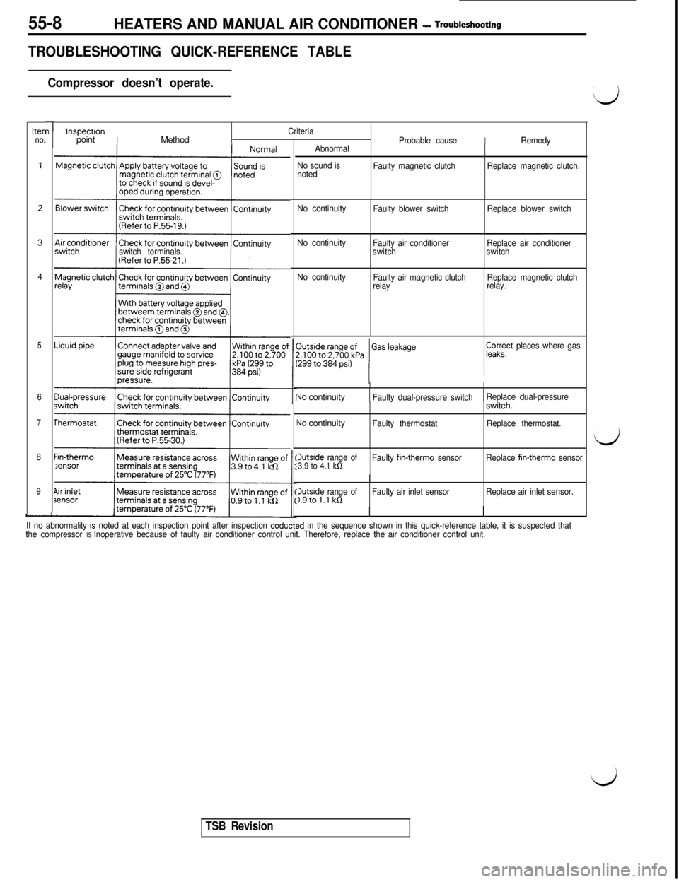
TROUBLESHOOTING QUICK-REFERENCE TABLE
Compressor doesn’t operate.
hen
no.
4
5
6
7
8
9
-
I
I
/
L
switch terminals.
Sensor
”
1
InspectronCriteriapointIMethodProbable causeIRemedy
Abnormal
No sound is
notedFaulty magnetic clutchReplace magnetic clutch.
No continuity
Faulty blower switchReplace blower switch
No continuity
Faulty air conditioner
switchReplace air conditioner
switch.
No continuity
Faulty air magnetic clutch
relayReplace magnetic clutch
relay.
pa;?’ places where gas
II
Vo continuityFaulty dual-pressure switchReplace dual-pressure
\Jo continuityIFaulty thermostatswitch.Replace thermostat.
Outside range of3.9 to 4.1 kfiFaulty fin-therm0 sensorReplace fin-therm0 sensor
3utside range ofFaulty air inlet sensor1.9tol.l kQReplace air inlet sensor.
If no abnormality
is noted at each inspection point after inspection coducted in the sequence shown in this quick-reference table, it is suspected that
the compressor IS Inoperative because of faulty air conditioner control unit. Therefore, replace the air conditioner control unit.
d
d
TSB Revision
Page 1093 of 1146

HEATERS AND MANUAL AIR CONDITIONER -Service Adjustment Procedures 55 1 1
lr In et sensor
2oFoo57
UC03xD:c.-;am$2lYXSC0x.x
xa0:: :,:::25 cc,ii 77h>Temperature20A043F
argqse
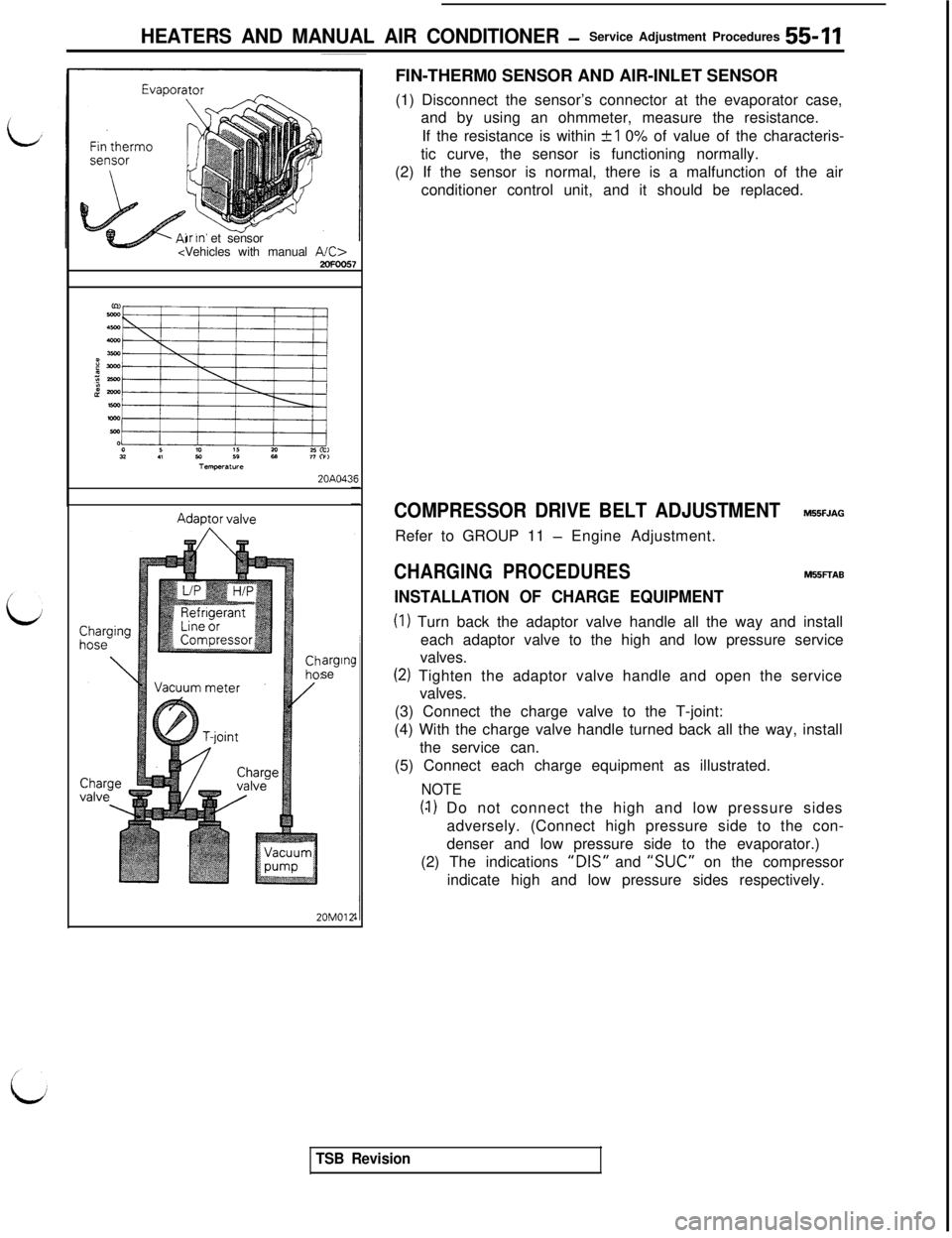
20M012FIN-THERM0 SENSOR AND AIR-INLET SENSOR
(1) Disconnect the sensor’s connector at the evaporator case,
and by using an ohmmeter, measure the resistance.
If the resistance is within
+I 0% of value of the characteris-
tic curve, the sensor is functioning normally.
(2) If the sensor is normal, there is a malfunction of the air
conditioner control unit, and it should be replaced.
COMPRESSOR DRIVE BELT ADJUSTMENTM55FJAGRefer to GROUP 11
- Engine Adjustment.
CHARGING PROCEDURESM55FTAB
INSTALLATION OF CHARGE EQUIPMENT
(I) Turn back the adaptor valve handle all the way and install
each adaptor valve to the high and low pressure service
valves.
(2) Tighten the adaptor valve handle and open the service
valves.
(3) Connect the charge valve to the T-joint:
(4) With the charge valve handle turned back all the way, install
the service can.
(5) Connect each charge equipment as illustrated.
NOTE
(4) Do not connect the high and low pressure sides
adversely. (Connect high pressure side to the con-
denser and low pressure side to the evaporator.)
(2) The indications
“DIS” and “SUC” on the compressor
indicate high and low pressure sides respectively.
TSB Revision
Page 1107 of 1146
HEATERS AND MANUAL AIR CONDITIONER - Evaporator55-25
EVAPORATOR
M55RA- -
/REMOVAL AND INSTALLATION
9.0- 11 Nm
7.0 - 8.0 ftlbs.
i
O-ringRemoval steps
l *I, Connection of liquid pipe and suction hose
2. O-ring
3. Drain hose
4. Stopper
5. Glove box
6. Glove box outer case assembly
7. Under cover
8. Lower frame
9. A/C control unit
10. Evaporator
Pre-removal and Post-installation Operationl Discharge and Charging of Refrigerant
l Removal and lns~allation of Battery
SERVICE POINTS OF REMOVALM55RBAl
1.DISCONNECTION OF LIQUID PIPE AND SUCTION HOSEIf the hoses or pipes are disconnected, cap the hoses or
pipes with a blank plug to prevent entry of dust, dirt, and
water.
INSPECTIONM55RcADl Check for damage of the evaporator fin part.
l Check for damage or collapse of the drain hose.
l Check for peeling or cracking of the insulator.
FIN-THERM0 SENSOR AND AIR-INLET SENSOR CHECK
For information concerning the checking procedures, refer to
P.55-11.
iTSB Revision
Page 1108 of 1146
55-26HEATERS AND MANUAL AIR CONDITIONER - Evaporator
DISASSEMBLY AND REASSEMBLYM55RE- -Compressor oil: Freol S-83 or
Suniso 5GS
Disassembly steps
4*1. Clips
2. Evaporater case (upper)3.
Fin therm0 sensor4. AirInlet sensor
4*
5. Evaporator case (lower)
6.Evaporator assembly
7.Grommet8.Insulator9.Rubber insulator10.Clip11. Expansion valve
10/
9
/2OFOO40
1TSB Revision
SERVICE POINTS OF DISASSEMBLYM55RFAJ1. REMOVAL OF CLIPS
Remove the clips with a screwdriver covered with a shoptowel to prevent damage to case surfaces.
11. REMOVAL OF EXPANSION VALVE
Loosen the flare nut by using two wrenches (for both theinlet and outlet).
Page 1111 of 1146
HEATERS AND MANUAL AIR CONDITIONER - Compressor
DISASSEMBLY AND REASSEMBLY
55-29
M55SE- -16
152OFOO97
Magnetic clutch disassembly steps
1. Bolts
2. Pulley
l * l *3. Nutl *4. Armature plate
gI i;yirring
l *7. Snap ringF* 8. Clutch coil9. ShimsControl valve disassembly
13. Snap ring14. Control valveThermostat and revolution pick up sensor disassem-
bly steps
15. Plate16. Thermostat and revolution pick up sensorHigh pressure relief valve disassembly steps
10. Cover11. Dust cover
12. High pressure relief valveTSB Revision
Page 1113 of 1146

HEATERS AND MANUAL AIR CONDITIONER - Compressor55-3120N003d
2OFOO96
I
Ec-3
3180?+I! (25)zz
h34\
*
Engine speed rpm2OPO2S
\CrankshaftTapered part
20A0157
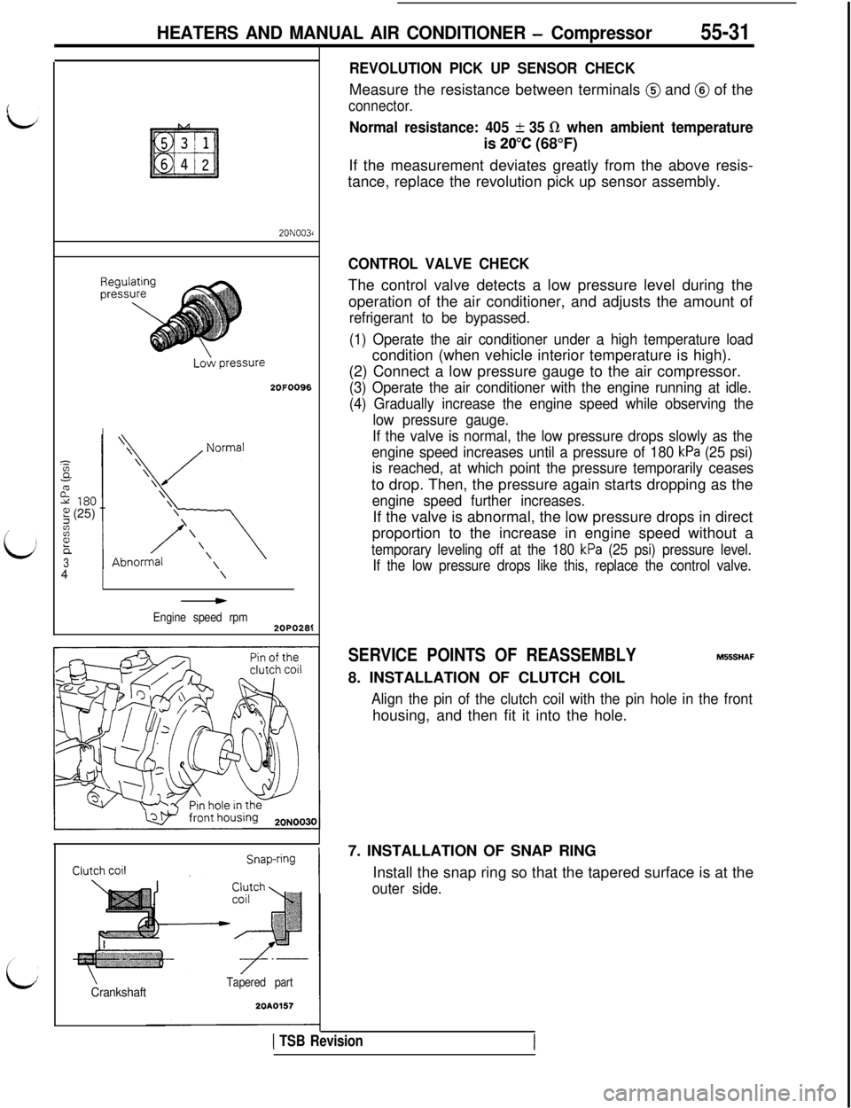
REVOLUTION PICK UP SENSOR CHECKMeasure the resistance between terminals
@ and @ of the
connector.
Normal resistance: 405 + 35 R when ambient temperatureis
20°C (68°F)
If the measurement deviates greatly from the above resis-
tance, replace the revolution pick up sensor assembly.
CONTROL VALVE CHECKThe control valve detects a low pressure level during the
operation of the air conditioner, and adjusts the amount of
refrigerant to be bypassed.
(1) Operate the air conditioner under a high temperature loadcondition (when vehicle interior temperature is high).
(2) Connect a low pressure gauge to the air compressor.
(3) Operate the air conditioner with the engine running at idle.
(4) Gradually increase the engine speed while observing the
low pressure gauge.
If the valve is normal, the low pressure drops slowly as the
engine speed increases until a pressure of 180
kPa (25 psi)
is reached, at which point the pressure temporarily ceasesto drop. Then, the pressure again starts dropping as the
engine speed further increases.If the valve is abnormal, the low pressure drops in direct
proportion to the increase in engine speed without a
temporary leveling off at the 180 kPa (25 psi) pressure level.
If the low pressure drops like this, replace the control valve.
SERVICE POINTS OF REASSEMBLYM556HAF
8. INSTALLATION OF CLUTCH COIL
Align the pin of the clutch coil with the pin hole in the fronthousing, and then fit it into the hole.
7. INSTALLATION OF SNAP RING
Install the snap ring so that the tapered surface is at the
outer side.
1 TSB Revision
Page 1118 of 1146
55-36 HEATERS AND MANUAL AIR CONDITIONER -Ventilators (Instrument Panel)
VENTILATORS (INSTRUMENT PANEL)M55YA- -
REMOVAL AND INSTALLATION
-16
/‘4
Removal steps
l * +a1. Knee protector
(Refer to GROUP 52A-Instrument Panel.)
2. Foot shower duct
3. Lap cooler duct
4. Under cover
5. Belt lock controller
6. Side defroster hoses A
7. Duct (Vehicles without air conditioner)
** l +8. instrument panel (Refer to GROUP 52A-instrument Panel.)
9. Center duct
10. Air duct (right side)
11. Air duct (left side)12. Distribution duct (center)
13.Defroster duct14. Side defroster hoses B
15. Defroster garnishes
16.Photo sensor17. Center air outlet assembly
18. Side air outlet assembly
19. Distribution duct (foot)2OFOO55
Ij
I
I
I
.I
I
I
!
I
‘d
TSB RevisionI