Page 2097 of 4087
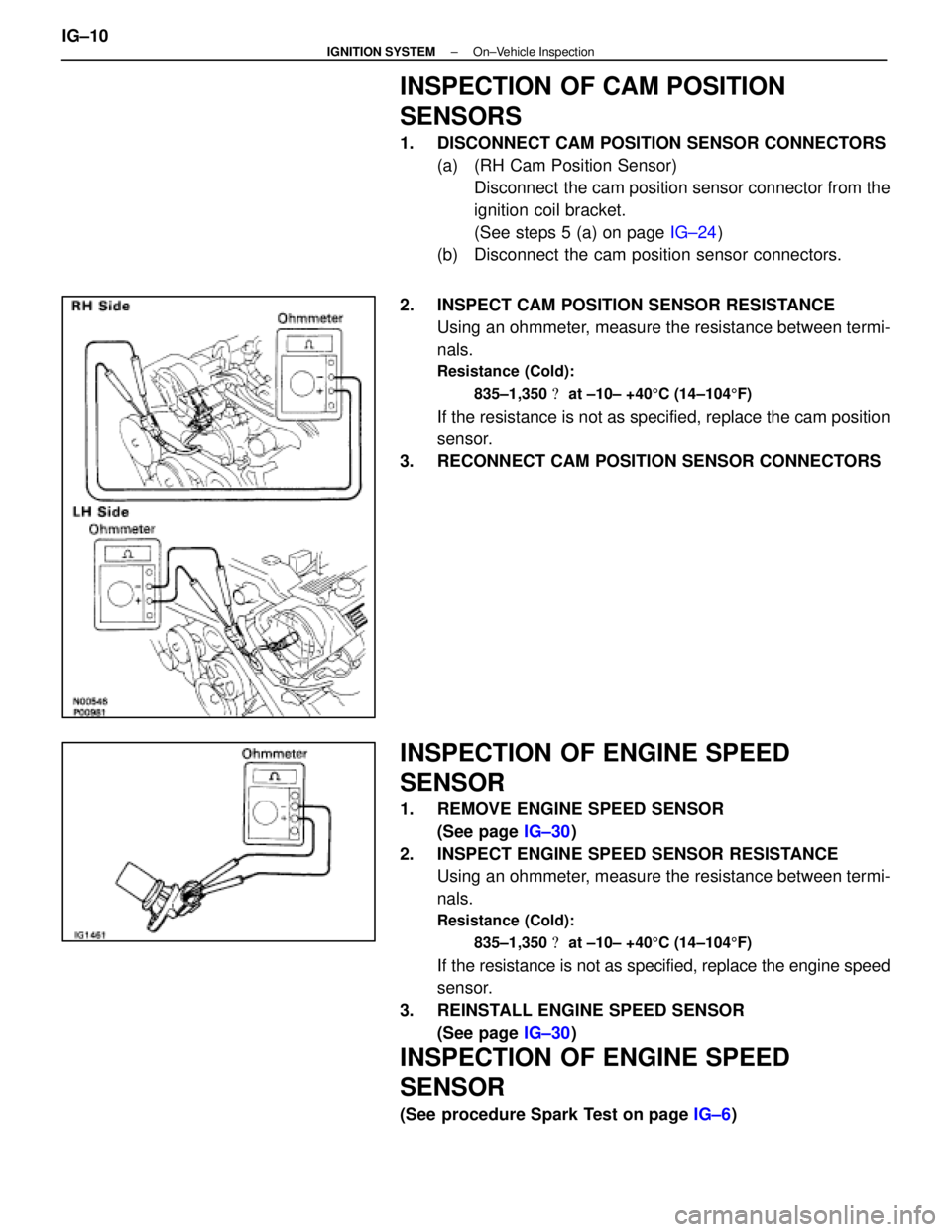
INSPECTION OF CAM POSITION
SENSORS
1. DISCONNECT CAM POSITION SENSOR CONNECTORS(a) (RH Cam Position Sensor)Disconnect the cam position sensor connector from the
ignition coil bracket.
(See steps 5 (a) on page IG±24)
(b) Disconnect the cam position sensor connectors.
2. INSPECT CAM POSITION SENSOR RESISTANCE Using an ohmmeter, measure the resistance between termi-
nals.
Resistance (Cold):
835±1,350 � at ±10± +40 5C (14±104 5F)
If the resistance is not as specified, replace the cam position
sensor.
3. RECONNECT CAM POSITION SENSOR CONNECTORS
INSPECTION OF ENGINE SPEED
SENSOR
1. REMOVE ENGINE SPEED SENSOR (See page IG±30)
2. INSPECT ENGINE SPEED SENSOR RESISTANCE Using an ohmmeter, measure the resistance between termi-
nals.
Resistance (Cold):
835±1,350 � at ±10± +40 5C (14±104 5F)
If the resistance is not as specified, replace the engine speed
sensor.
3. REINSTALL ENGINE SPEED SENSOR (See page IG±30)
INSPECTION OF ENGINE SPEED
SENSOR
(See procedure Spark Test on page IG±6)
IG±10
±
IGNITION SYSTEM On±Vehicle Inspection
WhereEverybodyKnowsYourName
Page 2099 of 4087
2. REMOVE INTAKE AIR CONNECTOR(a) Disconnect the following hoses:(1) Air hose from ISC valve
(2) Air hose (from PS air control valve) from intake air connector
(b) Remove the bolt holding the intake air connector to the cylinder head cover.
(c) Loosen the two hose clamps.
(d) Disconnect the intake air connector from the throttle
body and air cleaner hose, and remove the throttle body.
3. REMOVE UPPER HIGH±TENSION CORD COVER (a) Remove the two mounting bolts.
(b) Disconnect the front side claw groove of the cord coverfrom the claw of the lower cover, and remove the cord
cover.
4. REMOVE RH ENGINE WIRE COVER Remove the bolt and engine wire cover.
5. REMOVE LH ENGINE WIRE COVER Remove the two bolts and engine wire cover.
IG±12
±
IGNITION SYSTEM High±Tension Cords and Cord Clamps
WhereEverybodyKnowsYourName
Page 2105 of 4087
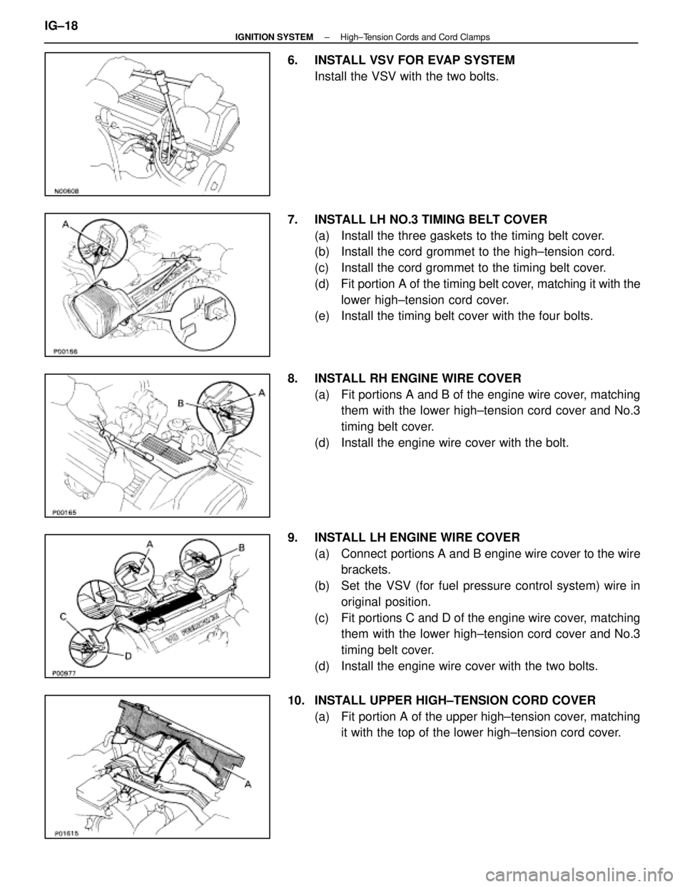
6. INSTALL VSV FOR EVAP SYSTEMInstall the VSV with the two bolts.
7. INSTALL LH NO.3 TIMING BELT COVER (a) Install the three gaskets to the timing belt cover.
(b) Install the cord grommet to the high±tension cord.
(c) Install the cord grommet to the timing belt cover.
(d) Fit portion A of the timing belt cover, matching it with the
lower high±tension cord cover.
(e) Install the timing belt cover with the four bolts.
8. INSTALL RH ENGINE WIRE COVER (a) Fit portions A and B of the engine wire cover, matchingthem with the lower high±tension cord cover and No.3
timing belt cover.
(d) Install the engine wire cover with the bolt.
9. INSTALL LH ENGINE WIRE COVER (a) Connect portions A and B engine wire cover to the wirebrackets.
(b) Set the VSV (for fuel pressure control system) wire in original position.
(c) Fit portions C and D of the engine wire cover, matching them with the lower high±tension cord cover and No.3
timing belt cover.
(d) Install the engine wire cover with the two bolts.
10. INSTALL UPPER HIGH±TENSION CORD COVER (a) Fit portion A of the upper high±tension cover, matchingit with the top of the lower high±tension cord cover.
IG±18
±
IGNITION SYSTEM High±Tension Cords and Cord Clamps
WhereEverybodyKnowsYourName
Page 2106 of 4087
(b) Push the front side of the high±tension cord cover, andconnect the front side claw groove of the upper
high±tension cord cover to the claw of the lower
high±tension cord cover.
(c) Install the upper high±tension cord cover with the two bolts.
11. INSTALL INTAKE AIR CONNECTOR (a) Connect the end portions of the intake air connector tothe throttle body and air cleaner hose.
(b) Tighten the two hose clamps.
(c) Install the bolt holding the intake air connector to the cylinder head cover.
(d) Connect the following hoses: (1) Air hose to ISC valve
(2) Air hose (from PS air control valve) to intake air con-
nector
12. CONNECT CABLE TO NEGATIVE TERMINAL OF BATTERY
13. CHECK THAT ENGINE STARTS
±
IGNITION SYSTEM High±Tension Cords and Cord ClampsIG±19
WhereEverybodyKnowsYourName
Page 2109 of 4087
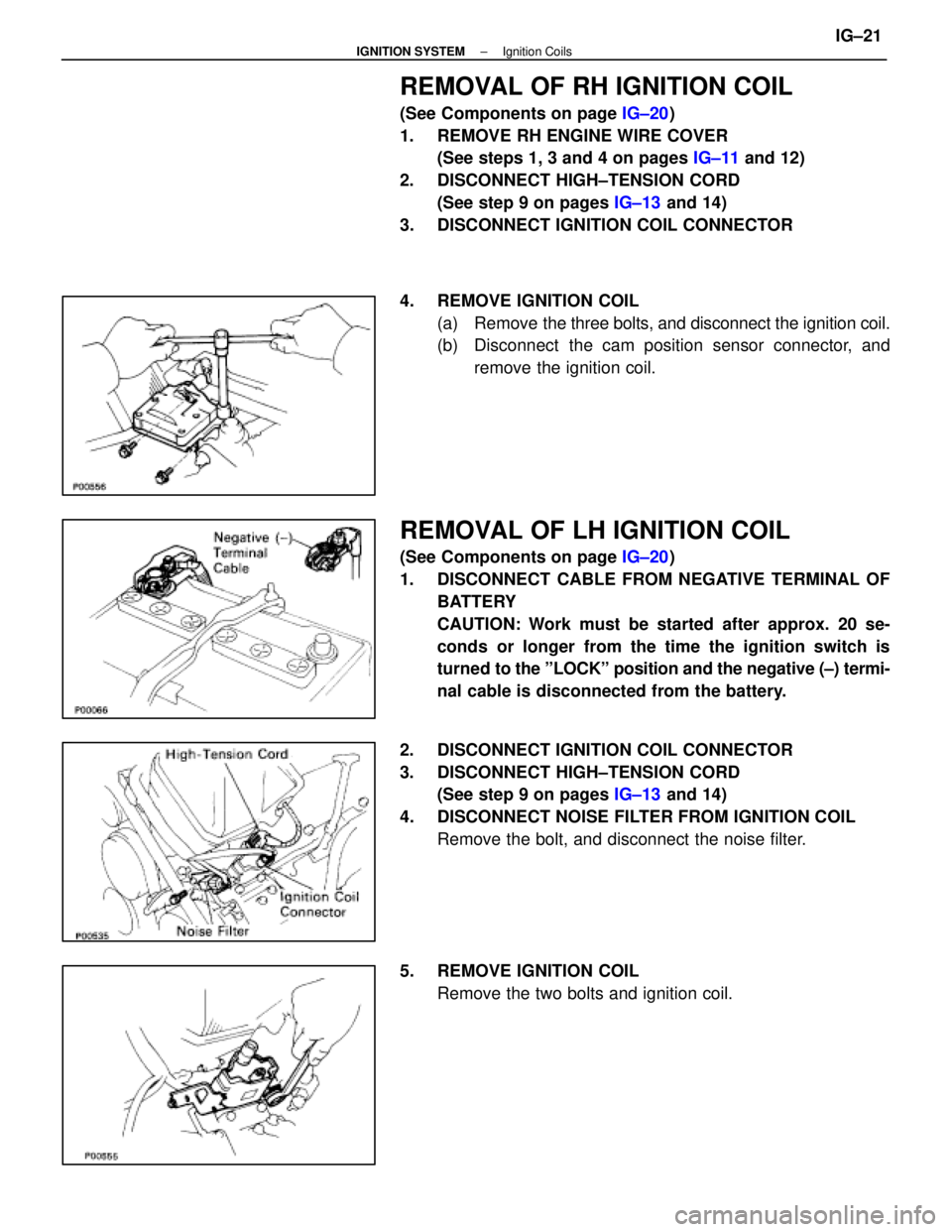
REMOVAL OF RH IGNITION COIL
(See Components on page IG±20)
1. REMOVE RH ENGINE WIRE COVER (See steps 1, 3 and 4 on pages IG±11 and 12)
2. DISCONNECT HIGH±TENSION CORD (See step 9 on pages IG±13 and 14)
3. DISCONNECT IGNITION COIL CONNECTOR
4. REMOVE IGNITION COIL (a) Remove the three bolts, and disconnect the ignition coil.
(b) Disconnect the cam position sensor connector, and
remove the ignition coil.
REMOVAL OF LH IGNITION COIL
(See Components on page IG±20)
1. DISCONNECT CABLE FROM NEGATIVE TERMINAL OF BATTERY
CAUTION: Work must be started after approx. 20 se-
conds or longer from the time the ignition switch is
turned to the ºLOCKº position and the negative (±) termi-
nal cable is disconnected from the battery.
2. DISCONNECT IGNITION COIL CONNECTOR
3. DISCONNECT HIGH±TENSION CORD (See step 9 on pages IG±13 and 14)
4. DISCONNECT NOISE FILTER FROM IGNITION COIL Remove the bolt, and disconnect the noise filter.
5. REMOVE IGNITION COIL Remove the two bolts and ignition coil.
±
IGNITION SYSTEM Ignition CoilsIG±21
WhereEverybodyKnowsYourName
Page 2110 of 4087
INSTALLATION OF RH IGNITION COIL
(See Components on page IG±20)
1. INSTALL IGNITION COIL (a) Install the ignition coil with the three bolts.
(b) Install the cam position sensor connector to the ignition
coil bracket.
2. CONNECT IGNITION COIL CONNECTOR
3. CONNECT HIGH±TENSION CORD
(See step 4 on pages IG±16 and 17)
4. INSTALL RH ENGINE WIRE COVER (See steps 8, 10, 12 and 13 on pages IG±11 and 12)
INSTALLATION OF LH IGNITION COIL
(See Components on page IG±20)
1. INSTALL IGNITION COIL Install the ignition coil with the two bolts.
2. INSTALL NOISE FILTER TO IGNITION COIL Install the noise filter with the bolt.
3. CONNECT HIGH±TENSION CORD
(See step 4 on pages IG±16 and 17)
4. CONNECT IGNITION COIL CONNECTOR
5. CONNECT CABLE TO NEGATIVE TERMINAL OF BATTERY
IG±22
±
IGNITION SYSTEM Ignition Coils
WhereEverybodyKnowsYourName
Page 2112 of 4087
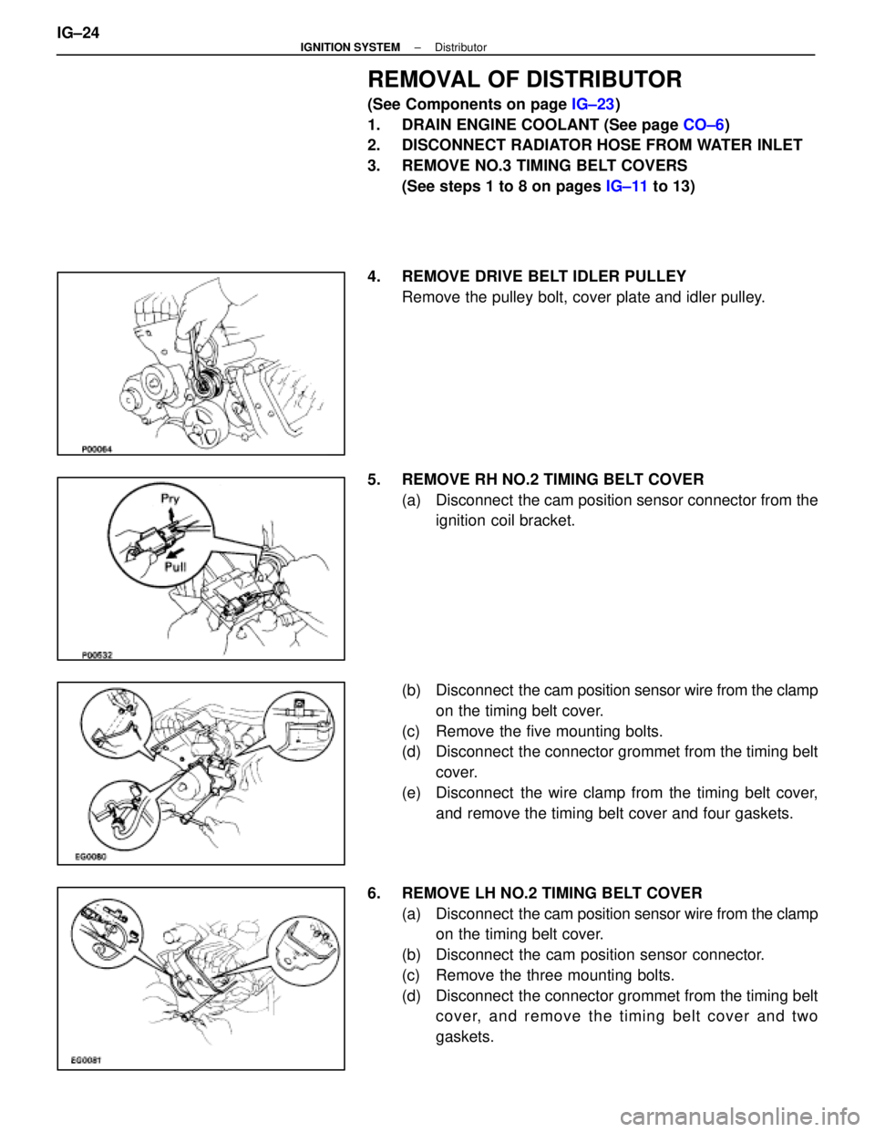
REMOVAL OF DISTRIBUTOR
(See Components on page IG±23)
1. DRAIN ENGINE COOLANT (See page CO±6)
2. DISCONNECT RADIATOR HOSE FROM WATER INLET
3. REMOVE NO.3 TIMING BELT COVERS
(See steps 1 to 8 on pages IG±11 to 13)
4. REMOVE DRIVE BELT IDLER PULLEY Remove the pulley bolt, cover plate and idler pulley.
5. REMOVE RH NO.2 TIMING BELT COVER (a) Disconnect the cam position sensor connector from theignition coil bracket.
(b) Disconnect the cam position sensor wire from the clamp
on the timing belt cover.
(c) Remove the five mounting bolts.
(d) Disconnect the connector grommet from the timing belt cover.
(e) Disconnect the wire clamp from the timing belt cover, and remove the timing belt cover and four gaskets.
6. REMOVE LH NO.2 TIMING BELT COVER (a) Disconnect the cam position sensor wire from the clamp
on the timing belt cover.
(b) Disconnect the cam position sensor connector.
(c) Remove the three mounting bolts.
(d) Disconnect the connector grommet from the timing belt cover, and remove the timing belt cover and two
gaskets.
IG±24
±
IGNITION SYSTEM Distributor
WhereEverybodyKnowsYourName
Page 2116 of 4087
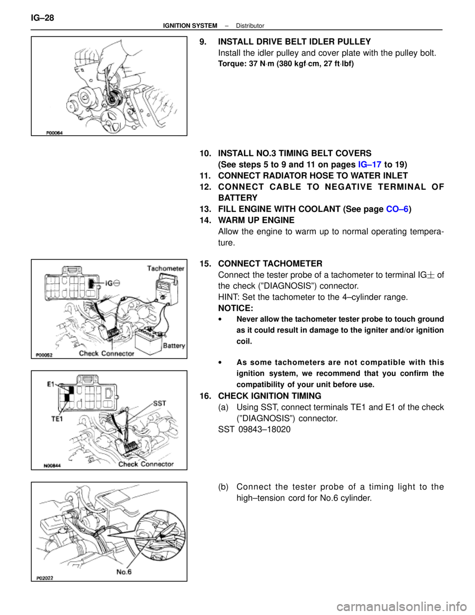
9. INSTALL DRIVE BELT IDLER PULLEYInstall the idler pulley and cover plate with the pulley bolt.
Torque: 37 N Vm (380 kgf Vcm, 27 ft Vlbf)
10. INSTALL NO.3 TIMING BELT COVERS
(See steps 5 to 9 and 11 on pages IG±17 to 19)
11. CONNECT RADIATOR HOSE TO WATER INLET
12. C O N N E C T C A B L E TO N E G AT I V E T E R M I N A L O F BATTERY
13. FILL ENGINE WITH COOLANT (See page CO±6)
14. WARM UP ENGINE Allow the engine to warm up to normal operating tempera-
ture.
15. CONNECT TACHOMETER Connect the tester probe of a tachometer to terminal IG � of
the check (ºDIAGNOSISº) connector.
HINT: Set the tachometer to the 4±cylinder range.
NOTICE:
w Never allow the tachometer tester probe to touch ground
as it could result in damage to the igniter and/or ignition
coil.
w As some tachometers are not compatible with this
ignition system, we recommend that you confirm the
compatibility of your unit before use.
16. CHECK IGNITION TIMING
(a) Using SST, connect terminals TE1 and E1 of the check(ºDIAGNOSISº) connector.
SST 09843±18020
(b) C onnect the tester probe of a timing light to the
high±tension cord for No.6 cylinder.
IG±28
±
IGNITION SYSTEM Distributor
WhereEverybodyKnowsYourName