Page 2145 of 4087

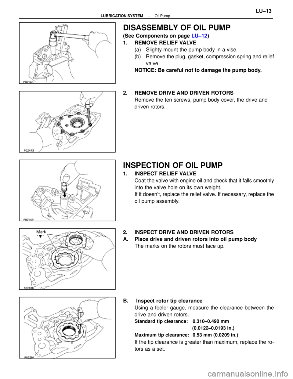
DISASSEMBLY OF OIL PUMP
(See Components on page LU±12)
1. REMOVE RELIEF VALVE (a) Slighty mount the pump body in a vise.
(b) Remove the plug, gasket, compression spring and reliefvalve.
NOTICE: Be careful not to damage the pump body.
2. REMOVE DRIVE AND DRIVEN ROTORS Remove the ten screws, pump body cover, the drive and
driven rotors.
INSPECTION OF OIL PUMP
1. INSPECT RELIEF VALVECoat the valve with engine oil and check that it falls smoothly
into the valve hole on its own weight.
If it doesn't, replace the relief valve. If necessary, replace the
oil pump assembly.
2. INSPECT DRIVE AND DRIVEN ROTORS
A. Place drive and driven rotors into oil pump body The marks on the rotors must face up.
B. Inspect rotor tip clearance Using a feeler gauge, measure the clearance between the
drive and driven rotors.
Standard tip clearance: 0.310±0.490 mm
(0.0122±0.0193 in.)
Maximum tip clearance: 0.53 mm (0.0209 in.)
If the tip clearance is greater than maximum, replace the ro-
tors as a set.
±
LUBRICATION SYSTEM Oil PumpLU±13
WhereEverybodyKnowsYourName
Page 2150 of 4087
6. INSTALL OIL LEVEL SENSOR(a) Install a new gasket to the level sensor.
(b) Install the level sensor with the four bolts.
Torque: 5.4 N Vm (55 kgf Vcm, 48 in. Vlbf)
(c) Connect the level sensor connector.
7. INSTALL OIL DIPSTICK GUIDE AND DIPSTICK (a) Install a new O±ring on the dipstick guide.
(b) Apply soapy water on the O±ring.
(c) Push in the dipstick guide into the guide hole of the No.1
oil pan.
(d) Install the guide with the mounting bolt.
8. INSTALL CRANKSHAFT TIMING PULLEY AND IDLER PULLEY
(See steps 1 and 2 on page EM±29)
9. INSTALL TIMING BELT (See steps 3 to 14 on pages EM±29 to 33)
10. REMOVE ENGINE STAND FROM ENGINE
11. ASSEMBLE ENGINE AND TRANSMISSION (See page EM±103)
12. INSTALL ENGINE WITH TRANSMISSION (See pages EM±104 to 112)
LU±18
±
LUBRICATION SYSTEM Oil Pump
WhereEverybodyKnowsYourName
Page 2151 of 4087

SERVICE SPECIFICATIONS
SERVICE DATA
MA002±0B����� �
����
�
����
�
����
�
����
�����
Engine���������� �
���������
�
���������
�
���������
�
���������
����������
Spark plug
Recommended spark plug
Correct electrode gap
Firing order
Valve clearance������ �
�����
�
�����
�
�����
�
�����
������
ND
NGK
Intake
Exhaust
������������������\
�
�����������������
�
�����������������
�
�����������������
�
�����������������
������������������\
PK20R11
BKR6EP11
1.1 mm (0.043 in.)
1 ± 8 ± 4 ± 3 ± 6 ± 5 ± 7 ± 2
0.15 ± 0.25 mm (0.006 ± 0.010 in.)
0.25 ± 0.35 mm (0.010 ± 0.014 in.)
����� �
����
�
����
�
����
�����
BrakeFront and rear brakes
Pad thickness
Disc thickness
Limit
Limit (Front) (Rear)1.0 mm (0.039 in.)
30.0 mm (1.181 in.)
15.0 mm (0.591 in.)
����� �
����
�
����
�����
Disc runout
Parking brake
Lining thickness
Drum inside diameter
()
Limit
Limit
Limit
()
0.05 mm (0.0020 in.)
1.0 mm (0.039 in.)
191 mm (7.520 in.)
����� �����ChassisSteering linkage
Steering wheel freeplay
Limit30 mm (1.18 in.)����� �
����
�����
gy
Ball joint
Vertical play
Limit
()
0.3 mm (0.012 in.)
MA002±0B
TORQUE SPECIFICATIONS
������������������\
�� ������������������\
��Part tightened������� �������N
Vm������ ������kgf Vcm������ ������ft Vlbf
���������������� ����������������Spark plug x Cylinder head1818013
���������������� ����������������Front seat x Body3737527
���������������� ����������������Front suspension crossmember x Body����� �����for nut1271,30094
���������������� ��������������������� �����for bolt 201
,
2,050148
���������������� ����������������Rear suspension member x Body1761,800130
���������������� ����������������Rear suspension member rear cushion x Body3839028
±
MAINTENANCE (1UZ ± FE)MA±21
WhereEverybodyKnowsYourName
Page 2152 of 4087
MAINTENANCE
GENERAL NOTES:
wThere are 2 separate maintenance schedules,
namely A and B, which apply to different driving
conditions. Find out how the vehicle is driven,
select the appropriate schedule and service the
vehicle accordingly.
w Every service item in the periodic maintenance list
must be performed.
w Next to the columns of periods in the schedule,
reference pages have been added for easy access
to service data and procedures necessary for each
operation.
w The service interval for scheduled maintenance is
determined by the odometer reading or time
interval, whichever comes first, shown in the
schedule.
w Maintenance services after the last period should
be performed at the same interval as before unless
otherwise noted.
w Skipping even 1 item in the list can cause the
engine to run poorly and increase exhaust
emissions.
MA±1
WhereEverybodyKnowsYourName
Page 2156 of 4087

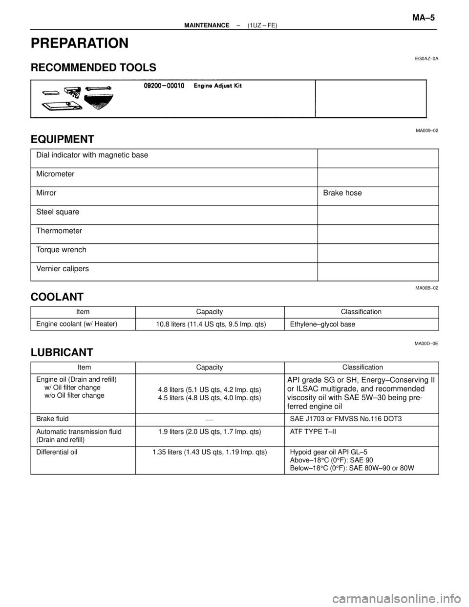
PREPARATION
EG0AZ±0A
RECOMMENDED TOOLS
MA009±02
EQUIPMENT
������������������\
������� �
������������������\
������
������������������\
�������Dial indicator with magnetic base������������ �
�����������
������������
������������������\
������� ������������������\
�������Micrometer
������������������\
������� �
������������������\
������
������������������\
�������MirrorBrake hose
������������������\
������� �
������������������\
������
������������������\
�������
Steel square
������������������\
������� ������������������\
�������Thermometer
������������������\
������� �
������������������\
������
������������������\
�������Torque wrench
������������������\
������� ������������������\
�������Vernier calipers
MA00B±02
COOLANT���������� �
���������Item
�������������� �
�������������Capacity
�������������� �
�������������Classification���������� �
���������
����������Engine coolant (w/ Heater)10.8 liters (11.4 US qts, 9.5 lmp. qts)Ethylene±glycol base
MA00D±0E
LUBRICANT
���������� ����������Item�������������� ��������������Capacity�������������� ��������������Classification���������� �
���������
����������Engine oil (Drain and refill)
w/ Oil filter change
/ Oil filt h
�������������� �
�������������
��������������4.8 liters (5.1 US qts, 4.2 lmp. qts)
�������������� �
�������������
��������������API grade SG or SH, Energy±Conserving II
or ILSAC multigrade, and recommended
���������� �
���������
����������
g
w/o Oil filter change�������������� �
�������������
��������������
4.8 liters (5.1 US qts, 4.2 lm. qts)
4.5 liters (4.8 US qts, 4.0 lmp. qts)�������������� �
�������������
��������������
or ILSAC multigrade, and recommended
viscosity oil with SAE 5W±30 being pre-
ferred engine oil
���������� ����������Brake fluid�������������� ���������������������������� ��������������SAE J1703 or FMVSS No.116 DOT3
���������� ����������Automatic transmission fluid�������������� ��������������1.9 liters (2.0 US qts, 1.7 lmp. qts)�������������� ��������������ATF TYPE T±II
����������
Automatic transmission fluid
(Drain and refill)��������������
1.9 liters (2.0 US qts, 1.7 lm . qts)
��������������
AT F TYPE TII
���������� �
���������
�
���������
����������
Differential oil�������������� �
�������������
�
�������������
��������������
1.35 liters (1.43 US qts, 1.19 lmp. qts)�������������� �
�������������
�
�������������
��������������
Hypoid gear oil API GL±5
Above±18
5C (0 5F): SAE 90
Below±18 5C (0 5F): SAE 80W±90 or 80W
±
MAINTENANCE (1UZ ± FE)MA±5
WhereEverybodyKnowsYourName
Page 2157 of 4087

MAINTENANCE OPERATIONS
MA035±04
ENGINE
Cold Engine Operations
1. REPLACE TIMING BELT
(a) Remove the timing belt.(See page EG±46)
(b) Install the timing belt. (See page EG±59)
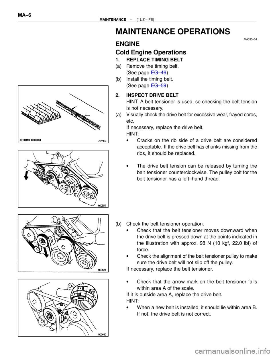
2. INSPECT DRIVE BELT HINT: A belt tensioner is used, so checking the belt tension
is not necessary.
(a) Visually check the drive belt for excessive wear, frayed cords,
etc.
If necessary, replace the drive belt.
HINT:
w Cracks on the rib side of a drive belt are considered
acceptable. If the drive belt has chunks missing from the
ribs, it should be replaced.
w The drive belt tension can be released by turning the
belt tensioner counterclockwise. The pulley bolt for the
belt tensioner has a left±hand thread.
(b) Check the belt tensioner operation. wCheck that the belt tensioner moves downward when
the drive belt is pressed down at the points indicated in
the illustration with approx. 98 N (10 kgf, 22.0 lbf) of
force.
w Check the ali gnment of the belt tensioner pulley to make
sure the drive belt will not slip off the pulley.
If necessary, replace the belt tensioner.
w Check that the arrow mark on the belt tensioner falls
within area A of the scale.
If it is outside area A, replace the drive belt.
HINT:
w When a new belt is installed, it should lie within area B.
If not, the drive belt is not correct.
MA±6
±
MAINTENANCE (1UZ ± FE)
WhereEverybodyKnowsYourName
Page 2160 of 4087

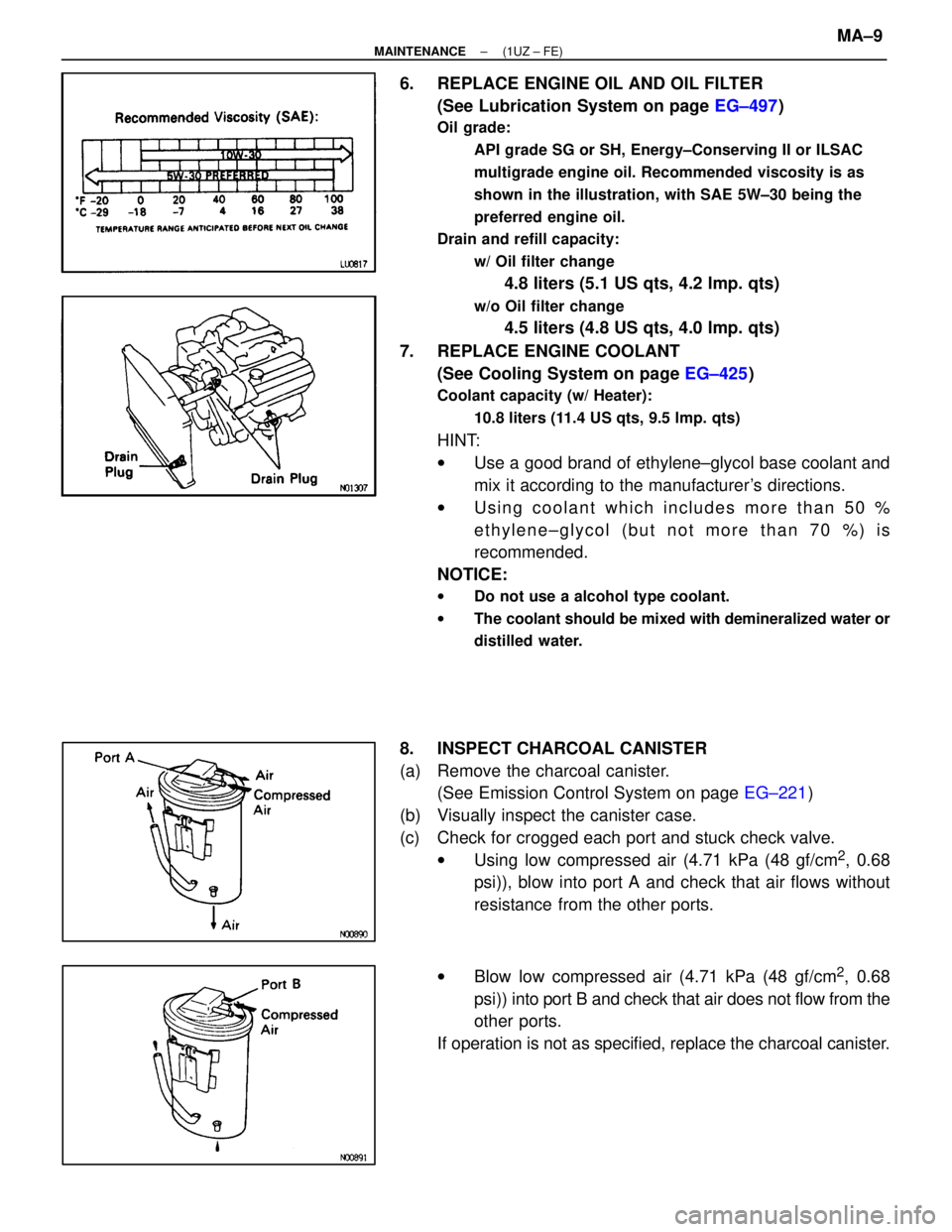
6. REPLACE ENGINE OIL AND OIL FILTER(See Lubrication System on page EG±497)
Oil grade:
API grade SG or SH, Energy±Conserving II or ILSAC
multigrade engine oil. Recommended viscosity is as
shown in the illustration, with SAE 5W±30 being the
preferred engine oil.
Drain and refill capacity:
w/ Oil filter change
4.8 liters (5.1 US qts, 4.2 lmp. qts)
w/o Oil filter change
4.5 liters (4.8 US qts, 4.0 lmp. qts)
7. REPLACE ENGINE COOLANT (See Cooling System on page EG±425)
Coolant capacity (w/ Heater):
10.8 liters (11.4 US qts, 9.5 lmp. qts)
HINT:
wUse a good brand of ethylene±glycol base coolant and
mix it according to the manufacturer's directions.
w Using coolant which includes more than 50 %
ethylene±glycol (but not more than 70 %) is
recommended.
NOTICE:
w Do not use a alcohol type coolant.
w The coolant should be mixed with demineralized water or
distilled water.
8. INSPECT CHARCOAL CANISTER
(a) Remove the charcoal canister.
(See Emission Control System on page EG±221)
(b) Visually inspect the canister case.
(c) Check for crogged each port and stuck check valve. wUsing low compressed air (4.71 kPa (48 gf/cm
2, 0.68
psi)), blow into port A and check that air flows without
resistance from the other ports.
w Blow low compressed air (4.71 kPa (48 gf/cm
2, 0.68
psi)) into port B and check that air does not flow from the
other ports.
If operation is not as specified, replace the charcoal canister.
±
MAINTENANCE (1UZ ± FE)MA±9
WhereEverybodyKnowsYourName
Page 2161 of 4087

(d) Clean the filter in the canister.Clean the filter by blowing 294 kPa (3 kgf/cm
2, 43 psi) of com-
pressed air into port A while holding port B closed.
NOTICE:
w Do not attempt to wash the canister.
w No activated carbon should come out.
(e) Reinstall the charcoal canister.
(See Emission Control System on page EG±222)
9. REPLACE GASKET IN FUEL TANK CAP
(a) Remove the old gasket from the tank cap. Do not damage the
cap.
(b) Install a new gasket by hand.
(c) Check the cap for damage or cracks.
(d) Install the cap and check the torque limiter.
10. INSPECT FUEL LINES AND CONNECTIONS Visually check the fuel lines for cracks, leakage, loose con-
nections, deformation or tank band looseness.
11. INSPECT EXHAUST PIPES AND MOUNTINGS Visually check the pipes, hangers and connections for se-
vere corrosion, leaks or damage.
12. ADJUST VALVE CLEARANCE (See Engine Mechanical on page EG±14)
Valve clearance (Cold):
Intake
.15 ± 0.25 mm (0.006 ± 0.010 in.)
Exhaust
.25 ± 0.35 mm (0.010 ± 0.014 in.)
MA±10
±
MAINTENANCE (1UZ ± FE)
WhereEverybodyKnowsYourName