Page 2127 of 4087
REPLACEMENT OF ENGINE OIL
AND OIL FILTER
CAUTION:
wProlonged and repeated contact with mineral oil will
result in the removal of natural fats from the skin, leading
to dryness, irritation and dermatitis. In addition, used
engine oil contains potentially harmful contaminants
which may cause skin cancer.
w Exerise caution in order to minimize the length and
frequency of contact of your skin to used oil. Wear
protective clothing and gloves. The skin s hould be
thoroughly w ashed with soap and water, or use waterless
hand cleaner, to remove any used engine oil. Do not use
gasoline, thinners, or solvents.
w In order to preserve the environment, used oil and used
oil filter must be disposed of only at designated disposal
sites.
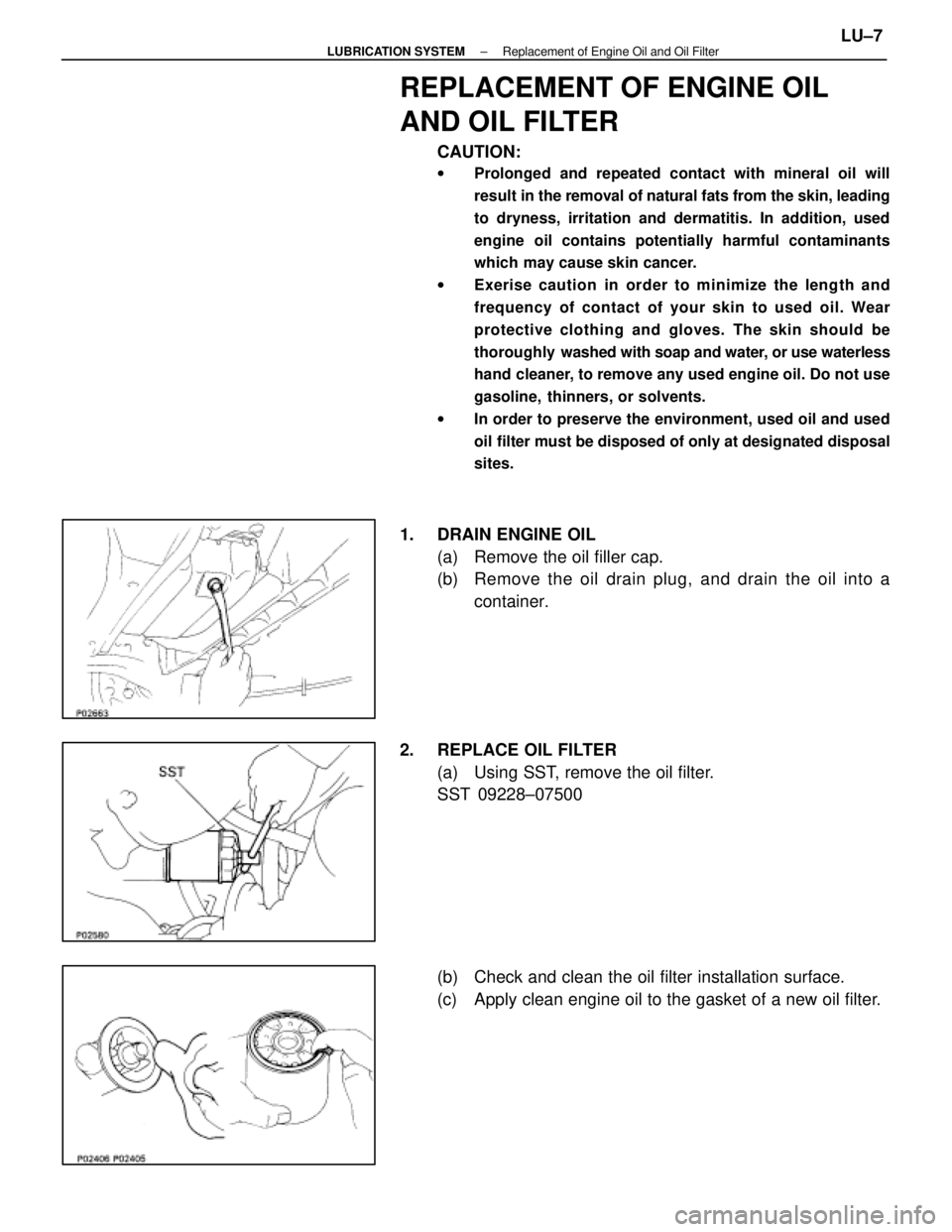
1. DRAIN ENGINE OIL
(a) Remove the oil filler cap.
(b) Remove the oil drain plug, and drain the oil into acontainer.
2. REPLACE OIL FILTER (a) Using SST, remove the oil filter.
SST 09228±07500
(b) Check and clean the oil filter installation surface.
(c) Apply clean engine oil to the gasket of a new oil filter.
±
LUBRICATION SYSTEM Replacement of Engine Oil and Oil FilterLU±7
WhereEverybodyKnowsYourName
Page 2128 of 4087
(d) Lightly screw the oil filter into place, and tighten it untilthe gasket contacts the seat.
(e) Using SST, tighten it an additional 3/4 turn.
SST 09228±07500
3. FILL WITH ENGINE OIL (a) Clean and install the oil drain plug with a new gasket.
Torque: 45 N Vm (450 kgf Vcm, 33 ft Vlbf)
(b) Fill with fresh engine oil.
Oil grade: See page LU±5
Capacity:
Drain and refill w/ Oil filter change
4.8 liters (5.1 US qts, 4.2 lmp. qts)
w/o Oil filter change
4.5 liters (4.8 US qts, 4.0 lmp. qts)
Dry fill 5.2 liters (5.5 US qts, 4.6 lmp. qts)
(c) Reinstall the oil filler cap.
4. START ENGINE AND CHECK FOR LEAKS
5. RECHECK ENGINE OIL LEVEL (See page LU±5)
LU±8
±
LUBRICATION SYSTEM Replacement of Engine Oil and Oil Filter
WhereEverybodyKnowsYourName
Page 2130 of 4087
REMOVAL OF OIL PUMP
(See Components on page LU±8)
HINT: When repairing the oil pump, the oil pan and strainer
should be removed and cleaned.
1. REMOVE ENGINE WITH TRANSMISSION (See pages EM±118 to 128)
2. SEPARATE ENGINE AND TRANSMISSION (See pages EM±129 to 130)
3. INSTALL ENGINE TO ENGINE STAND FOR REMOVAL
4. REMOVE TIMING BELT (See steps 8 to 35 on pages EM±36 to 43)
5. REMOVE NO.2 IDLER PULLEY, NO.1 IDLER PULLEY AND CRANKSHAFT TIMING PULLEY
(See steps 36 to 38 on page EM±44)
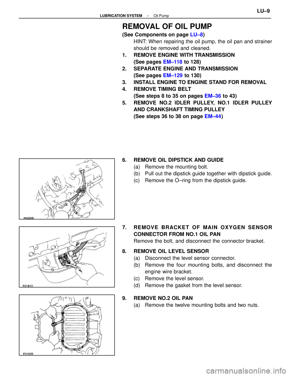
6. REMOVE OIL DIPSTICK AND GUIDE (a) Remove the mounting bolt.
(b) Pull out the dipstick guide together with dipstick guide.
(c) Remove the O±ring from the dipstick guide.
7. REMOVE BRACKET OF MAIN OXYGEN SENSOR CONNECTOR FROM NO.1 OIL PAN
Remove the bolt, and disconnect the connector bracket.
8. REMOVE OIL LEVEL SENSOR (a) Disconnect the level sensor connector.
(b) Remove the four mounting bolts, and disconnect theengine wire bracket.
(c) Remove the level sensor.
(d) Remove the gasket from the level sensor.
9. REMOVE NO.2 OIL PAN (a) Remove the twelve mounting bolts and two nuts.
±
LUBRICATION SYSTEM Oil PumpLU±9
WhereEverybodyKnowsYourName
Page 2132 of 4087
12. REMOVE OIL STRAINERRemove the two bolts, two nuts, oil strainer and gasket.
13. REMOVE OIL FILTER BRACKET (a) Disconnect the oil pressure switch connector.
(b) Remove the two bo lts, stud bolt, the filter bracket and oil
filter assembly.
(c) Remove the gasket from the filter bracket.
14. REMOVE ENGINE SPEED SENSOR (a) Disconnect the speed sensor connector.
(b) Remove the bolt and speed sensor.
15. REMOVE OIL PUMP (a) Remove the eight mounting bolts.
(b) Remove the oil pump by prying the portions between the
cylinder block and oil pump with a screwdriver.
NOTICE: Be careful not to damage the contact surfaces
of the cylinder block and oil pump.
(c) Remove the O±ring from the cylinder block.
±
LUBRICATION SYSTEM Oil PumpLU±11
WhereEverybodyKnowsYourName
Page 2134 of 4087
INSPECTION OF OIL PUMP
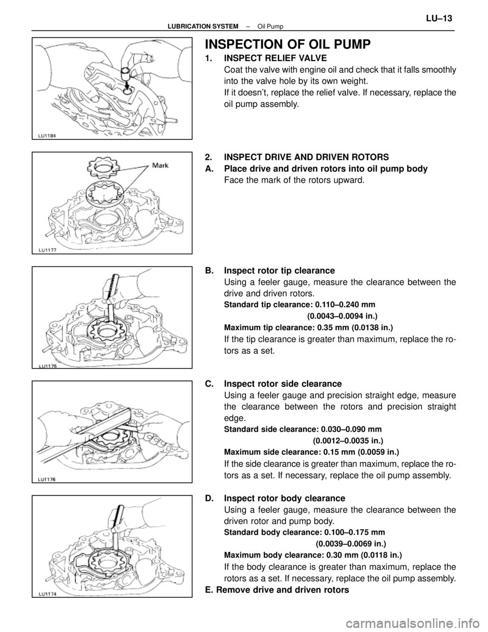
1. INSPECT RELIEF VALVECoat the valve with engine oil and check that it falls smoothly
into the valve hole by its own weight.
If it doesn't, replace the relief valve. If necessary, replace the
oil pump assembly.
2. INSPECT DRIVE AND DRIVEN ROTORS
A. Place drive and driven rotors into oil pump body Face the mark of the rotors upward.
B. Inspect rotor tip clearance Using a feeler gauge, measure the clearance between the
drive and driven rotors.
Standard tip clearance: 0.110±0.240 mm
(0.0043±0.0094 in.)
Maximum tip clearance: 0.35 mm (0.0138 in.)
If the tip clearance is greater than maximum, replace the ro-
tors as a set.
C. Inspect rotor side clearance Using a feeler gauge and precision straight edge, measure
the clearance between the rotors and precision straight
edge.
Standard side clearance: 0.030±0.090 mm
(0.0012±0.0035 in.)
Maximum side clearance: 0.15 mm (0.0059 in.)
If the side clearance is greater than maximum, replace the ro-
tors as a set. If necessary, replace the oil pump assembly.
D. Inspect rotor body clearance Using a feeler gauge, measure the clearance between the
driven rotor and pump body.
Standard body clearance: 0.100±0.175 mm
(0.0039±0.0069 in.)
Maximum body clearance: 0.30 mm (0.0118 in.)
If the body clearance is greater than maximum, replace the
rotors as a set. If necessary, replace the oil pump assembly.
E. Remove drive and driven rotors
±
LUBRICATION SYSTEM Oil PumpLU±13
WhereEverybodyKnowsYourName
Page 2137 of 4087
(e) Install the oil pump with the eight bolts.
Torque:12 mm head 16 N Vm (160 kgf Vcm, 12 ft Vlbf)
14 mm head 30 N Vm (310 kgf Vcm, 22 ft Vlbf)
HINT: Each bolt length is indicated in the illustration.
Bolt length:
A 50 mm (1.97 in.) for 12 mm head
B 106 mm (4.17 in.) for 12 mm head
C 30 mm (1.18 in.) for 12 mm head
D 40 mm (1.57 in.) for 14 mm head
2. INSTALL ENGINE SPEED SENSOR (a) Install the speed sensor with the bolt.
Torque: 6.4 N Vm (65 kgf Vcm, 56 in. Vlbf)
(b) Connect the speed sensor connector.
3. INSTALL OIL FILTER BRACKET (a) Place a new gasket in position on the oil filter bracket.
(b) Install the oil filter bracket with the two bolts and studbolt.
Torque: 18 N Vm (185 kgf Vcm, 13 ft Vlbf)
(c) Connect the oil pressure switch connector.
4. INSTALL OIL STRAINER Install a new gasket and the oil strainer with the two bolts and
two nuts.
Torque: 7.8 N Vm (80 kgf Vcm, 69 in. Vlbf)
LU±16±
LUBRICATION SYSTEM Oil Pump
WhereEverybodyKnowsYourName
Page 2140 of 4087
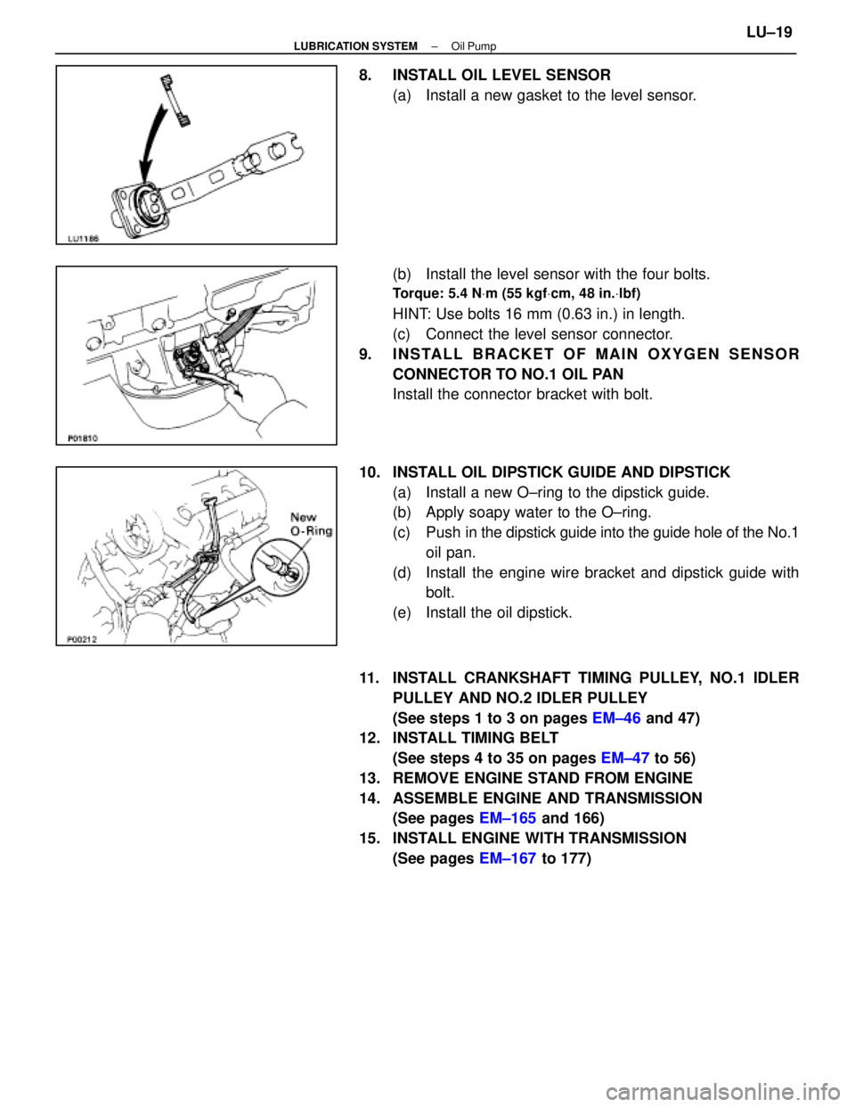
8. INSTALL OIL LEVEL SENSOR(a) Install a new gasket to the level sensor.
(b) Install the level sensor with the four bolts.
Torque: 5.4 N Vm (55 kgf Vcm, 48 in. Vlbf)
HINT: Use bolts 16 mm (0.63 in.) in length.
(c) Connect the level sensor connector.
9. INSTALL BRACKET OF MAIN OXYGEN SENSOR CONNECTOR TO NO.1 OIL PAN
Install the connector bracket with bolt.
10. INSTALL OIL DIPSTICK GUIDE AND DIPSTICK (a) Install a new O±ring to the dipstick guide.
(b) Apply soapy water to the O±ring.
(c) Push in the dipstick guide into the guide hole of the No.1
oil pan.
(d) Install the engine wire bracket and dipstick guide with bolt.
(e) Install the oil dipstick.
11. INSTALL CRANKSHAFT TIMING PULLEY, NO.1 IDLER PULLEY AND NO.2 IDLER PULLEY
(See steps 1 to 3 on pages EM±46 and 47)
12. INSTALL TIMING BELT
(See steps 4 to 35 on pages EM±47 to 56)
13. REMOVE ENGINE STAND FROM ENGINE
14. ASSEMBLE ENGINE AND TRANSMISSION (See pages EM±165 and 166)
15. INSTALL ENGINE WITH TRANSMISSION (See pages EM±167 to 177)
±
LUBRICATION SYSTEM Oil PumpLU±19
WhereEverybodyKnowsYourName
Page 2142 of 4087
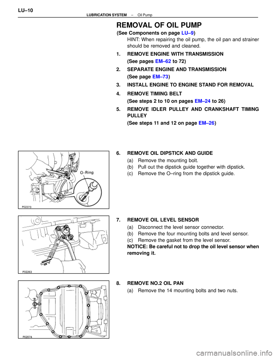
REMOVAL OF OIL PUMP
(See Components on page LU±9)
HINT: When repairing the oil pump, the oil pan and strainer
should be removed and cleaned.
1. REMOVE ENGINE WITH TRANSMISSION (See pages EM±62 to 72)
2. SEPARATE ENGINE AND TRANSMISSION (See page EM±73)
3. INSTALL ENGINE TO ENGINE STAND FOR REMOVAL
4. REMOVE TIMING BELT (See steps 2 to 10 on pages EM±24 to 26)
5. REMOVE IDLER PULLEY AND CRANKSHAFT TIMING PULLEY
(See steps 11 and 12 on page EM±26)
6. REMOVE OIL DIPSTICK AND GUIDE (a) Remove the mounting bolt.
(b) Pull out the dipstick guide together with dipstick.
(c) Remove the O±ring from the dipstick guide.
7. REMOVE OIL LEVEL SENSOR (a) Disconnect the level sensor connector.
(b) Remove the four mounting bolts and level sensor.
(c) Remove the gasket from the level sensor.
NOTICE: Be careful not to drop the oil level sensor when
removing it.
8. REMOVE NO.2 OIL PAN (a) Remove the 14 mounting bolts and two nuts.
LU±10
±
LUBRICATION SYSTEM Oil Pump
WhereEverybodyKnowsYourName