Page 2218 of 4087
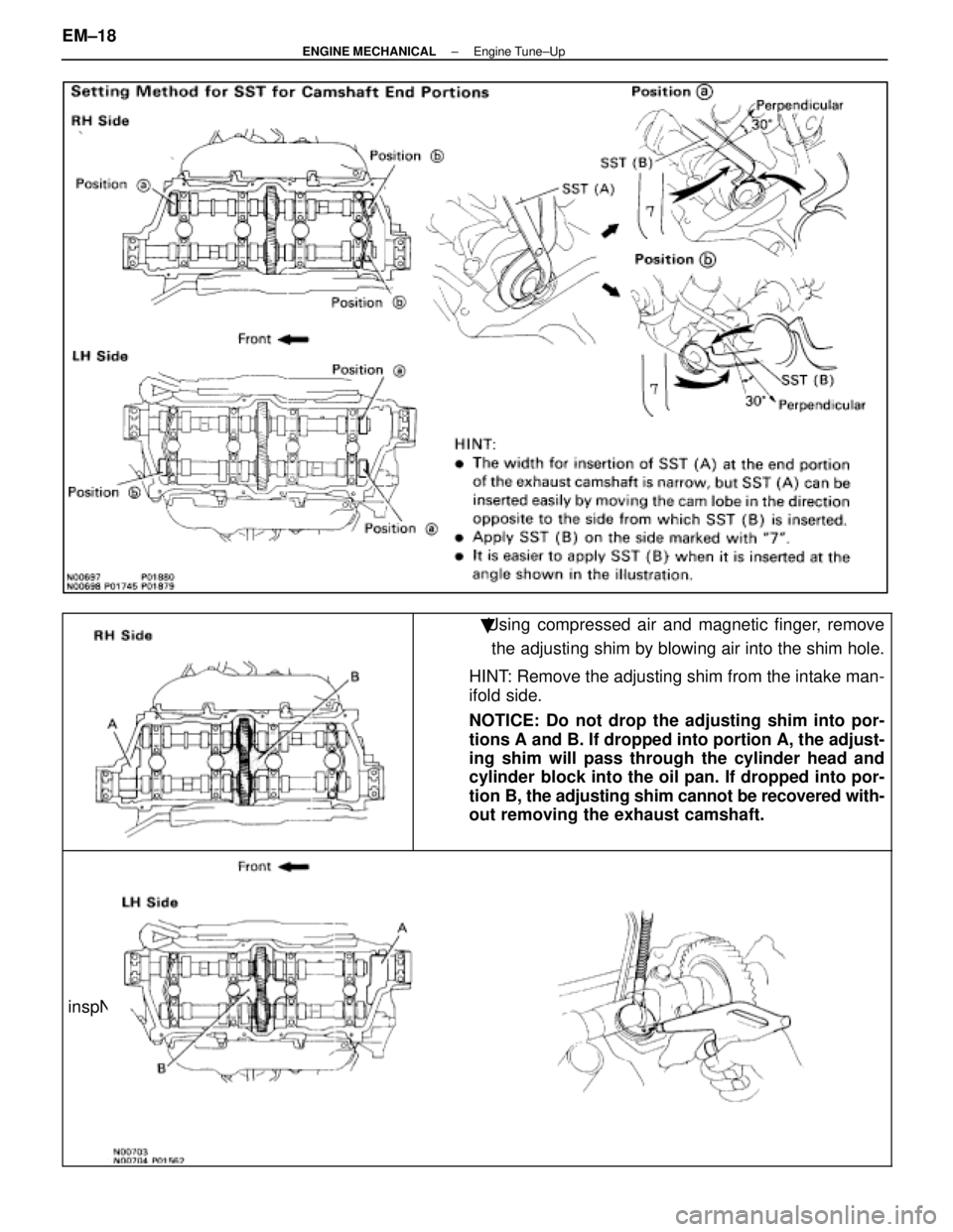
�Using compressed air and magnetic finger, removethe adjusting shim by blowing air into the shim hole.
HINT: Remove the adjusting shim from the intake man-
ifold side.
NOTICE: Do not drop the adjusting shim into por-
tions A and B. If dropped into portion A, the adjust-
ing shim will pass through the cylinder head and
cylinder block into the oil pan. If dropped into por-
tion B, the adjusting shim cannot be recovered with-
out removing the exhaust camshaft.
inspNFO
EM±18±
ENGINE MECHANICAL Engine Tune±Up
WhereEverybodyKnowsYourName
Page 2219 of 4087
(b) Determine the replacement adjusting shim sizefollowing Formula or Charts:
w Using a micrometer, measure the thickness of the
removed shim.
w Calculate the thickness of a new shim so the valve
clearance comes within specified value.
T
Thickness of used shim
A
Measured valve clearance
N
Thickness of new shim
Intake N = T + (A±0.20 mm (0.008 in.))
Exhaust N = T + (A±0.30 mm (0.012 in.))
w Select a new shim with a thickness as close as
possible to the calculated values.
HINT: Shims are available in thirty±three sizes in increments
of 0.025 mm (0.0010 in.), from 2.50 mm (0.0984 in.) to 3.30
mm (0.1299 in.).
(c) Install a new adjusting shim. w Place a new adjusting shim on the valve lifter.
w Press down the valve lifter with SST (A), and
remove SST (B).
SST 09248±55011
(d) Recheck the valve clearance.
±
ENGINE MECHANICAL Engine Tune±UpEM±19
WhereEverybodyKnowsYourName
Page 2220 of 4087
Adjusting Shim Selection Chart (Intake)
EM±20±
ENGINE MECHANICAL Engine Tune±Up
WhereEverybodyKnowsYourName
Page 2221 of 4087
±
ENGINE MECHANICAL Engine Tune±upEM±21
Adjusting
Shim
Selection
Chart
(Exhaust)
WhereEverybodyKnowsYourName
Page 2222 of 4087
 Install the theft deterrent horn with the bolt.
(b) Connect the connector.
24. REINSTALL RH CYLINDER HEAD COVER (a) Remove any oil packing (FIPG) material.")
23. REINSTALL THEFT DETERRENT HORN(a) Install the theft deterrent horn with the bolt.
(b) Connect the connector.
24. REINSTALL RH CYLINDER HEAD COVER (a) Remove any oil packing (FIPG) material.
(b) Apply seal packing to the cylinder head as shown in theillustration.
Seal packing: Part No. 08826±00080 or equivalent
(c) Install the gasket to the cylinder head cover.
(d) Install the seal washer to the mounting bolt.
(e) Install the cylinder head cover with the eight bolts.
Torque: 5.9 N Vm (60 kgf Vcm, 52 in. Vlbf)
(g) Connect the four high±tension cords to the spark plugs.
(h) Install the rear and front high±tension cord clamps with
the two bolts.
HINT: Place the front and rear ends of the front high±tension
cord clamp on the rear high±tension cord clamp and lower
high±tension cord cover.
(i) Fit the high±tension cords to the high±tension cord clamps. (See page IG±16)
25. REINSTALL LH CYLINDER HEAD COVER (a) Remove any oil packing (FIPG) material.
(b) Apply seal packing to the cylinder head as shown in theillustration.
Seal packing: Part No. 08826±00080 or equivalent
EM±22±
ENGINE MECHANICAL Engine Tune±Up
WhereEverybodyKnowsYourName
Page 2223 of 4087
(c) Install the gasket to the cylinder head cover.
(d) Install the seal washer to the mounting bolt.
(e) Install the cylinder head cover with the eight bolts.
Torque: 5.9 NVm (60 kgf Vcm, 52 in. Vlbf)
(f) Connect the two engine wire connectors.
(g) Connect the four injector connectors.
(h) Install the engine wire to the two wire clamps on the
delivery pipe.
(i) Connect the four high±tension cords to the spark plugs.
(j) Install the rear and front high±tension cord clamps with the two bolts.
HINT: Place the front and rear ends of the front high±tension
cord clamp on the rear high±tension cord clamp and lower
high±tension cord cover.
(k) Fit the high±tension cords to the high±tension cord clamps. (See page IG±16)
26. REINSTALL THROTTLE BODY (a) Connect the following hoses:(1) PCV hose from throttle body
(2) Water by±pass hose from throttle body
±
ENGINE MECHANICAL Engine Tune±UpEM±23
WhereEverybodyKnowsYourName
Page 2224 of 4087
(b) Install a new gasket and throttle body with the two boltsand two nuts.
Torque: 18 N Vm (185 kgf Vcm, 13 ft Vlbf)
HINT: Use bolts 40 mm (1.57 in.) in length.
(c) Install the water by±pass pipe (from rear water by±pass
joint) to the clamp on the engine wire cover.
(d) Connect the following hoses: (1) Water by±pass hose to the ISC valve
(2) (USA Spec.) Vacuum hose to throttle body
(3) (Exc. USA Spec.) Three vacuum hoses to throttle body
(e) Connect the following connectors: (1) Throttle position sensor connector
(2) (w/ TRAC) Sub±throttle position sensor connector
(3) (w/ TRAC) Sub±throttle actuator
27. REINSTALL HEATER WATER VALVE (a) Install the water valve and bracket assembly with thetwo bolts.
(b) Install the engine wire clamp with the bolt.
(c) Connect the VSV connector.
EM±24
±
ENGINE MECHANICAL Engine Tune±Up
WhereEverybodyKnowsYourName
Page 2225 of 4087
 Install the three gaskets to the timing belt cover.
(b) Fit portion A of the timing belt cover, matching it with the
lower high±tension cord cover.
(c)")
28. REINSTALL RH NO.3 TIMING BELT COVER(a) Install the three gaskets to the timing belt cover.
(b) Fit portion A of the timing belt cover, matching it with the
lower high±tension cord cover.
(c) Install the timing belt cover with the three bolts.
29. REINSTALL VSV FOR EVAP SYSTEM Install the VSV with the two bolts.
30. REINSTALL LH NO.3 TIMING BELT COVER (a) Install the three gaskets to the timing belt cover.
(b) Install the cord grommet to the high±tension cord.
(c) Install the cord grommet to the timing belt cover.
(d) Fit portion A of the timing belt cover, matching it with the
lower high±tension cord cover.
(e) Install the timing belt cover with the three bolts.
31. RECONNECT PCV HOSE TO LH CYLINDER HEAD
32. RECONNECT FUEL RETURN HOSE TO FUEL RETURN PIPE
33. RECONNECT FUEL INLET HOSE TO LH DELIVERY PIPE Connect the inlet hose with two new gaskets and the
pulsation damper.
SST 09612±24014 (09617±24011)
Torque: 39 N Vm (400 kgf Vcm, 29 ft Vlbf)
33 N Vm (340 kgf Vcm, 24 ft Vlbf) for SST
HINT: Use a torque wrench with a fulcrum length of 30 cm
(11.81 in.)
34. REINSTALL RH ENGINE WIRE COVER (a) Fit portions A and B of the engine wire cover, matchingthem with the lower high±tension cord cover and No.3
timing belt cover.
(b) Install the engine wire cover with the bolt.
±
ENGINE MECHANICAL Engine Tune±UpEM±25
WhereEverybodyKnowsYourName
 Determine the replacement adjusting shim sizefollowing Formula or Charts:
w Using a micrometer, measure the thickness of the
removed shim.
w Calculate the thickness of a new shim so the valve
cle")

EM±20±
ENGINE MECHANICAL Engine Tune±Up
WhereEverybodyKnowsYourName")

WhereEverybodyKnowsYourName")
 Install the gasket to the cylinder head cover.
(d) Install the seal washer to the mounting bolt.
(e) Install the cylinder head cover with the eight bolts.
Torque: 5.9 NVm (60 kgf Vcm, 52 in. V")
 Install a new gasket and throttle body with the two boltsand two nuts.
Torque: 18 N Vm (185 kgf Vcm, 13 ft Vlbf)
HINT: Use bolts 40 mm (1.57 in.) in length.
(c) Install the water by±pass pipe")