Page 1996 of 4087

SERVICE DATA (Cont'd)
ECU (cont'd)Voltage (cont'd)
TerminalsConditionSTD voltage (V)
IGF1E1
IG SW ON1.0 or lessIGF1
IGF2± E1
IdlingPulse generation
G1
G2 G1 (±)
G2 (±)
±IdlingPulse generation
NE ± NE (+)IdlingPulse generation
M±REL ± E1IG SW ON10 ± 14
FPC E1
Cracking, Sudden racing (6,000 rpm)4.2 ± 6.0
FPC ± E1
IdlingPulse generation
DI ± E1Idling7.5 or more
FPU E1
IG SW ON10 ± 14
FPU ± E1
Restarting high temp.2.0 or less
PAG ± E1IG SW ON10 ± 14
ISC1
ISC2
ISC3
ISC4 ± E1
IG SW ON10 ± 14
VF1
VF2
± E1Maintain engine speed at 2,500 rpm for 120 seconds
after warming up then return to idling.1.0 ± 4.0
OXR1
OXL1 ± E1Maintain engine speed at 2,500 rpm for 120 seconds
after warming upPulse generation
(0 ± 1.0)
HTR1
HTR2 E01IG SW ON10 ± 14HTR2
HTL1
HTL2±
E01
E02Idling2.0 or less
EGR1
EGR2
EGR3
EGR4 ± E1
IG SW ON10 ± 14
EGR ± E1Idling10 ± 14
KNK1
KNK2
± E1IdlingPulse generation
NSW E1IG SW ON
Shift position ºPº or ºNº range1.0 or less
NSW ± E1IG SW ON
Ex. shift position ºPº or ºNº range10 ± 14
FI±139EFI SYSTEM
± Service Specifications
WhereEverybodyKnowsYourName
Page 1998 of 4087
SERVICE DATA (Cont'd)
ECU (cont'd)Resistance of wiring connector side (cont'd)
TerminalsConditionSTD voltage (�)
±
HTR1
HTR2
HTL1
HTL2 +B
+B1±5.1 ± 6.3
±
PA G +B
+B1±30 ± 34
±IDL1 +BThrottle valve fully openInfinity
±IDL1
IDL2
+B
+B1Throttle valve fully closed2,300 or less
±VTA1E2
Throttle valve fully open3,300 ± 10,000
±VTA1
VTA2E2
Throttle valve fully closed200 ± 800
VC ± E2±4,000 ± 9,000
THS ± E2Intake air temp, 20
°C (68 °F)2,000 ± 3,000
THW ± E2Coolant temp. 80 °C (176 °F)200 ± 400
THG ± E2EGR gas temp. 50 °C (112 °F)69,400 ± 88,500
G1
G2 G1 (±)
G2 (±)
±Cam position sensor ± 10 ± +40
°C (14 ± 104 °F)835 ± 1,350
NE ± NE (±)engine speed sensor ± 10 ± +40 °C (14 ± 104 °F)835 ± 1,350
Fuel cut rpmw/ Vehicle speed 0 km/h and coolant temp. 80 °C (176 °F)
Fuel cut rpm
Fuel return rpm
1,800 rpm
1,400 rpm
FI±141EFI SYSTEM ± Service Specifications
WhereEverybodyKnowsYourName
Page 2003 of 4087

The EFI system is composed of three basic sub±systems: Fuel, Air Induction and Elect\
ronic Control
Systems.
FUEL SYSTEM
An electric pump fuel pressure supplies sufficient fuel, under a constant pressure, to the EFI injectors. In
accordance with signals from the ECU (Electronic Control Unit), these \
injectors inject the quantity of fuel most
appropriate for the engine condition into the intake manifold.
AIR INDUCTION SYSTEM
The air induction system provides sufficient air for engine operation.
ELECTRONIC CONTROL SYSTEM
The 1UZ±FE engine (ECU±formerly EFI computer) with a microcomputer \
centrally controls the EFI, ESA,
ISC and Diagnosis system, etc. The ECU controls the following functions:
1. Electronic Fuel Injection (EFI)
The ECU receives signals from various sensors indicating changing engine op\
eration conditions such as:Intake air volume
Intake air temperature
Coolant temperature
Engine rpm
Acceleration/deceleration
Exhaust oxygen content etc.
The signals are utilized by the ECU to determine the injection duration nec\
essary for an optimum air±fuel
ratio.
2. Electronic Spark Advance (ESA) The ECU is programmed with data for optimum ignition timing under any and all opera\
ting conditions. Using
data provided by sensors which monitor various engine functions (rpm, coola\
nt temperature, etc.), the
Electronic Control Unit (ECU) triggers the spark at precisely right instant. (S\
ee IG section)
3. Idle Speed Control (ISC) The ECU is programmed with idle speed data for various engine conditions (\
coolant temperature, air condi-
tioner ON/OFF, etc.).
The air volume flowing through the throttle valve by±pass passage is adj\
usted according to the signal from
each sensor and the idle speed is kept at the set value.
4. Diagnosis Function When the ECU detects any malfunctions or abnormalities in the sensor network\
, it lights the ºCHECKº en-
gine warning light in the combination meter. At the same time, the trouble is identified and a diagnostic code
is recorded by the ECU. The diagnostic code can be read by the number of\
blinks of the ºCHECKº engine
warning light when terminals TE1 and E1 are connected. The diagnostic co\
des are refer to the later page.
(See TR section)
5. Self±Correction Function If any sensor malfunctions, an average value recorded in the back±up ci\
rcuit is substituted to make driving
possible.
If danger is predicted, the engine is stopped and the ºCHECKº engine\
warning light will light up.
6. Fail±Safe Function Even if an abnormality occurs in the ECU, the back±up circuit uses a specifie\
d fuel injection and ignition
timing to provide vehicle driveability, and also lightsup the ºCHECKº engine warning light.
FI±4
EFI SYSTEM
± Description
WhereEverybodyKnowsYourName
Page 2006 of 4087
FUEL SYSTEM
Fuel is pumped up by the fuel pump, which flows through the fuel filter unde\
r pressure through the fuel pipe
to the delivery pipe where it is distributed to each injector. The fuel pressure regulator adjusts the pressure of the fuel from the fuel \
line (high pressure side) to a pressure
284 kPa (2.9 kgf/cm2, 41 psi) higher than the pressure inside the intake \
manifold, and excess fuel is returned
to the fuel tank through the return pipe.
When the engine is hot, the fuel pressure is increased to control percolation in the fuel system and impr\
ove
restartability and idling stability.
The pulsation damper absorbs the slight fluctuations in fuel pressure ca\
used by the injector.
The injectors operate on input of injection signals from the ECU and inj\
ect fuel into the intake manifold.
FI±6
±
EFI SYSTEM Operation
WhereEverybodyKnowsYourName
Page 2007 of 4087

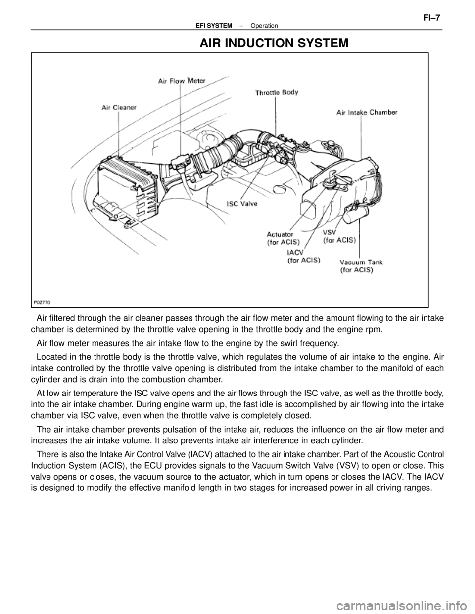
AIR INDUCTION SYSTEM
Air filtered through the air cleaner passes through the air flow meter a\
nd the amount flowing to the air intake
chamber is determined by the throttle valve opening in the throttle body and th\
e engine rpm.
Air flow meter measures the air intake flow to the engine by the swirl f\
requency.
Located in the throttle body is the throttle valve, which regulates the \
volume of air intake to the engine. Air
intake controlled by the throttle valve opening is distributed from the \
intake chamber to the manifold of each
cylinder and is drain into the combustion chamber.
At low air temperature the ISC valve opens and the air flows through the I\
SC valve, as well as the throttle body,
into the air intake chamber. During engine warm up, the fast idle is accomplished by air flowing into the intake
chamber via ISC valve, even when the throttle valve is completely closed.
The air intake chamber prevents pulsation of the intake air, reduces the influence on the air flow meter and
increases the air intake volume. It also prevents intake air interferenc\
e in each cylinder.
There is also the Int ake Air Control Valve (IACV) attached to the air intake chamber. Part of the Acoustic Control
Induction System (ACIS), the ECU provides signals to the Vacuum Switch Valve (VSV) to open or close. This
valve opens or closes, the vacuum source to the actuator, which in turn opens or closes the IACV. The IACV
is designed to modify the effective manifold length in two stages for increased power in all driving\
ranges.
±
EFI SYSTEM OperationFI±7
WhereEverybodyKnowsYourName
Page 2008 of 4087
ELECTRONIC CONTROL SYSTEM
The control system consists of sensors which detect various engine conditio\
ns, and a ECU which determines
the injection volume (timing) based on the signals from the sensors.
The various sensors detect the air intake volume, engine rpm, oxygen densit\
y in the exhaust gas, coolant tem-
perature, air intake temperature and atmospheric pressure etc. and convert the inf\
ormation into an electrical
signal which is sent to the ECU. Based on these signals, the ECU calculates th\
e optimum ignition timing for the
current conditions and operates the injectors.
The ECU not only controls the fuel injection timing, but also the self diag\
nostic function which records the oc-
currence of a malfunction, ignition timing control, idle rpm control, EGR contro\
l, EVAP control, ACIS and fuel
pump control, which switches between the high and low fuel pump speeds accor\
ding to varied load conditions. FI±8
±
EFI SYSTEM Operation
WhereEverybodyKnowsYourName
Page 2011 of 4087

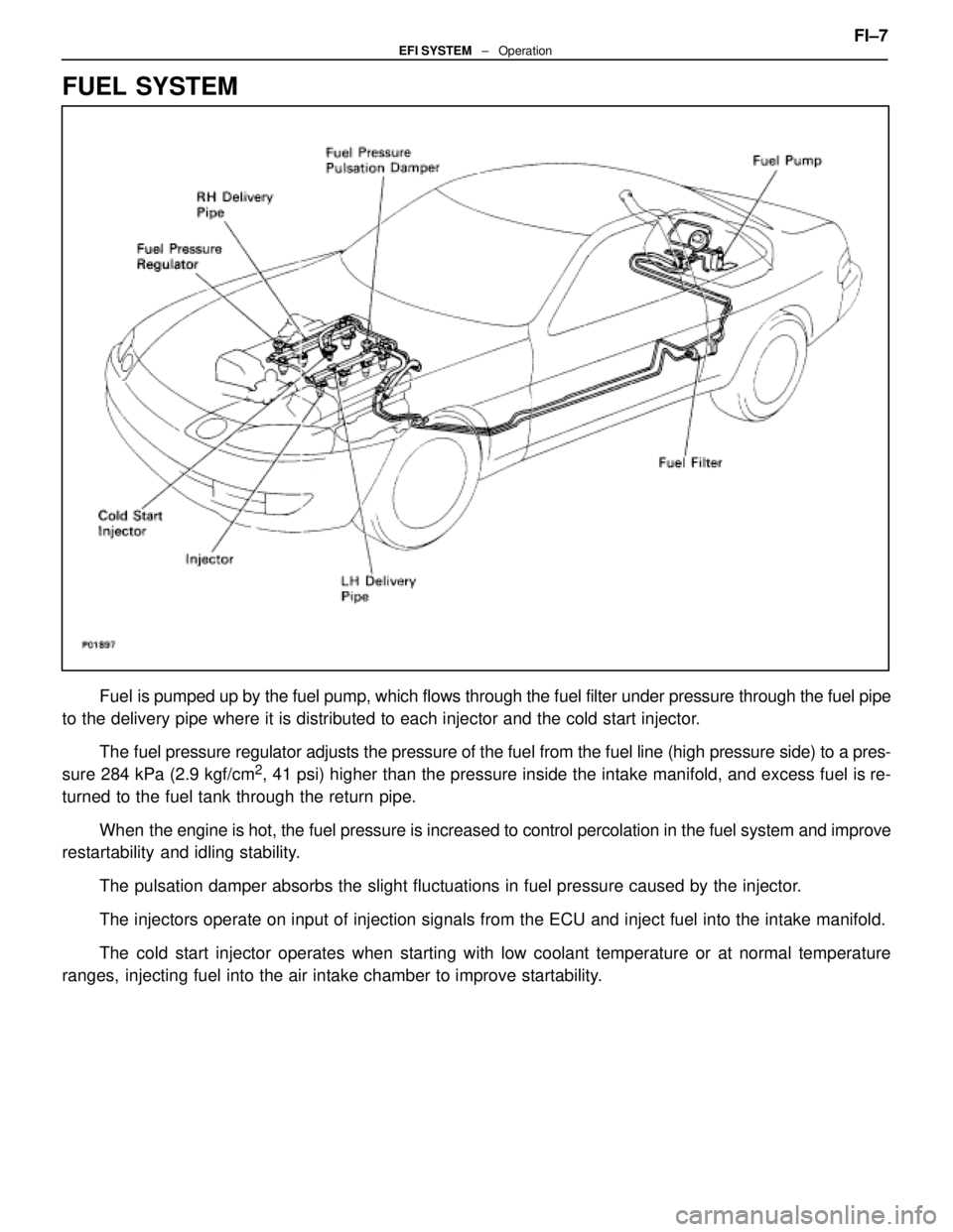
FUEL SYSTEM
Fuel is pumped up by the fuel pump, which flows through the fuel filter under pr\
essure through the fuel pipe
to the delivery pipe where it is distributed to each injector and the cold\
start injector.
The fuel pressure regulator adjusts the pressure of the fuel from the fuel \
line (high pressure side) to a pres-
sure 284 kPa (2.9 kgf/cm
2, 41 psi) higher than the pressure inside the intake manifold, and exce\
ss fuel is re-
turned to the fuel tank through the return pipe.
When the engine is hot, the fuel pressure is increased to control percolatio\
n in the fuel system and improve
restartability and idling stability.
The pulsation damper absorbs the slight fluctuations in fuel pressure ca\
used by the injector.
The injectors operate on input of injection signals from the ECU and inj\
ect fuel into the intake manifold.
The cold start injector operates when starting with low coolant temperature or at normal temperature
ranges, injecting fuel into the air intake chamber to improve startability. FI±7
EFI SYSTEM
± Operation
WhereEverybodyKnowsYourName
Page 2012 of 4087

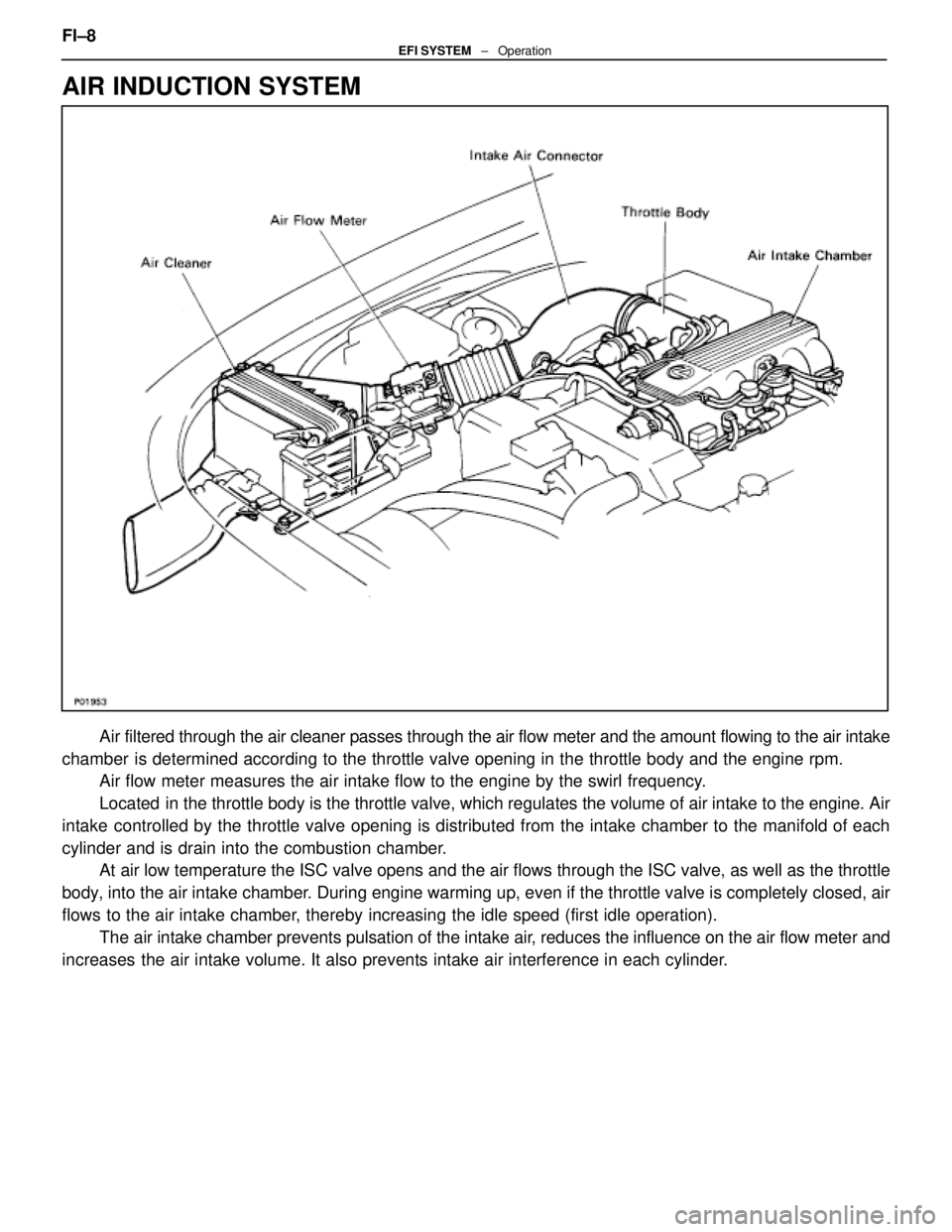
AIR INDUCTION SYSTEM
Air filtered through the air cleaner passes through the air flow meter and \
the amount flowing to the air intake
chamber is determined according to the throttle valve opening in the throttle b\
ody and the engine rpm. Air flow meter measures the air intake flow to the engine by the swirl f\
requency.
Located in the throttle body is the throttle valve, which regulates the volume \
of air intake to the engine. Air
intake controlled by the throttle valve opening is distributed from the intake\
chamber to the manifold of each
cylinder and is drain into the combustion chamber. At air low temperature the ISC valve opens and the air flows through the I\
SC valve, as well as the throttle
body, into the air intake chamber. During engine warming up, even if the throttle valve is completely clo\
sed, air
flows to the air intake chamber, thereby increasing the idle speed (first idle operation). The air intake chamber prevents pulsation of the intake air, reduces the influence on the air flow meter and
increases the air intake volume. It also prevents intake air interference in each\
cylinder. FI±8
EFI SYSTEM ± Operation
WhereEverybodyKnowsYourName