Page 1462 of 4087

35. REMOVE CYLINDER HEAD COVERSRemove the 8 bolts, seal washers, cylinder head cover and
gasket. Remove the 2 cylinder head covers.
36. IF NECESSARY, REMOVE SEMI±CIRCULAR PLUGS
37. REMOVE CAMSHAFTS
NOTICE: Since the thrust clearance of the camshaft is small,
the camshaft must be kept level while it is being removed. If the
camshaft is not kept camshaft is not kept level, the portion of
the cylinder head receiving the shaft thrust may crack or be
damaged, causing the camshaft to seize or break. To avoid
this, the following steps should be carried out.
A. Remove exhaust camshaft from RH cylinder head
(a) Boring the service bolt hole of the driven sub±gear upward by turning the hexagon wrench head portion of the exhaust
camshaft with a wrench.
(b) Secure the exhaust camshaft sub±gear to the drive gear with
a service bolt.
Recommended service bolt: 6 mm for thread diameter
1.0 mm for thread pitch
16 ± 20 mm (0.63 ± 0.79 in.) for bolt length
HINT: When removing the camshaft, make sure that the tor-
sional spring force of the sub±gear has been eliminated by
the above operation.
(c) Set the timing mark (1 dot mark) of the camshaft driven gear at approx. 10 � angle by turning the hexagon wrench head
portion of the exhaust camshaft with a wrench.
EG±86
±
1UZ±FE ENGINE ENGINE MECHANICAL
WhereEverybodyKnowsYourName
Page 1464 of 4087
 Boring the service bolt hole of the driven sub±gear upwardby turning the hexagon wrench head portion of the exhaust
camshaft with a wrench.
(b)")
C. Remove exhaust camshaft from LH cylinder head
(a) Boring the service bolt hole of the driven sub±gear upwardby turning the hexagon wrench head portion of the exhaust
camshaft with a wrench.
(b) Secure the exhaust camshaft sub±gear to drive gear with a service bolt.
Recommended service bolt:6 mm for thread diameter
1.0 mm for thread pitch
16 ± 20 mm (0.63 ± 0.79 in.) for bolt length
HINT: When removing the camshaft, make sure that the tor-
sional spring force of the sub±gear has been eliminated by
the above operation.
(c) Set the timing mark (2 dot marks) of the camshaft drive gear at approx. 15 � angle by turning the hexagon wrench head
portion of the exhaust camshaft with a wrench.
(d) Alternately loosen and remove the 2 bearing cap bolts holding the intake camshaft side of the oil feed pipe to the
cylinder head.
(e) Uniformly loosen and remove the 8 bearing cap bolts in several passes, in the sequence shown.
(f) Remove the oil feed pipe, 4 bearing caps and ex haust
camshaft.
EG±88
±
1UZ±FE ENGINE ENGINE MECHANICAL
WhereEverybodyKnowsYourName
Page 1465 of 4087
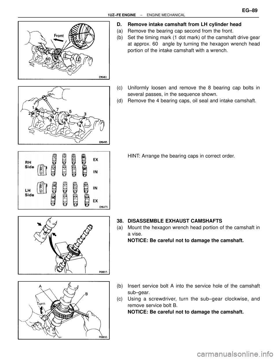
D. Remove intake camshaft from LH cylinder head
(a) Remove the bearing cap second from the front.
(b) Set the timing mark (1 dot mark) of the camshaft drive gearat approx. 60 � angle by turning the hexagon wrench head
portion of the intake camshaft with a wrench.
(c) Uniformly loosen and remove the 8 bearing cap bolts in several passes, in the sequence shown.
(d) Remove the 4 bearing caps, oil seal and intake camshaft.
HINT: Arrange the bearing caps in correct order.
38. DISASSEMBLE EXHAUST CAMSHAFTS
(a) Mount the hexagon wrench head portion of the camshaft in a vise.
NOTICE: Be careful not to damage the camshaft.
(b) Insert service bolt A into the service hole of the camshaft sub±gear.
(c) Using a screwdriver, turn the sub±gear clockwise, and
remove service bolt B.
NOTICE: Be careful not to damage the camshaft.
±
1UZ±FE ENGINE ENGINE MECHANICALEG±89
WhereEverybodyKnowsYourName
Page 1468 of 4087
(b) Lift the cylinder head from the dowels on the cylinder block,and place the 2 cylinder heads on wooden blocks on a bench.
HINT: If the cylinder head is off, pry between the cylinder
head and cylinder block with a screwdriver.
NOTICE: Be careful not to damage the contact surfaces of the
cylinder head and cylinder block.
42. REMOVE EXHAUST MANIFOLD FROM RH CYLINDERHEAD
(a) Remove the 3 bolts and heat insulator.
(b) Remove the main heated oxygen sensor.
(c) Remove the 8 nuts, exhaust manifold and gasket.
43. REMOVE EXHAUST MANIFOLD FROM LH CYLINDER
HEAD
(a) Remove the 3 bolts and heat insulator.
EG±92
±
1UZ±FE ENGINE ENGINE MECHANICAL
WhereEverybodyKnowsYourName
Page 1469 of 4087
(b) Remove the main heated oxygen sensor.
(c) Remove the 8 nuts, exhaust manifold and gasket.
EG11C±06
CYLINDER HEAD DISASSEMBLY
(See Components for Removal and Installation)
1. REMOVE VALVE LIFTERS AND SHIMSHINT: Arrange the valve lifters and shims in correct order.
2. REMOVE VALVES
(a) Using SST, compress the valve spring and remove the 2 keepers.
SST 09202±70010
±
1UZ±FE ENGINE ENGINE MECHANICALEG±93
WhereEverybodyKnowsYourName
Page 1472 of 4087
D. Clean cylinder headUsing a soft brush and solvent, thoroughly clean the cylinder
head.
3. INSPECT CYLINDER HEAD
A. Inspect for flatness Using a precision straight edge and feeler gauge, measure
the surface contacting the cylinder block and the manifolds
for warpage.
Maximum warpage:
0.10 mm (0.0039 in.)
If warpage is greater than maximum, replace the cylinder
head.
B. Inspect for cracks Using a dye penetrant, check the combustion chamber, in-
take ports, exhaust ports and cylinder block surface for
cracks.
If cracked, replace the cylinder head.
4. CLEAN VALVES
(a) Using a gasket scraper, chip off any carbon from the valve head.
(b) Using a wire brush, thoroughly clean the valve.
EG±96
±
1UZ±FE ENGINE ENGINE MECHANICAL
WhereEverybodyKnowsYourName
Page 1473 of 4087
 Using a caliper gauge, measure the inside diameter of theguide bushing.
Bushing inside diameter:
6.010 ± 6.030 mm (0.2366 ± 0.2374 in.)
(b) Using a")
5. INSPECT VALVE STEMS AND GUIDE BUSHINGS
(a) Using a caliper gauge, measure the inside diameter of theguide bushing.
Bushing inside diameter:
6.010 ± 6.030 mm (0.2366 ± 0.2374 in.)
(b) Using a micrometer, measure the diameter of the valve stem.
Valve stem diameter:
Intake5.970 ± 5.985 mm (0.2350 ± 0.2356 in.)
Exhaust 5.965 ± 5.980 mm (0.2348 ± 0.2354 in.)
(c) Subtract the valve stem diameter measurement from the guide bushing inside diameter measurement
Standard oil clearance:
Intake0.025 ± 0.060 mm (0.0010 ± 0.0024 in.)
Exhaust 0.030 ± 0.065 mm (0.0012 ± 0.0026 in.)
Maximum oil clearance: Intake
0.08 mm (0.0031 in.)
Exhaust 0.10 mm (0.0039 in.)
If the clearance is greater than maximum, replace the valve
and guide bushing.
6. IF NECESSARY, REPLACE VALVE GUIDE BUSHINGS
(a) Insert an old valve wrapped with tape into the valve guide bushing, and break off the valve guide bushing by hitting it
with a hammer. Remove the snap ring.
HINT: Wrap the tape approx. 8 mm (0.31 in.) from the valve
stem ends.
NOTICE: Be careful not to damage the valve lifter hole.
±
1UZ±FE ENGINE ENGINE MECHANICALEG±97
WhereEverybodyKnowsYourName
Page 1474 of 4087
 Gradually heat the cylinder head to 80 ± 100�C (176 ±
212 �F).
(c) Using SST and a hammer, tap out the guide bushing. SST 09201±70010
(d) Using a caliper gauge, measure the bushing bore dia")
(b) Gradually heat the cylinder head to 80 ± 100�C (176 ±
212 �F).
(c) Using SST and a hammer, tap out the guide bushing. SST 09201±70010
(d) Using a caliper gauge, measure the bushing bore diameter of the cylinder head.
(e) Select a new guide bushing (STD or O/S 0.05).
Both intake and exhaust
�������� �
�������
��������
Bushing bore diameter mm (in.)������
������
������
Bushing size
�������� ��������11.000 ± 11.027
(0.4331 ± 0.4341)������ ������Use STD
�������� �
�������
��������
11.050 ± 11.077
(0.4350 ± 0.4361)
������
������
������Use O/S 0.05
V00228
If the bushing bore diameter of the cylinder head is greater
than 11.027 mm (0.4341 in.), machine the bushing bore to
the following dimension:
11.050 ± 11.077 mm (0.4350 ± 0.4361 in.)
If the bushing bore diameter of the cylinder head is greater
than 11.077 mm (0.4361 in.), replace the cylinder head.
HINT: Different bushings are used for the intake and exhaust.
EG±98
±
1UZ±FE ENGINE ENGINE MECHANICAL
WhereEverybodyKnowsYourName
 Lift the cylinder head from the dowels on the cylinder block,and place the 2 cylinder heads on wooden blocks on a bench.
HINT: If the cylinder head is off, pry between the cylinder
head and cyli")
 Remove the main heated oxygen sensor.
(c) Remove the 8 nuts, exhaust manifold and gasket.
EG11C±06
CYLINDER HEAD DISASSEMBLY
(See Components for Removal and Installation)
1. REMOVE VALVE LIFT")
