Page 1476 of 4087

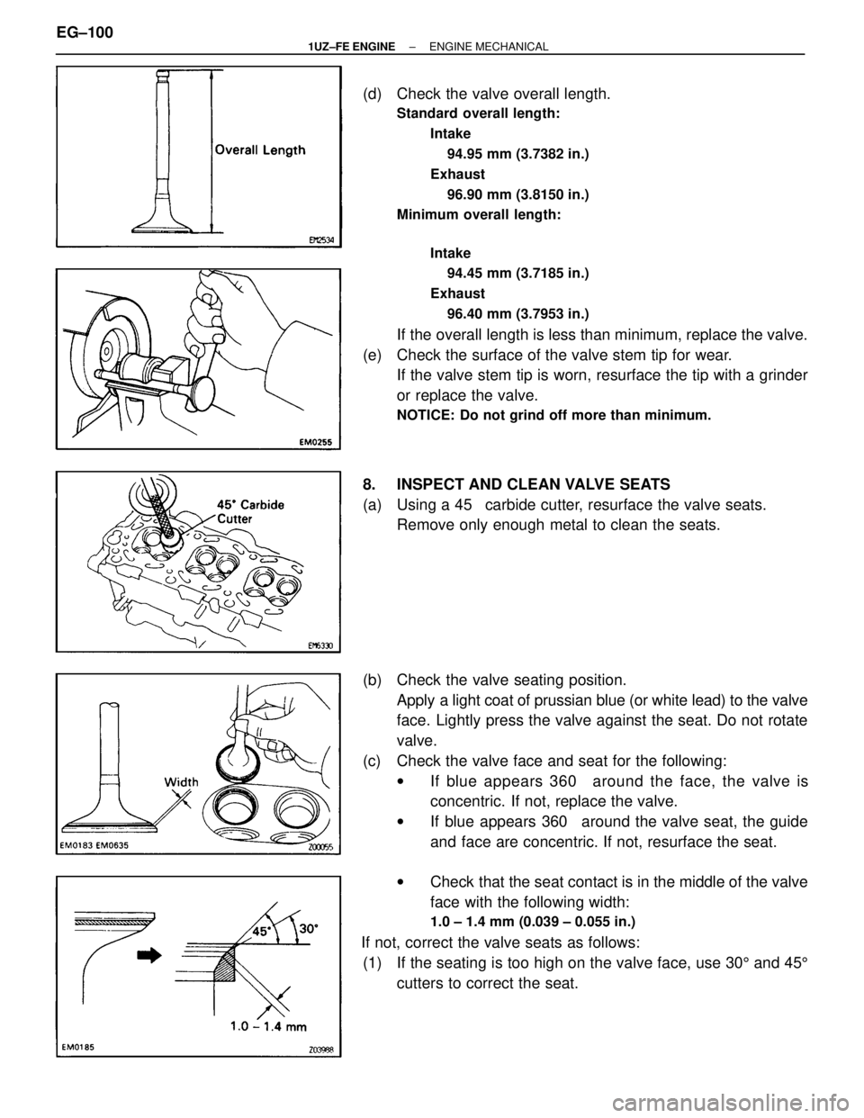
(d) Check the valve overall length.
Standard overall length:Intake94.95 mm (3.7382 in.)
Exhaust 96.90 mm (3.8150 in.)
Minimum overall length:
Intake94.45 mm (3.7185 in.)
Exhaust 96.40 mm (3.7953 in.)
If the overall length is less than minimum, replace the valve.
(e) Check the surface of the valve stem tip for wear. If the valve stem tip is worn, resurface the tip with a grinder
or replace the valve.
NOTICE: Do not grind off more than minimum.
8. INSPECT AND CLEAN VALVE SEATS
(a) Using a 45 � carbide cutter, resurface the valve seats.
Remove only enough metal to clean the seats.
(b) Check the valve seating position. Apply a light coat of prussian blue (or white lead) to the valve
face. Lightly press the valve against the seat. Do not rotate
valve.
(c) Check the valve face and seat for the following: wIf blue appears 360 � around the face, the valve is
concentric. If not, replace the valve.
w If blue appears 360 � around the valve seat, the guide
and face are concentric. If not, resurface the seat.
w Check that the seat contact is in the middle of the valve
face with the following width:
1.0 ± 1.4 mm (0.039 ± 0.055 in.)
If not, correct the valve seats as follows:
(1) If the seating is too high on the valve face, use 30 5 and 45 5
cutters to correct the seat.
EG±100
±
1UZ±FE ENGINE ENGINE MECHANICAL
WhereEverybodyKnowsYourName
Page 1478 of 4087

10. INSPECT CAMSHAFTS AND BEARINGS
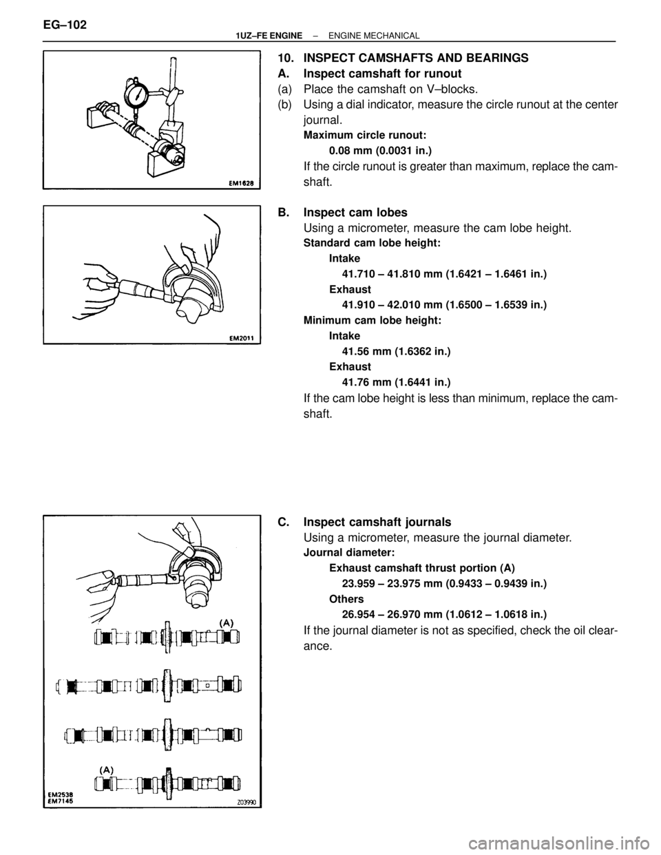
A. Inspect camshaft for runout
(a) Place the camshaft on V±blocks.
(b) Using a dial indicator, measure the circle runout at the centerjournal.
Maximum circle runout:
0.08 mm (0.0031 in.)
If the circle runout is greater than maximum, replace the cam-
shaft.
B. Inspect cam lobes Using a micrometer, measure the cam lobe height.
Standard cam lobe height:
Intake41.710 ± 41.810 mm (1.6421 ± 1.6461 in.)
Exhaust 41.910 ± 42.010 mm (1.6500 ± 1.6539 in.)
Minimum cam lobe height: Intake41.56 mm (1.6362 in.)
Exhaust
41.76 mm (1.6441 in.)
If the cam lobe height is less than minimum, replace the cam-
shaft.
C. Inspect camshaft journals Using a micrometer, measure the journal diameter.
Journal diameter:
Exhaust camshaft thrust portion (A)23.959 ± 23.975 mm (0.9433 ± 0.9439 in.)
Others 26.954 ± 26.970 mm (1.0612 ± 1.0618 in.)
If the journal diameter is not as specified, check the oil clear-
ance.
EG±102
±
1UZ±FE ENGINE ENGINE MECHANICAL
WhereEverybodyKnowsYourName
Page 1480 of 4087
(f) Measure the Plastigage at its widest point.
Standard oil clearance:Exhaust camshaft thrust portion
0.025 ± 0.061 mm (0.0010 ± 0.0024 in.)
Others 0.030 ± 0.067 mm (0.0012 ± 0.0026 in.)
Maximum oil clearance: 0.10 mm (0.0039 in.)
If the oil clearance is greater than maximum, replace the cam-
shaft. If necessary, replace the bearing caps and cylinder
head as a set.
(g) Completely remove the Plastigage.
(h) Remove the camshafts.
G. Inspect camshaft thrust clearance
(a) Install the camshaft. (See step 7 on pages EG±114 to 120)
(b) Using a dial indicator, measure the thrust clearance while moving the camshaft back and forth.
Standard thrust clearance:
0.040 ± 0.090 mm (0.0016 ± 0.0035 in.)
Maximum thrust clearance: 0.12 mm (0.0047 in.)
If the thrust clearance is greater than maximum, replace the
camshaft. If necessary, replace the bearing caps and cylin-
der head as a set.
(c) Remove the camshafts.
EG±104
±
1UZ±FE ENGINE ENGINE MECHANICAL
WhereEverybodyKnowsYourName
Page 1481 of 4087

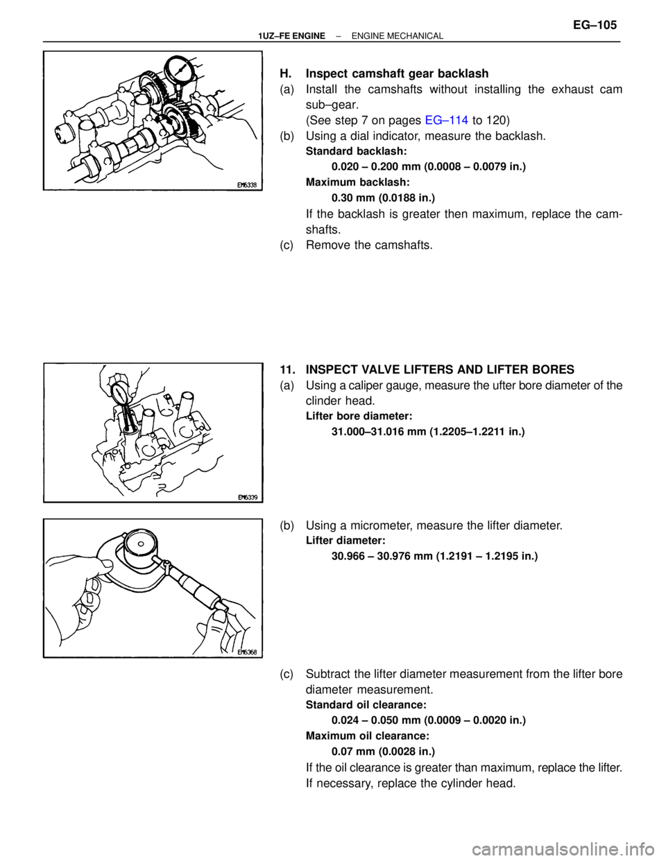
H. Inspect camshaft gear backlash
(a) Install the camshafts without installing the exhaust camsub±gear.
(See step 7 on pages EG±114 to 120)
(b) Using a dial indicator, measure the backlash.
Standard backlash:
0.020 ± 0.200 mm (0.0008 ± 0.0079 in.)
Maximum backlash: 0.30 mm (0.0188 in.)
If the backlash is greater then maximum, replace the cam-
shafts.
(c) Remove the camshafts.
11. INSPECT VALVE LIFTERS AND LIFTER BORES
(a) Using a caliper gauge, measure the ufter bore diameter of the
clinder head.
Lifter bore diameter:
31.000±31.016 mm (1.2205±1.2211 in.)
(b) Using a micrometer, measure the lifter diameter.
Lifter diameter:30.966 ± 30.976 mm (1.2191 ± 1.2195 in.)
(c) Subtract the lifter diameter measurement from the lifter borediameter measurement.
Standard oil clearance:
0.024 ± 0.050 mm (0.0009 ± 0.0020 in.)
Maximum oil clearance: 0.07 mm (0.0028 in.)
If the oil clearance is greater than maximum, replace the lifter.
If necessary, replace the cylinder head.
±
1UZ±FE ENGINE ENGINE MECHANICALEG±105
WhereEverybodyKnowsYourName
Page 1482 of 4087

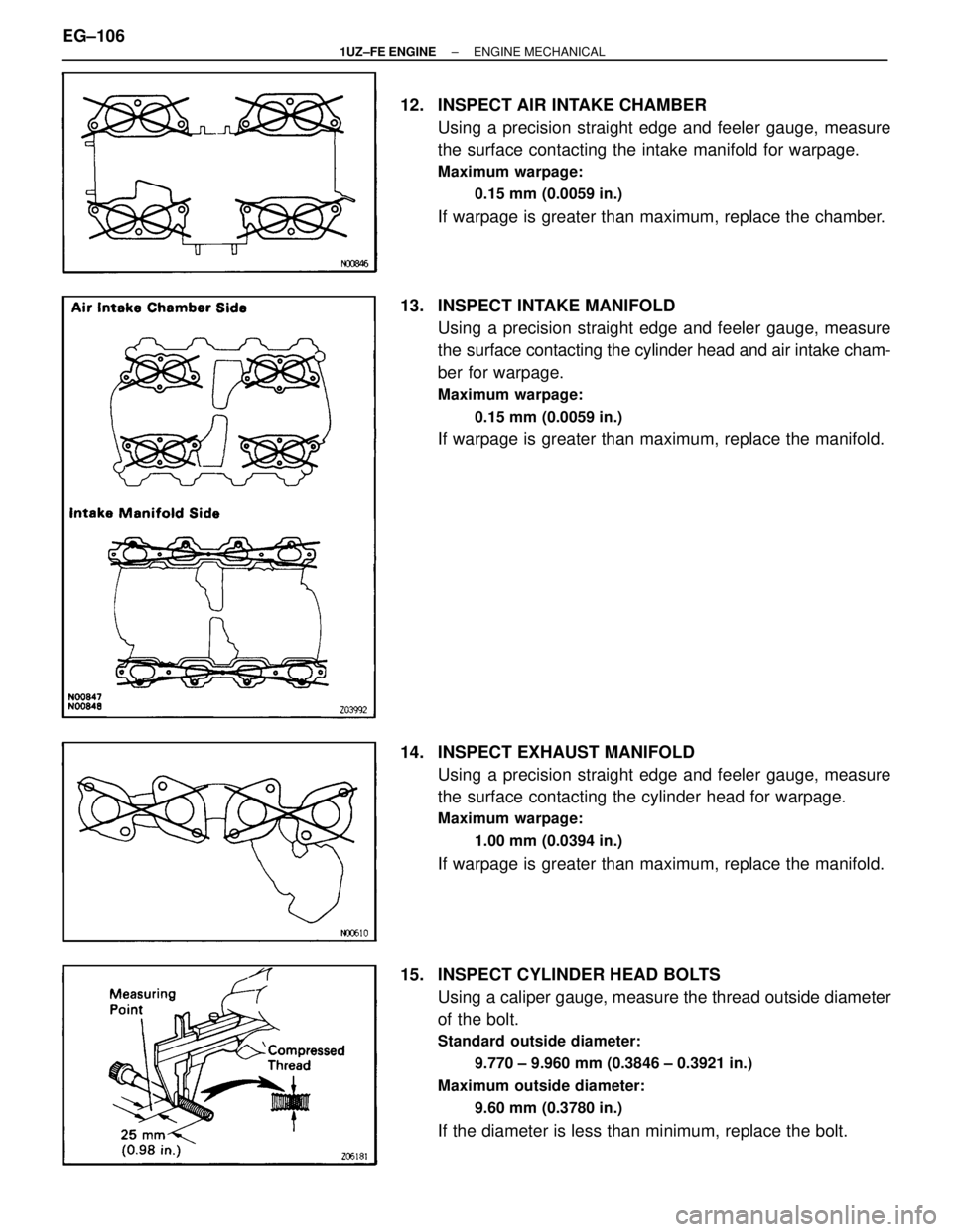
12. INSPECT AIR INTAKE CHAMBERUsing a precision straight edge and feeler gauge, measure
the surface contacting the intake manifold for warpage.
Maximum warpage:
0.15 mm (0.0059 in.)
If warpage is greater than maximum, replace the chamber.
13. INSPECT INTAKE MANIFOLD Using a precision straight edge and feeler gauge, measure
the surface contacting the cylinder head and air intake cham-
ber for warpage.
Maximum warpage:
0.15 mm (0.0059 in.)
If warpage is greater than maximum, replace the manifold.
14. INSPECT EXHAUST MANIFOLD Using a precision straight edge and feeler gauge, measure
the surface contacting the cylinder head for warpage.
Maximum warpage:
1.00 mm (0.0394 in.)
If warpage is greater than maximum, replace the manifold.
15. INSPECT CYLINDER HEAD BOLTS Using a caliper gauge, measure the thread outside diameter
of the bolt.
Standard outside diameter:
9.770 ± 9.960 mm (0.3846 ± 0.3921 in.)
Maximum outside diameter: 9.60 mm (0.3780 in.)
If the diameter is less than minimum, replace the bolt.
EG±106
±
1UZ±FE ENGINE ENGINE MECHANICAL
WhereEverybodyKnowsYourName
Page 1485 of 4087
CYLINDER HEADS INSTALLATION
EG22V±02
(See Components for Removal and Installation)
1. INSTALL RH EXHAUST MANIFOLD TO RH CYLINDERHEAD
(a) Place a new gasket on the cylinder head with the white painted marks facing the manifold side.
NOTICE: Be careful of the Installation direction.
(b) Install the ex haust manifold with 8 new nuts. Uniformly
tighten the nuts in several passes.
Torque: 44 N Vm (450 kgf Vcm, 33 ft Vlbf)
(c) Install the main heated oxygen sensor.
Torque: 44 N Vm (450 kgf Vcm, 33 ft Vlbf)
(d) Install the heat insulator with the 3 bolts.
2. INSTALL LH EXHAUST MANIFOLD TO LH CYLINDER
HEAD
(a) Place a new gasket on the cylinder head with the white
painted marks facing the manifold side.
NOTICE: Be careful of the installation direction.
±
1UZ±FE ENGINE ENGINE MECHANICALEG±109
WhereEverybodyKnowsYourName
Page 1486 of 4087
(b) Install the exhaust manifold with 8 new nuts. Uniformlytighten the nuts in several passes.
Torque: 44 N Vm (450 kgf Vcm, 33 ft Vlbf)
(c) Install the main heated oxygen sensor.
Torque: 44 N Vm (450 kgf Vcm, 33 ft Vlbf)
(d) Install the heat insulator with the 3 bolts.
3. INSTALL CYLINDER HEADS
A. Place cylinder head on cylinder block
(a) Place 2 new cylinder head gaskets in position on the cylinder
block.
HINT: On the rear side of the cylinder head gasket are
painted marks to distinguish the LH and RH banks, a white
painted mark for the RH bank and a yellow painted mark for
the LH bank.
NOTICE: Be careful of the installation direction.
(b) Place the 2 cylinder heads in position on the cylinder headgaskets.
EG±110
±
1UZ±FE ENGINE ENGINE MECHANICAL
WhereEverybodyKnowsYourName
Page 1489 of 4087
(d) RH Cylinder Head:Install the bearing cap (mark ª11º) in position with the arrow
mark facing rearward.
(e) LH Cylinder Head: Install the bearing cap (mark ª16º) in position with the arrow
mark facing forward.
(f) Install a new seal washer to the bearing cap bolt.
(g) Apply a light coat of engine oil on the threads of the bearing
cap bolt.
(h) Install the 4 bearing cap bolts. Alternately tighten bearing cap bolts.
Torque: 16 N Vm (160 kgf Vcm, 12 ft Vlbf)
HINT: Use silver colored bolts 38 mm (1.50 in.) in length.
6. ASSEMBLE EXHAUST CAMSHAFT
(a) Install the following parts: (1) Camshaft gear spring
(2) Camshaft sub±gear
(3) Wave washer
HINT: Align the pins on the gears with the spring ends.
(b) Using snap ring pliers, install the snap ring.
(c) Mount the hexagon wrench head portion of the camshaft in a vise.
NOTICE: Be careful not to damage the camshaft.
±
1UZ±FE ENGINE ENGINE MECHANICALEG±113
WhereEverybodyKnowsYourName