Page 2506 of 4087

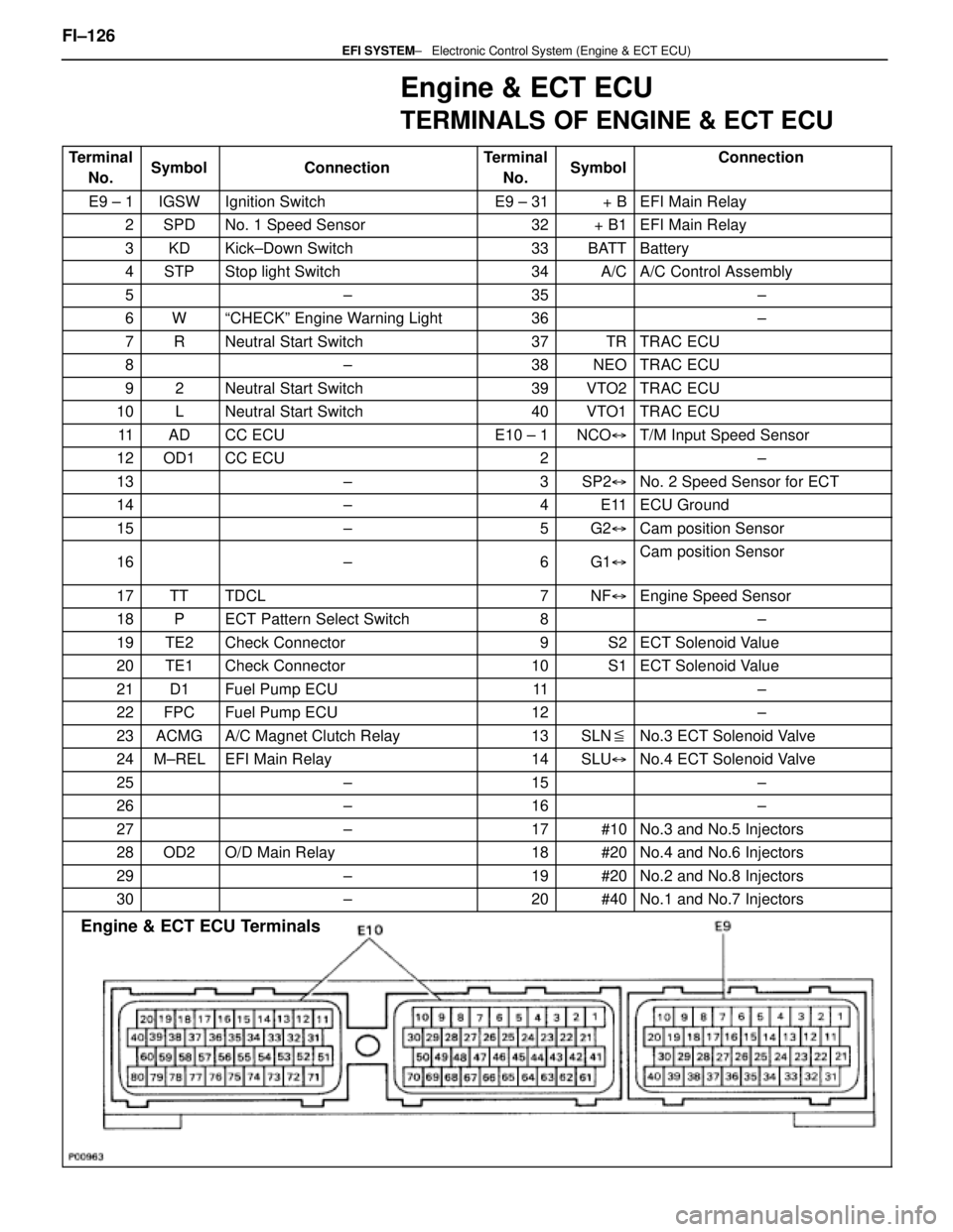
Engine & ECT ECU
TERMINALS OF ENGINE & ECT ECU
TerminalNo.SymbolConnectionTerminalNo.SymbolConnection
E9 ± 1IGSWIgnition SwitchE9 ± 31+ BEFI Main Relay
2SPDNo. 1 Speed Sensor32+ B1EFI Main Relay
3KDKick±Down Switch33BATTBattery
4STPStop light Switch34A/CA/C Control Assembly
5±35±
6WªCHECKº Engine Warning Light36±
7RNeutral Start Switch37TRTRAC ECU
8±38NEOTRAC ECU
92Neutral Start Switch39VTO2TRAC ECU
10LNeutral Start Switch40VTO1TRAC ECU
11ADCC ECUE10 ± 1NCO �T/M Input Speed Sensor
12OD1CC ECU2±
13±3SP2�No. 2 Speed Sensor for ECT
14±4E11ECU Ground
15±5G2�Cam position Sensor
16±6G1�Cam position Sensor
17TTTDCL7NF�Engine Speed Sensor
18PECT Pattern Select Switch8±
19TE2Check Connector9S2ECT Solenoid Value
20TE1Check Connector10S1ECT Solenoid Value
21D1Fuel Pump ECU11±
22FPCFuel Pump ECU12±
23ACMGA/C Magnet Clutch Relay13SLN �No.3 ECT Solenoid Valve
24M±RELEFI Main Relay14SLU�No.4 ECT Solenoid Valve
25±15±
26±16±
27±17#10No.3 and No.5 Injectors
28OD2O/D Main Relay18#20No.4 and No.6 Injectors
29±19#20No.2 and No.8 Injectors
30±20#40No.1 and No.7 Injectors
Engine & ECT ECU Terminals
FI±126 ± Electronic Control \
System (Engine & ECT ECU)EFI SYSTEM
WhereEverybodyKnowsYourName
Page 2507 of 4087

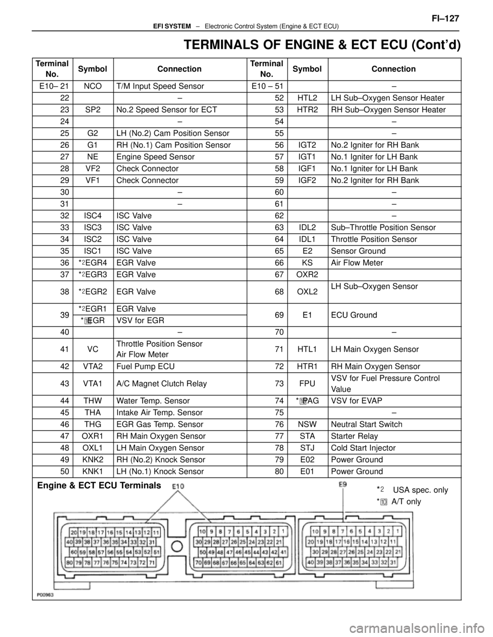
TERMINALS OF ENGINE & ECT ECU (Cont'd)
TerminalNo.SymbolConnectionTerminalNo.SymbolConnection
E10± 21NCOT/M Input Speed SensorE10 ± 51±
22±52HTL2LH Sub±Oxygen Sensor Heater
23SP2No.2 Speed Sensor for ECT53HTR2RH Sub±Oxygen Sensor Heater
24±54±
25G2LH (No.2) Cam Position Sensor55±
26G1RH (No.1) Cam Position Sensor56IGT2No.2 Igniter for RH Bank
27NEEngine Speed Sensor57IGT1No.1 Igniter for LH Bank
28VF2Check Connector58IGF1No.1 Igniter for LH Bank
29VF1Check Connector59IGF2No.2 Igniter for RH Bank
30±60±
31±61±
32ISC4ISC Valve62±
33ISC3ISC Valve63IDL2Sub±Throttle Position Sensor
34ISC2ISC Valve64IDL1Throttle Position Sensor
35ISC1ISC Valve65E2Sensor Ground
36*� EGR4EGR Valve66KSAir Flow Meter
37*� EGR3EGR Valve67OXR2
38*� EGR2EGR Valve68OXL2LH Sub±Oxygen Sensor
39*� EGR1EGR Valve69E1ECU Ground39*� EGRVSV for EGR69E1ECU Ground
40±70±
41VCThrottle Position Sensor
Air Flow Meter71HTL1LH Main Oxygen Sensor
42VTA2Fuel Pump ECU72HTR1RH Main Oxygen Sensor
43VTA1A/C Magnet Clutch Relay73FPUVSV for Fuel Pressure Control
Value
44THWWater Temp. Sensor74*� PA GVSV for EVAP
45THAIntake Air Temp. Sensor75±
46THGEGR Gas Temp. Sensor76NSWNeutral Start Switch
47OXR1RH Main Oxygen Sensor77STAStarter Relay
48OXL1LH Main Oxygen Sensor78STJCold Start Injector
49KNK2RH (No.2) Knock Sensor79E02Power Ground
50KNK1LH (No.1) Knock Sensor80E01Power Ground
Engine & ECT ECU Terminals
*��USA spec. only
* �� A/T only
FI±127EFI SYSTEM ± Electronic Control System (Engine & ECT ECU)
WhereEverybodyKnowsYourName
Page 2591 of 4087
2. REMOVE STARTER HOUSING, CLUTCH ASSEMBLYAND GEARS
(a) Remove the two mounting screws.
(b) Remove the following parts from the magnetic switch:(1) Starter housing
(2) Return spring
(3) Pinion gear
(4) Bearing
(5) Idler gear
(6) Clutch assembly
3. REMOVE STEEL BALL Using a magnetic finger, remove the steel ball from the clutch
shaft hole.
4. REMOVE BRUSH HOLDER Using a screwdriver, hold the spring back and disconnect the
brush from the brush holder. Disconnect the four brushes,
and remove the brush holder.
5. REMOVE ARMATURE FROM FIELD FRAME
ST±16
±
STARTING SYSTEM Starter
WhereEverybodyKnowsYourName
Page 2594 of 4087

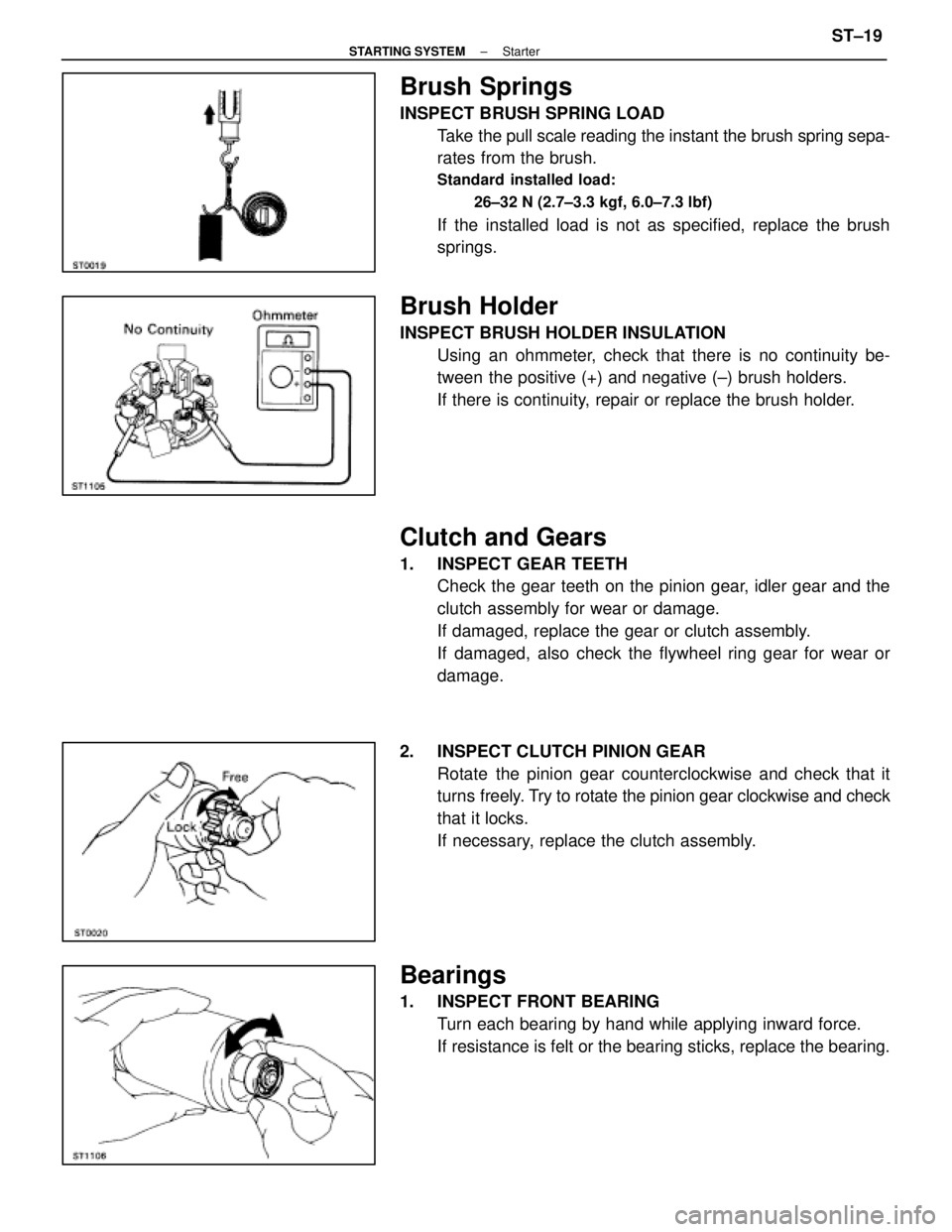
Brush Springs
INSPECT BRUSH SPRING LOADTake the pull scale reading the instant the brush spring sepa-
rates from the brush.
Standard installed load:
26±32 N (2.7±3.3 kgf, 6.0±7.3 lbf)
If the installed load is not as specified, replace the brush
springs.
Brush Holder
INSPECT BRUSH HOLDER INSULATIONUsing an ohmmeter, check that there is no continuity be-
tween the positive (+) and negative (±) brush holders.
If there is continuity, repair or replace the brush holder.
Clutch and Gears
1. INSPECT GEAR TEETHCheck the gear teeth on the pinion gear, idler gear and the
clutch assembly for wear or damage.
If damaged, replace the gear or clutch assembly.
If damaged, also check the flywheel ring gear for wear or
damage.
2. INSPECT CLUTCH PINION GEAR Rotate the pinion gear counterclockwise and check that it
turns freely. Try to rotate the pinion gear clockwise and check
that it locks.
If necessary, replace the clutch assembly.
Bearings
1. INSPECT FRONT BEARING Turn each bearing by hand while applying inward force.
If resistance is felt or the bearing sticks, replace the bearing.
±
STARTING SYSTEM StarterST±19
WhereEverybodyKnowsYourName
Page 2597 of 4087
ASSEMBLY OF STARTER
(See Components on page ST±15)
HINT: Use high±temperature grease to lubricate the bearings
and gears when assembling the starter.
1. PLACE ARMATURE INTO FIELD FRAME Apply grease to the armature bearings, and insert the arma-
ture into the field frame.
2. INSTALL BRUSH HOLDER (a) Align the claw of the brush holder with the claw grooveof the field frame.
(b) Place the brush holder on the field frame.
(c) Using a screwdriver, hold the brush spring back, and connect the brush into the brush holder. Connect the
four brushes.
NOTICE: Check that the positive (+) lead wires are not
grounded.
3. INSERT STEEL BALL INTO CLUTCH SHAFT HOLE (a) Apply grease to the steel ball.
(b) Insert the steel ball into the clutch shaft hole.
4. INSTALL CLUTCH ASSEMBLY, GEARS AND STARTER HOUSING
(a) Apply grease to the return spring.
(b) Insert the return spring into the magnetic switch hole.
ST±22
±
STARTING SYSTEM Starter
WhereEverybodyKnowsYourName
Page 2598 of 4087
(c) Place the following parts in position on the starterhousing:
(1) Clutch assembly
(2) Idler gear
(3) Bearing
(4) Pinion gear
(d) Install the starter housing to magnetic switch with the two screws.
5. INSTALL FIELD FRAME AND ARMATURE ASSEMBLY (a) Install a new O±ring to groove of the field frame.
(b) Align the claws of the brush holder with the grooves ofthe magnetic switch, and install the field frame and
armature shaft assembly.
(c) Align the punch mark of the field frame with the line of the magnet switch.
(d) Install a new O±ring to through bolt A.
(e) Install the spring washer, plate washer, wire bracket and
a new O±ring to through bolt B.
(f) Install the two through bolts.
±
STARTING SYSTEM StarterST±23
WhereEverybodyKnowsYourName
Page 2672 of 4087
Diag. Code 16ECT Control Signal Malfunction
CIRCUIT DESCRIPTION
The signal from the ECT CPU retards the ignition timeing of the engine duri\
ng ECT gear shifting, thus mo-
mentarily reducing torque output of the engine for smooth clutch operati\
on inside the transmission and re-
duced shift shock.
Code No.Diagnostic Code Detecting ConditionTrouble Area
16Fault in communications between the engine
CPU and ECT CPU in the ECU.�ECU
If the ECU records the diagnostic code ª16º in memory, it prohibits the torque control of the ECT which per-
forms smooth gear shifting.
DIAGNOSTIC CHARTDIAGNOSTIC CHART
Are there any other codes (besides Code 16)
being output?
Replace engine & ECT ECU. Go to relevant diag. code chart.
±
ENGINE TROUBLESHOOTING Circuit InspectionTR±61
WhereEverybodyKnowsYourName
Page 2906 of 4087
2. REMOVE STARTER HOUSING, CLUTCH ASSEMBLYAND GEARS
(a) Remove the two mounting screws.
(b) Remove the following parts from the magnetic switch:(1) Starter housing
(2) Return spring
(3) Pinion gear
(4) Bearing
(5) Idler gear
(6) Clutch assembly
3. REMOVE STEEL BALL Using a magnetic finger, remove the steel ball from the clutch
shaft hole.
4. REMOVE BRUSH HOLDER Using a screwdriver, hold the spring back and disconnect the
brush from the brush holder. Disconnect the four brushes,
and remove the brush holder.
5. REMOVE ARMATURE FROM FIELD FRAME
ST±16
±
STARTING SYSTEM Starter
WhereEverybodyKnowsYourName